JETWAY NF91 User manual

i
USER'S MANUAL
FOR
NF91 MOTHERBOARD
NO. G03-NF91-F
Rev
:
1.0
Release date: Aug, 2008
Trademark:
* Specifications and Information contained in this documentation are furnished for information use only, and are
subject to change at any time without notice, and should not be construed as a commitment by manufacturer.

ii
Environmental Protection Announcement
Do not dispose this electronic device into the trash while discarding. To minimize pollution
and ensure environment protection of mother earth, please recycle.

iii
USER’S NOTICE.................................................................................................................................. iv
MANUAL REVISION INFORMATION............................................................................................ iv
ITEM CHECKLIST............................................................................................................................ .iv
CHAPTER 1 INTRODUCTION
1-1 FEATURE OF MOTHERBOARD ...................................................................................... 1
1-2 SPECIFICATION.................................................................................................................. 2
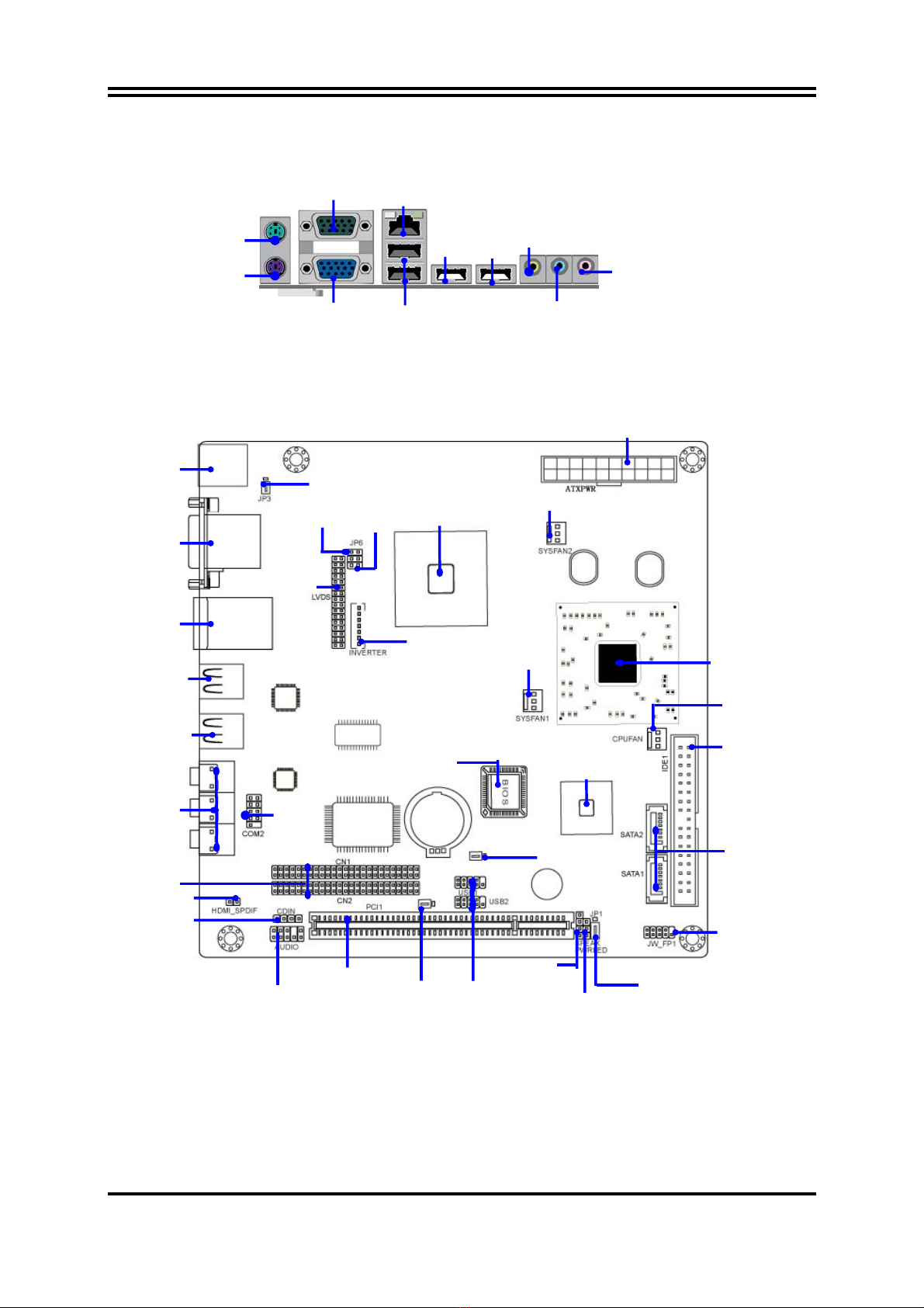
1-3 LAYOUT DIAGRAM ........................................................................................................... 3
CHAPTER 2 HARDWARE INSTALLATION
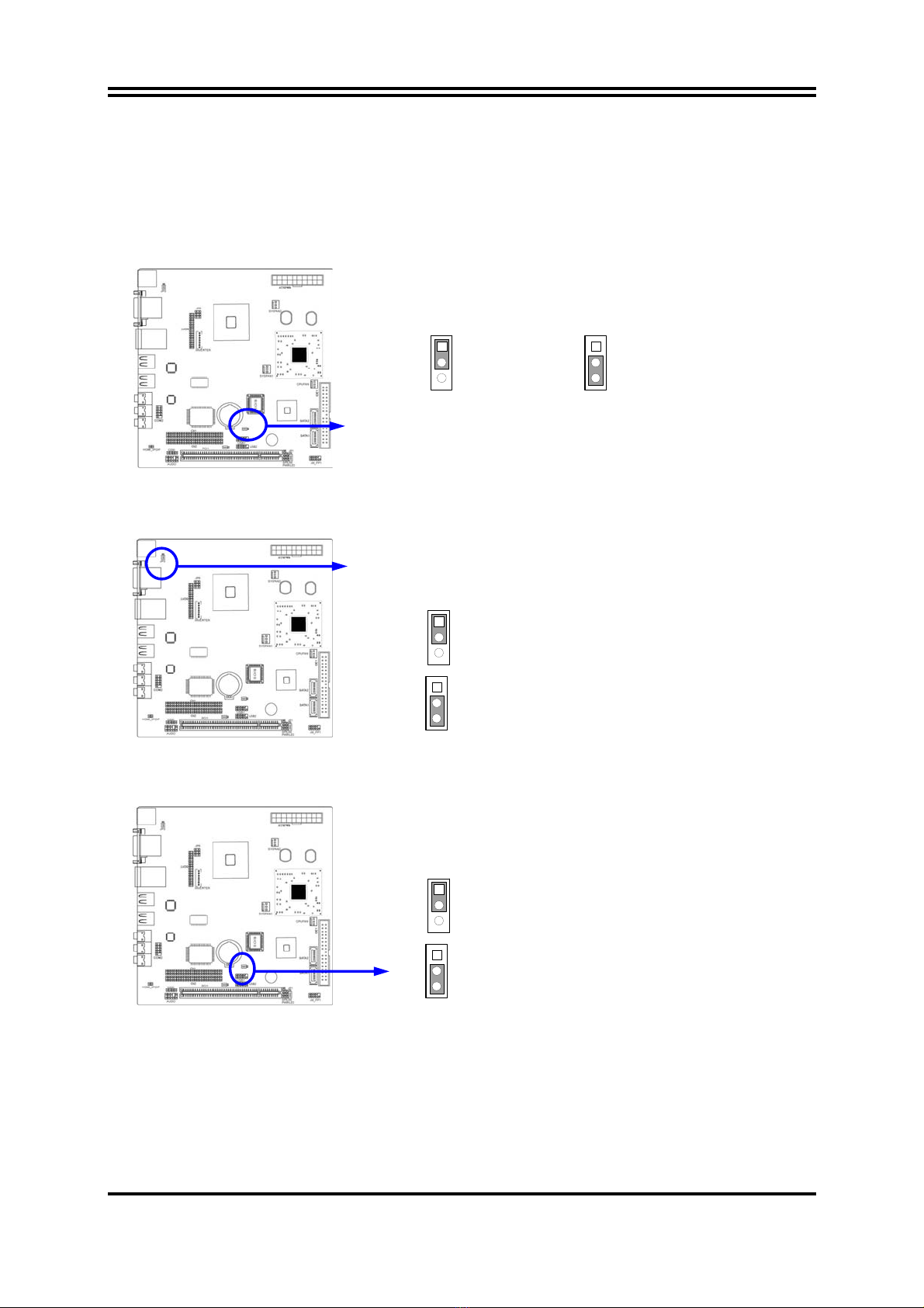
2-1 CHECKING MOTHERBOARD'S JUMPER SETTING.................................................. 6
2-2 CONNECTORS..................................................................................................................... 7
2-3 HEADERS.............................................................................................................................. 9
CHAPTER 3 INTRODUCING BIOS
3-1 ENTERING SETUP.............................................................................................................. 13
3-2 GETTING HELP................................................................................................................... 13
3-3 THE MAIN MENU................................................................................................................ 13
3-4 STANDARD CMOS FEATURES........................................................................................ 15
3-5 ADVANCED BIOS FEATURES.......................................................................................... 16
3-6 ADVANCED CHIPSET FEATURES.................................................................................. 18
3-7 INTEGRATED PERIPHERALS......................................................................................... 19
3-7-1 ONBOARD IDE FUNCTION................................................................................ 19
3-7-2 ONBOARD DEVICE FUNCTION........................................................................ 20
3-7-3 ONBOARD SUPER IO FUNCTION..................................................................... 20
3-8 POWER MANAGEMENT SETUP ..................................................................................... 21
3-9 PNP/PCI CONFIGURATION SETUP................................................................................ 22
3-10 PC HEALTH STATUS........................................................................................................ 22
3-10-1 SMART FAN CONFIGURATIONS.................................................................. 23
3-11 MISCELLANEOUS CONTROL........................................................................................ 23
3-12 LOAD STANDARD/OPTIMIZED DEFAULTS............................................................... 24
3-13 SET SUPERVISOR/USER PASSWORD........................................................................... 24
TABLE OF CONTENT

iv
USER’S NOTICE
COPYRIGHT OF THIS MANUAL BELONGS TO THE MANUFACTURER. NO PART OF THIS MANUAL,
INCLUDING THE PRODUCTS AND SOFTWARE DESCRIBED IN IT MAY BE REPRODUCED,
TRANSMITTED OR TRANSLATED INTO ANY LANGUAGE IN ANY FORM OR BY ANY MEANS WITHOUT
WRITTEN PERMISSION OF THE MANUFACTURER.
THIS MANUAL CONTAINS ALL INFORMATION REQUIRED TO USE INTEL 910 GMLE CHIPSET
MOTHER-BOARD SERIES AND WE DO ASSURE THIS MANUAL MEETS USER’S REQUIREMENT BUT WILL
CHANGE, CORRECT ANY TIME WITHOUT NOTICE. MANUFACTURER PROVIDES THIS MANUAL “AS IS”
WITHOUT WARRANTY OF ANY KIND, AND WILL NOT BE LIABLE FOR ANY INDIRECT, SPECIAL,
INCIDENTIALORCONSEQUENTIAL DAMAGES (INCLUDING DAMANGES FOR LOSS OF PROFIT, LOSS OF
BUSINESS, LOSS OF USE OF DATA, INTERRUPTION OF BUSINESS AND THE LIKE).
PRODUCTS AND CORPORATE NAMES APPEARING IN THIS MANUAL MAY OR MAY NOT BE
REGISTERED TRADEMARKS OR COPYRIGHTS OF THEIR RESPECTIVE COMPANIES, AND THEY ARE
USED ONLY FOR IDENTIFICATION OR EXPLANATION AND TO THE OWNER’S BENEFIT, WITHOUT
INTENT TO INFRINGE.
Manual Revision Information
Reversion Revision History Date
1.0 First Edition Aug. 2008
Item Checklist
5Mini-ITX IPC Board
5Mini-ITX IPC Board User’s Manual
5CD for motherboard utilities
5I/O Back Panel Shield
5Cables for IDE and Serial ATA1 IDE Port

1
Chapter 1
Introduction
1-1 Feature of motherboard
The Intel 910 GMLE chipset motherboard series are based on Intel 910 GMLE Express
Chipset and Intel FW82801FBM ICH Chipset technology which supports optional Intel ULV
Celeron M600MHz and ULV Celeron M 1GHz. The motherboard is optimized to deliver
innovative features and professional desktop platform solution with the advantages of the
new-generation dual core processor for those who demand the best experience of personal
computing.
The Intel 910 GMLE Express chipset motherboard series for optional Intel ULV Celeron
M600MHz and ULV Celeron M 1GHz Processors are absolutely the cost-effective solution for
industrial computing applications, and it also meets the demanding usage of computing of
multimedia entertainment and business applications. Moreover, the Intel 910 GMLE express
chipset incorporates Intel Graphics Media Accelerator 900 which supports the Microsoft*
DirectX* 9, Vertex Shader 2.0 and Transform and Lighting provides incredible visual quality,
faster graphics performance and flexible display options without the need for a separate
graphics card.
The motherboards implement Intel 910 GMLE Express Chipset which supports Front Side
Bus 400 MHz data transfer rate and one DDRII SO-DIMM 400 MHz DIMM which is
expandable to 1.0GB. The motherboard is embedded with ICH6M chipset of providing one
parallel Ultra ATA 100 interface for two IDE drives and two serial ATA1 interfaces of 1.5 Gb
/ s data transfer rate for two serial ATA devices.
The motherboards offer one 32-bit PCI to guarantee the rich connectivity for the I/O of
peripherals. The motherboards are designed of tackling the future requirements of industrial
computing.
The motherboards provide 10 / 100 / 1000 Ethernet compatible LAN function by using the
RTL8111C Gigabit LAN NIC which supports 10M / 100M / 1000M data transfer rate. The
motherboard series also have an integrated 6-channel High Definition Audio Codec on board
which is fully compatible with Sound Blaster Pro®that gives you the best sound quality and
compatibility.
Embedded USB and capability of expanding to 8 of USB 2.0 functional ports, these
motherboards meet the future USB demands which are also equipped with hardware monitor
function on system to monitor and protect your system and maintain your non-stop business
computing.

2
1-2 Specification
Spec Description
Design ∗Mini ITX form factor 6 layers PCB size: 17.0x17.0cm
Chipset ∗Intel 910 GMLE Memory Controller Hub (MCH) Chipset
∗Intel 82801FBM I/O Controller Hub (ICH6M) Chipset
CPU Type
∗Intel ULV Celeron M600MHz for
∗Intel ULV Celeron M1GHzM Mobile Socket 479m Processors
∗Support FSB Frequency 400 MHz
Memory Socket ∗200-pin DDR II SODIMM socket x1
∗Expandable to 1GB
x
Integrated VGA ∗Integrated Graphic Media Accelerator 900
∗Up to 224 MB maximum video memory
x
Expansion Slots ∗32-bit PCI slot x 1pcs
Integrate IDE and
Serial ATA1
∗One PCI IDE controller that supports PCI Bus Mastering, ATA PIO/DMA
and the ULTRA DMA 33/66/100 functions that deliver the data transfer
rate up to 100 MB/s;
∗Two Serial ATA1 ports provide 1.5 Gb /sec data transfer rate.
LAN
∗Integrated RTL 8111C PCI-E gigabit LAN Chip.
∗Support Fast Ethernet LAN function of providing 10Mb/100Mb/1000
Mb/s data transfer rate
Audio ∗Realtek ALC662High Definition Audio Codec integrated
∗Audio driver and utility included
BIOS ∗Award 4MB FWH Flash ROM
Multi I/O ∗PS2 Keyboard/Mouse connector
∗VGA connector.x1
∗Serial port connector, serial port header x1
∗USB 2.0 connector x 4, headers x2
∗RJ45 gigabit LAN connector x1
∗LVDS header x1
∗SPDIF header x1, IR header x1
∗6-channel Audio connector (Line-in, Line-out, MIC-In/ 6CH Audio)

3
1-3 Layout Diagram
For 910 GMLE
Intel 910 GMLE
Express Chipset
Front Panel
Connector
Clear CMOS (JP2)
ATX Powe
r
Connector
CPU FAN
Intel
CPU
Speak Header.
USB2.0 Header
(USB1, USB2)
32-bit PCI Slot
COM/VGA
Connector
CD Audio In
SPDIF Heade
r
l USB 2.0 Port
ATA100
IDE Connector
LVDS Connecto
r
USB Power ON
Jumper (JP4)
MIC-IN
Line-OUT
Line-IN
VGA
Gi
g
abit LAN
USB
Front Panel Audio
COM
PS/2 Mouse Keyboard
USB
PS/2 Mouse
PS/2 Keyboard
RJ45 LAN
Over USB Port
USB 2.0 Port
LVDS Inverter.
Audio Connecto
r
Daughter Board
Expansion Connector
SFAN2
SFAN1
Intel 82801FBM
ICH Chipset
SATA
Connector
COM2
Header
PWR LED
Header
JP6 JP5
JP3
JP1
4Mbit FWH Flash ROM BIOS
USB

4
200-pin DDRII SODIMM
N
OTE!
We strongly suggest there be a gap of at lease 5mm height reserved between this IPC
board and the button of the chassis for the space needed to install a DDRII SODIMM
at the back of the board.

5
Jumper
Jumper Name Description Page
JP2 Clear CMOS Function Setting 3-pin Block P6
JP3 KB/USB Power On Function Setting 3-pin Block P7
JP4 USB1/2 Power On Function Setting 3-pin Block P7
JP5 LVDS Inverter Power On Setting 3-pin Block P7
JP6 LVDS 5V/3.3 V Select 3-pin Block P7
Connectors
Connector Name Description Page
ATXPWR1 ATX Power Connector 24-pin Block P7
Line-In/Out, MIC-In Line-Out/Line-In/MIC-In Audio Connector 1Phone Jack P8
IDE1 Primary IDE Connector 40-pin Block P8
SATA1/2 Serial ATAI Connector 7-pin Connector P8
Headers
Header Name Description Page
AUDIO Front Panel SPEAKER, MIC header 9-pin Block P9
CDIN CD Audio-In Header 4-pin Block P9
USB1/2 USB2.0 Port Headers 9-pin Block P9
COM2 Serial Port COM1 Header 9-pin Block P9
SPEAK Speaker connector 4-pin Block P10
PWR LED Power LED Headers 2-pin Block P10
JW_FP1
(PWR LED/ IDE LED/
/Power Button /Reset)
Front Panel Headers
(PWR LED/ IDE LED/ /Power Button
/Reset)
9-pin Block P10
CPUFAN, SFAN1/2 FAN Speed Headers 3-pin Block P10
SPDIF SPDIF Headers 2-pin Block P11
LVDS LVDS Connector 32-pin Block P11
Inverter LVDS Inverter Connector 7-pin Block P13
CN1/CN2 Daughter Board Expansion Headers 50-pin Block P13
Expansion Sockets
Socket/Slot Name Description Page
DDRII DDRII SDRAM Module
Socket 200-pin DDRII SO-DIMM Module
Expansion Socket N/A
PCI1 PCI Slot 32-bit PCI Local Bus Expansion slot N/A

6
Chapter 2
Jumper Setting, Connector & Header
2-1 Checking Motherboard’s Jumper Setting
(1) CMOS RAM Clear (3-pin): JP2
(2) USB Power On function Enabled/Disabled (3-pin): JP3
When setting Enabled you can use USB Device to power on system.
(3) USB Power On function Enabled/Disabled (3-pin): JP4
When setting Enabled you can use USB Device to power on system.
CMOS Clear Setting
2-3 closed Clear CMOS
JP2 JP2
1-2 closed Normal (Default)
1
3
1
3
1-2 closed KB/USB Power On Disabled (Default)
2-3 closed KB/USB Power On Enabled
JP3
JP3
1
3
1
3
1-2 closed USB Power On Disabled (Default)
2-3 closed USB Power On Enabled
JP4
JP4
1
3
1
3

7
(4) LVDS Inverter Function setting (3-pin): JP5
LVDS Inverter Function Setting
2-3 closed: Inverter Black Lighters Off
JP5 1
3
JP5 1
3
1-2 closed :Inverter Black Lighters On
(5) LVDS Function setting (3-pin): JP6
LVDS Function Setting
2-3 closed : LCD powered by 3.3V
JP6 1
3
JP6 1
3
1-2 closed: LCD Powered by 5V
2-2 Connectors
(1) Power Connector (20-pin block): ATXPWR1
(2)Audio Connector: (Line-Out/ Line-IN/ MIC-In)
This Connector is a 3-phone Jack for LINE-OUT/ LINE-IN/ MIC.
Line-out : Audio output to speaker
Line-In : Audio input to Audio controller
MIC-In : Microphone Connector
ATX Power Connector

8
(3)Primary IDE Connector (40-pin block): IDE1
Pin 1
IDE1
•Two hard disks can be connected to each connector. The first HDD is referred to as the
“Master” and the second HDD is referred to as the “Slave”.
•For performance issues, we strongly suggest you don’t install a CD-ROM or DVD-ROM
drive on the same IDE channel as a hard disk. Otherwise, the system performance on this
channel maybe low.
(4) Serial-ATA Port connector: SATA1/SATA2
Serial-ATA Connectors
SATA2 SATA1

9
2-3 Headers
(1) Line-Out, MIC-In Header (9-pin): AUDIO
This header connects to Front Panel Line-out, MIC-In connector with cable.
Line-Out, MIC Headers
A
UDIO
Pin 1
MIC2-L
LINEOUT2-L
MIC2-R
LINEOUUT2-R
SENSE-FB
AUD
_
GND
AUD
_
GND
AUD
_
GND
AUD
_
JD 9
2
9
10
(2) CD Audio-In Headers (4-pin): CDIN
CDIN are the connectors for CD-Audio Input signal. Please connect it to CD-ROM
CD-Audio output connector.
CD Audio-In Headers
CDIN 4 1
GND
CD-R CD-LGND
(3) USB Port Headers (9-pin): USB1/USB2
These headers are used for connecting the additional USB port plug. By attaching an
option USB cable, your can be provided with two additional USB plugs affixed to the
back panel.
USB Port Headers
Pin 1
USB 1/2
VCC
-DATA
GND
+DATA
VCC
NC
-DATA
GND
+DATA

10
(4) Serial Port Connector (9-pin female): COM2
COM2 is a 9-pin RS232 D-Subminiature serial port connector.
DCD
Pin1 Pin6
Serial COM Port 9-pin Block
DSR
RXD
TXD
DTR
GND
RTS
GTS
RI
(5) Speaker connector: SPEAK
This 4-pin connector connects to the case-mounted speaker. See the figure below.
(6) Power LED: PWR LED
The Power LED is light on while the system power is on. Connect the Power LED
from the system case to this pin.
(7) IDE Activity LED: HD_LED
This connector connects to the hard disk activity indicator light on the case.
(8) Reset switch lead: RESET
This 2-pin connector connects to the case-mounted reset switch for rebooting your
computer without having to turn off your power switch. This is a preferred method of
rebooting in order to prolong the lift of the system’s power supply. See the figure
below.
(9)Power switch: PWR BTN
This 2-pin connector connects to the case-mounted power switch to power ON/OFF the
system.
System Case Connections
HDLED
RESET
VCC5
GND
VCC5 PWR LED
PWRBTN
PWRBTN
PWRLED
HDDLED
RSTSW
NC GND
JW FP
Pin 1
SPEAK
SPEAK
GND
NC
VCC5
Pin 1
PWRLED
Pin 1
(10)FAN Speed Headers (3-pin): CPUFAN, SFAN1/SFAN2
These connectors support cooling fans of 350mA (4.2 Watts) or less, depending on the
fan manufacturer, the wire and plug may be different. The red wire should be positive,
while the black should be ground. Connect the fan’s plug to the board taking into
consideration the polarity of connector.

11
SFAN2
1
3
SFAN1
1
3
CPUFAN
1
3
(11) SPDIF Out header: SPDIF
(12) LVDS Pin-Headers: LVDS
These Headers can connect with the
LVDS devices.
Pin 1
LVDS Header
Pin 2
PIN No. Symbol PIN NO. Symbol
1 NC 2 NC
3 CK2IN- 4 CK2IN+
5 R2IN2- 6 R2IN2+
7 R2IN1- 8 R2IN1+
9 R2IN0- 10 R2IN0+
11 LVDS_DDC_DATA 12 LVDS_DDC-CLK
13 GND 14 GND
15 GND 16 GND
17 NC 18 NC
19 CK1IN+ 20 CK1IN-
21 R1IN2+ 22 R1IN2-
23 R1IN1+ 24 R1IN1-
25 R1IN0+ 26 R1IN0-
27 VDD 28 VDD
29 VDD 30 VDD
31 GND 32 GND
12
SPDIF
_
OUT
GND
SPDIF_OUT

12
(13) Pin-headers of LVDS Inverter: Inverter
Pin 1
LVDS Inverter
Pin 2
VIN
VIN
GND
GND
Panel Backlight Enable
Panel Backlight Control
GND
(14) Expansion Daughter Board Headers: CN1/CN2
Chapter 3
Introducing BIOS
The BIOS is a program located on a Flash Memory on the motherboard. This program is a
bridge between motherboard and operating system. When you start the computer, the BIOS
program will gain control. The BIOS first operates an auto-diagnostic test called POST
(power on self test) for all the necessary hardware, it detects the entire hardware device and
configures the parameters of the hardware synchronization. Only when these tasks are
completed done it gives up control of the computer to operating system (OS). Since the
BIOS is the only channel for hardware and software to communicate, it is the key factor for
system stability, and in ensuring that your system performance as its best.
In the BIOS Setup main menu of Figure 3-1, you can see several options. We will explain
these options step by step in the following pages of this chapter, but let us first see a short
description of the function keys you may use here:
•Press <Esc> to quit the BIOS Setup.
•Press ↑↓←→ (up, down, left, right) to choose, in the main menu, the option you want to
confirm or to modify.
•Press <F10> when you have completed the setup of BIOS parameters to save these
parameters and to exit the BIOS Setup menu.
To install a daughter board into CN1, CN2 is very easy, user just press down the daughter board directly into
these two connectors, in the direction shown as the above picture.
Press Down Directly

13
•Press Page Up/Page Down or +/– keys when you want to modify the BIOS parameters for
the active option.
3-1 Entering Setup
Power on the computer and by pressing <Del> immediately allows you to enter Setup.
If the message disappears before your respond and you still wish to enter Setup, restart the
system to try again by turning it OFF then ON or pressing the “RESET” button on the system
case. You may also restart by simultaneously pressing <Ctrl>, <Alt> and <Delete> keys.
If you do not press the keys at the correct time and the system does not boot, an error message
will be displayed and you will again be asked to
Press <F1> to continue, <Del> to enter Setup
3-2 Getting Help
Main Menu
The on-line description of the highlighted setup function is displayed at the bottom of the
screen.
Status Page Setup Menu/Option Page Setup Menu
Press F1 to pop up a small help window that describes the appropriate keys to use and the
possible selections for the highlighted item. To exit the Help Window, press <Esc>.
3-3 The Main Menu
Once you enter Award®BIOS CMOS Setup Utility, the Main Menu (Figure 3-1) will appear
on the screen. The Main Menu allows you to select from fourteen setup functions and two
exit choices. Use arrow keys to select among the items and press <Enter> to accept or enter
the sub-menu.
CMOS Setup Utility – Copyright(C) 1984-2004 Award Software
Standard CMOS Features
Advanced BIOS Features
Advanced Chipset Features
Integrated Peripherals
Power Management Setup
PnP/PCI Configurations
PC Health Status
Miscellaneous Control
Load optimized Defaults
Load Standard Defaults
Set Supervisor Password
Set User Password
Save & Exit Setup
Exit Without Saving
Esc : Quit ↑↓→← : Select Item
F10 : Save & Exit Setup
Time, Date, Hard Disk Type...
Figure 3-1
Standard CMOS Features
Use this Menu for basic system configurations.

14
Advanced BIOS Features
Use this menu to set the Advanced Features available on your system.
Advanced Chipset Features
Use this menu to change the values in the chipset registers and optimize your system’s
performance.
Integrated Peripherals
Use this menu to specify your settings for integrated peripherals.
Power Management Setup
Use this menu to specify your settings for power management.
PnP/PCI configurations
This entry appears if your system supports PnP/PCI.
PC Health Status
This entry shows your PC health status.
Miscellaneous Control
Use this menu to specify your settings for Miscellaneous Control.
Load Optimized Defaults
Use this menu to load the BIOS default values that are settings for optimal performances
system operations.
Load Standard Defaults
Use this menu to load the BIOS default values that are factory settings for the stable
performance system operation.
Set Supervisor/User Password
Use this menu to set User and Supervisor Passwords.
Save & Exit Setup
Save CMOS value changes to CMOS and exit setup.
Exit Without Saving
Abandon all CMOS value changes and exit setup.

15
3-4 Standard CMOS Features
The items in Standard CMOS Setup Menu are divided into several categories. Each
category includes no, one or more than one setup items. Use the arrow keys to highlight the
item and then use the <PgUp> or <PgDn> keys to select the value you want in each item.
Phoenix – AwardBIOS CMOS Setup Utility
Standard CMOS Features
Item Help
Date (mm:dd:yy) Tue, Jul, 15 2008
Time (hh:mm:ss) 11 : 02 : 35
> SATA Port 0 Master None
> SATA Port 1 Slave None
> IDE Channel 1 Master None
> IDE Channel 1 Slave None
Video EGA/VGA
Halt On All Errors
Base Memory 639K
Extended Memory 1039360K
Total Memory 1040384K
Menu Level >
Change the day, month,
year and century
↑↓→← Move Enter:Select +/-/PU/PD:Value F10:Save ESC:Exit F1:General Help
F5:Previous Values F6:Optimized Defaults F7:Standard Defaults
Date
The date format is <day><month><date><year>.
Day Day of the week, from Sun to Sat, determined by BIOS. Read-only.
Month The month from Jan. through Dec.
Date
The date from 1 to 31 can be keyed by numeric function keys.
Year The year depends on the year of the BIOS.
Time
The time format is <hour><minute><second>.
IDE Channel 1 Master / Channel 1 Slave
SATA Port 0 /Port 1Master / Slave
Press PgUp/<+> or PgDn/<–> to select Manual, None, Auto type. Note that the
specifications of your drive must match with the drive table. The hard disk will not work
properly if you enter improper information for this category. If the type of hard disk drives
is not matched or listed, you can use Manual to define your own drive type manually.
If you select Manual, related information is asked to be entered to the following items. Enter
the information directly from the keyboard. This information should be provided in the
documentation from your hard disk vendor or the system manufacturer.
If the controller of HDD interface is SCSI, the selection shall be “None”.
If the controller of HDD interface is CD-ROM, the selection shall be “None”
Access Mode The settings are Auto Normal, Large, and LBA.
Cylinder number of cylinders
Head number of heads
Precomp write precomp
Landing Zone landing zone
Sector number of sectors

16
3-5 Advanced BIOS Features
Phoenix – AwardBIOS CMOS Setup Utility
Advanced BIOS Features
Item Help
Virus Warning Disabled
CPU Feature Press Enter
Hard Disk Boot Priority Press Enter
Quick Power On Self Test Enabled
First Boot Device Hard Disk
Second Boot Device CDROM
Third Boot Device USB-ZIP
Boot other Device Enabled
Boot Up NumLock Status On
Typematic Rate Setting Disabled
Typematic Rate (Chars/Sec) 6
Typematic Delay (Msec) 250
Security Option Setup
APIC Mode Enabled
MPS Version Control For OS 1.4
OS Select For DRAM > 64MB Non-OS2
HDD S.M.A.R.T Capability Disabled
Report No FDD for windows Yes
Menu Level >
↑↓→← Move Enter:Select +/-/PU/PD:Value F10:Save ESC:Exit F1:General Help
F5:Previous Values F6:Optimized Defaults F7:Standard Defaults
Virus Warning
Allows you to choose the VIRUS Warning feature for IDE Hard Disk boot sector protection.
If this function is enabled and someone attempt to write data into this area, BIOS will show a
warning message on screen and alarm beep.
Disabled (default) No warning message to appear when anything attempts to access the
boot sector or hard disk partition table.
Enabled Activates automatically when the system boots up causing a warning
message to appear when anything attempts to access the boot sector
of hard disk partition table.
Hard Disk Boot Priority
The selection is for you to choose the hard disk drives priorities to boot from.
Quick Power On Self Test
This category speeds up Power On Self Test (POST) after you power on the computer. If
this is set to Enabled. BIOS will shorten or skip some check items during POST.
Enabled (default) Enable quick POST
Disabled Normal POST
First/Second/Third Boot Device
The BIOS attempts to load the operating system from the devices in the sequence selected in
these items. The settings are LS120, Hard Disk, CDROM, ZIP100, USB-FDD, USB-ZIP,
USB-CDROM, Legacy LAN, and Disabled.
Boot Other Device
The optional settings are: Disabled and Enabled.
Boot Up NumLock Status
The default value is On.
Table of contents
Other JETWAY Motherboard manuals

JETWAY
JETWAY 627FWE User manual

JETWAY
JETWAY P4845DDA User manual

JETWAY
JETWAY J7F4-F User manual

JETWAY
JETWAY 865GVBMS User manual

JETWAY
JETWAY 868ASR1A User manual

JETWAY
JETWAY NF792R Series User manual

JETWAY
JETWAY NF796M-H310 Series User manual

JETWAY
JETWAY NU591S User manual

JETWAY
JETWAY 694AS User manual

JETWAY
JETWAY V400DA1A User manual

JETWAY
JETWAY NF796 User manual

JETWAY
JETWAY NF9V User manual

JETWAY
JETWAY M26GT4SVM User manual

JETWAY
JETWAY 618AFR5A User manual

JETWAY
JETWAY 866ASR4A User manual

JETWAY
JETWAY JNP891P Series User manual

JETWAY
JETWAY S445R1A User manual

JETWAY
JETWAY MM10-H6100 User manual

JETWAY
JETWAY P4X40DAR2A User manual

JETWAY
JETWAY 618AFP2A User manual