JFE Advantech RINKO FT User manual

取A-0133-02
Fast optical DO sensor for integration
RINKO FT
(Model name: ARO-FT, AROD-FT)
User’s Manual
1. Use after thoroughly reading this manual.
2. Improper use can lead to accidents.
3. Safely keep this manual in order not to lose it.
For safe use


1
Introduction
RINKO FT (model name: ARO-FT, AROD-FT) is a small, fast-response, and high-precision sensor for
measurements of water temperature and dissolved oxygen (DO).
The communication method can be selected from UART (3.3V logic) and RS-232C according to the float
specifications.
Possible to attach/detach the main unit without changing the float inner pressure for calibration/inspection.
Span/zero calibration is possible by the calibration kit (optional).
Table of Contents
1Terminology and Part Names .......................................................................................................... 2
2Package Contents............................................................................................................................. 4
3Safety Warning .................................................................................................................................. 6
4Precautions for Usage...................................................................................................................... 8
5Method for Connection..................................................................................................................... 9
6Maintenance and Inspection.......................................................................................................... 13
7Span/zero Calibration (optional) ................................................................................................... 14
8Troubleshooting.............................................................................................................................. 29
9Specifications.................................................................................................................................. 31
10 Warranty........................................................................................................................................... 36
Appendix 1: Command reference
Appendix 2: Command summary
Appendix 3: Examples of operation sequence

2
1Terminology and Part Names
Terminology1.1
Term Description
Instrument Refers to RINKO FT (ARO-FT/AROD-FT).
Physical quantity Refers to values, such as water temperature and DO, calculated from the AD
value with calibration coefficients.
Standard type
(ARO-FT) Refers to RINKO FT with standard mounting attachment.
Cable type
(ARO-FT) Refers to RINKO FT with LEMO connector.
MCBH type
(AROD-FT) Refers to RINKO FT with Impulse MCBH connector for deep sea (6700 m).

3
Part names1.2
Standard mounting attachment
Insulation screw
Figure 1.2 Cable type (ARO-FT)
Figure 1.1 Standard type (ARO-FT)
Main Unit
Oxygen detection film
Temperature sensor
Lock-nut
Locking sleeve
LEMO connector
Figure 1.3 MCBH type (AROD-FT)
MCBH connector

4
2Package Contents
ARO-FT2.1
(1) Basic Package
No. Items QTY.
1 ARO-FT main unit
1
2 Protection cap
1
3
Standard mounting attachment
or
3m cable with LEMO connector and pigtail end
1
4 User’s Manual (this manual)
1
5 Calibration certificate
1
Note: the above list indicates the basic package. The content may differ depending on the order.
(2) Optional parts
No. Items QTY.
1 Cable with LEMO connector and USB converter 1
2 Application CD
1
3 Bubbling kit
1
4 Mini-USB cable
1

5
AROD-FT2.2
(1) Basic Package
No. Items QTY.
1 AROD-FT main unit
1
2 Protection cap
1
3 Dummy cap
1
4 User’s Manual (this manual)
1
5 Calibration certificate
1
Note: The above list indicates the basic package. The content may differ depending on the order.
(2) Optional parts
No. Items QTY.
1 Cable with MCIL and D-sub 9 pin connectors
1
2 Application CD
1
3 Bubbling kit
1

6
3Safety Warning
Danger
Indicate[s] a hazardous situation which, if not avoided, will result in
death or serious injury. The signal word "DANGER" is to be limited to
the most extreme situations.
Warning
Indicate[s] a hazardous situation which, if not avoided, could result in
death or serious injury.
Caution Indicate[s] a hazardous situation which, if not avoided, could result in
minor or moderate injury.
Indicates general precautions.
Indicates supplements to control method and convenient functions.
Danger
Ensure safety for operations on water or ships.
Warning
Do not damage the cables.
Do not modify.
Do not use it with a power supply beyond the rated values.
Do not disassemble.
It can cause fire or electrocution.
Do not directly look at the excitation light for a long time.
It can damage the eyes.
Make Sure to Read This before Use

7
Caution
Do not apply strong force or impact on the sensor.
It can lead to damage, which may cause injury and seepage of water into the instrument.
Do not hang by holding only the lead wire.
It can lead to a broken wire or damaged instrument.
Make sure to insert the connector completely up to its base.
It may cause seeping of water into the instrument.
Do not leave the instrument in a place with high temperature (e.g. under direct sunlight)
for a long time.
It can accelerate the degradation of the oxygen detection film.
When attaching, make sure to tighten the screw all the way.
Loosely attached screws can compromise the water-proof property and may cause seeping of
water into the instrument.

8
4Precautions for Usage
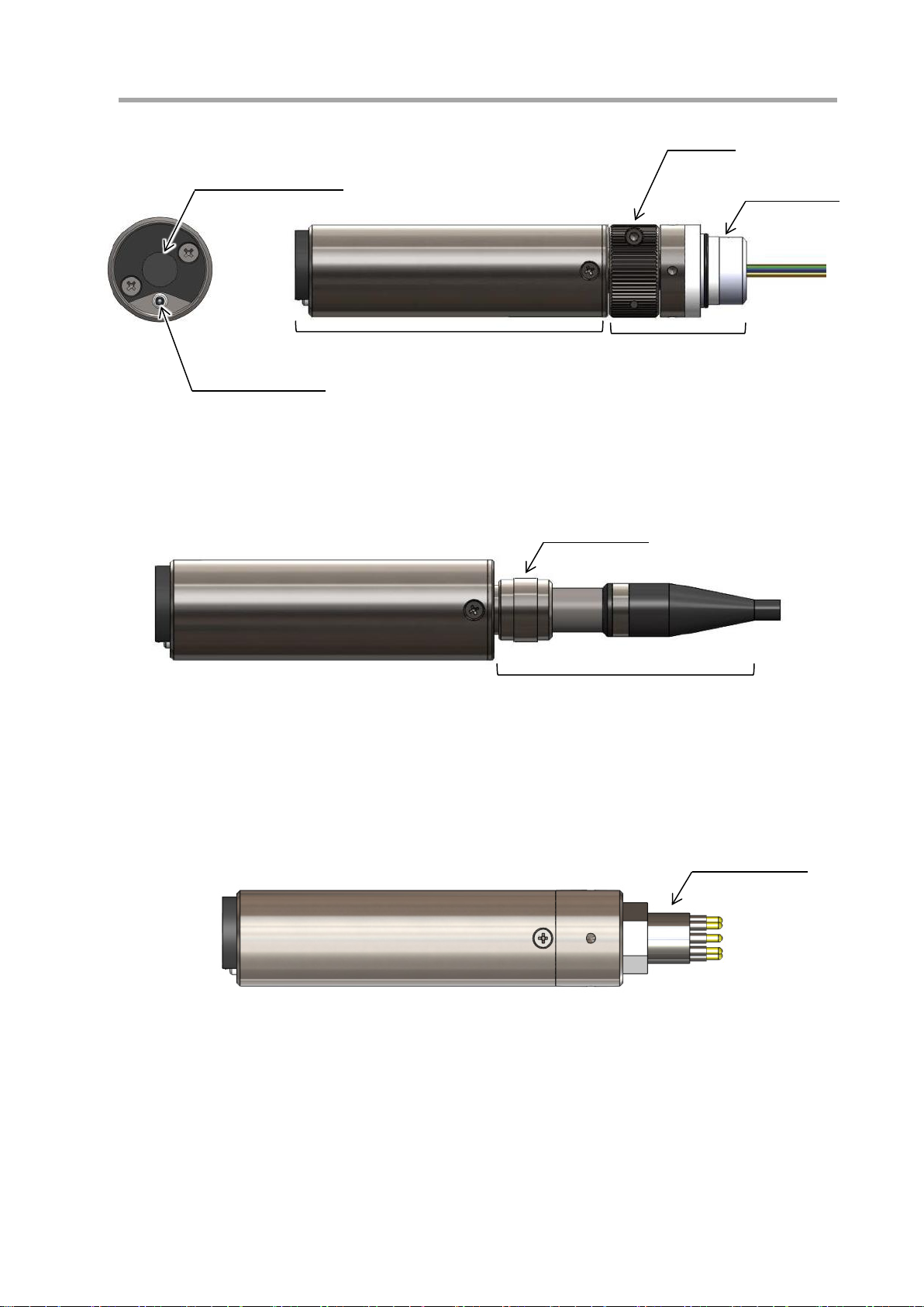
Use of instrument4.1
(1) After every use, clean with fresh water, remove moisture with a soft cloth, and store securely.
(2) The oxygen detection film is highly delicate and requires handling with care. Significant damage causes
inaccurate data and requires a replacement of the oxygen detection film.
(3) When not in use, place the protection cap and turn off the power supply.
(4) Do not drop the instrument or apply impact.
(5) Before touching the instrument, release static electricity by touching a metal.
(6) As storage location, avoid places with temperature above 40 °C, high humidity, or high amount of dust.
(7) If the instrument was not used for a long time, inspect each part before connecting to the power supply.
(8) When using the instrument in water, it is recommended to use it at 30 °C or below. When it is used in
water at 30 °C or above, the tracking for correction of temperature change can slow down, requiring
more time to resume to the normal value.
(9) The insulation screw is for preventing electrolytic corrosion due to contacts between different metals.
Software4.2
(1) It is prohibited to copy or reproduce part or whole of the software without JFE Advantech’s written
approval.
(2) The content and specifications may change without notice.
(3) We try our utmost to comprehensive content, but please contact JFE Advantech for any suspicion or
suggestions.
(4) In this user’s manual, Microsoft Windows 7/8/8.1 is used for demonstrations. Computer’s control
display or method may be different depending on the environment used.
Disposal4.3
When disposing of this product, ensure to abide by law and regulations.

9
5Method for Connection
Wiring5.1
5.1.1 Standard type (ARO-FT)
The wire color varies depending on the communication method, UART (3.3V logic) or RS-232C. Make
the connection after checking the communication method.
(RX and TX are from the instrument side.)
Color UART (3.3 V logic) RS-232C
Red Power input (6 - 26 VDC)
Black GND
Green FG
Yellow N.C. (2) RX
White N.C. (
2
) TX
Blue RX (
1
) N.C. (
2
)
Grey TX N.C. (
2
)
5.1.2 Cable type (ARO-FT)
The Cable type is only for RS-232C communication.
(RX and TX are from the instrument side.)
Green RS-232C
Red Power input (6 - 26 VDC)
Black GND
Green FG
Yellow RX
White TX
5.1.3 MCBH type (AROD-FT)
The MCBH type is only for RS-232C communication.
(RX and TX are from the instrument side.)
Pin No. RS-232C
1 N.C. (1)
2 RX
3 TX
4 N.C. (
1
)
5 FG
6 N.C. (
1
)
7 GND
8 Power input (6 - 26 VDC)
Note (1): Do not connect wires to N.C. ports. It can damage the instrument.
Note (1): 100 kΩ pull-down
Note (2): Do not connect wires to N.C. ports.
It can damage the instrument.

10
Attaching and detaching the attachment/connectors5.2
5.2.1 Standard type (ARO-FT)
(1) How to attach
Make sure that the O-rings are free of dust.
Insert slowly so as not to warp or pinch the O-rings.
Before use, check if the connector is inserted to the point you cannot turn it any more.
Incomplete insertion can cause damage to the instrument due to the seepage of water.
(2) How to detach
Pulling out the hex bolts disassembles the lock-nuts, then you will be able to detach.
Before attaching again, apply adequate amount of grease on the O-rings.
When detaching, hold the metal part and pull it out. Pulling only the cable can break it.
Insert the connector into the main unit until two black
O-rings are completely hidden. Hold it in while going to
the next step.
Attach a half of the two lock-nuts,
while pushing the connector and the main unit towards to each
other. When you do so, make sure that the red O-ring is squashed (almost invisible) by the connector
and the main unit.
Red O-ring is completely exposed.
Gap: approx. 0.5 mm
While holding them together, place two lock-nuts and
temporary fix the position by using two hex-bolts
(M3×10) just enough to combine two lock-nuts into
one. Screw the Lock-nut tightly onto the main unit to
the point you cannot turn it any more. Then, tighten the
two hex bolts completely.
OK NG

11
5.2.2 Cable type (ARO-FT)
(1) How to attach
Make sure that the O-rings are free of dust.
Insert slowly so as not to warp or pinch the O-rings.
Before use, check if the connector is inserted up to its base. Incomplete insertion can
cause damage to the instrument due to the seepage of water.
(2) How to detach
It can be pulled out by loosening the locking sleeve.
Before attaching again, apply adequate amount of grease on the O-rings.
When detaching, hold the metal part and pull it out. Pulling only the cable can break it.
Insert the connector into the main unit until two black
O-rings are completely hidden. Hold it in while going to
the next step.
Tighten the locking sleeve up to its base while pushing the
connector against the main unit (see below).
Check if the screw thread is completely hidden.
Thread is completely hidden. Thread is visible.
OK NG

12
5.2.3 MCBH type (AROD-FT)
(1) How to attach
Before use, check if the connector is inserted up to its base. Incomplete insertion can
cause damage to the equipment.
(2) How to detach
It can be pulled out by loosening the locking sleeve.
Before attaching again, apply adequate amount of grease on the O-rings.
When detaching, hold the connector and pull it out. Pulling only the cable can break it.
Insert the connector into the main unit until
there is no gap between.
Tighten the locking sleeve up to its base while
pushing the connector into the main unit.

13
6Maintenance and Inspection
Before use6.1
(1) Check that the sensor surface is free of any foreign object.
(2) Check that there is no loose or damaged connector or screw.
(3) Span/zero calibration is recommended before use.
(4) Make sure to remove the protection cap before use.
Maintenance after use6.2
(1) After use, clean well with fresh water. If something cannot be removed by water, gently remove it with a
soft cloth. Rubbing it hard can damage the oxygen detection film.
(2) After water cleaning, remove the moisture either by an air blower or by wiping with a soft cloth.
(3) Check if there is no scratch or damage on the sensor.
Storage6.3
(1) For storing, avoid places with high temperature, high humidity, or direct sunlight.
(2) Place the sensor protection cap when storing in order to protect the sensor and prevent degradation.
(3) Avoid places with temperature higher than 40 °C as it can cause output error or degradation of the
oxygen detection film.

14
7Span/zero Calibration (optional)
Span/zero calibration is available using the calibration kit (option).
Installation of software7.1
Install the RINKO FT calibration software, FT-Calib, on your PC.
(1) Insert the attached CD into the CD-ROM drive of the computer.
(2) Installation starts automatically, go to (5). If it does not start, go to (3).
(3) Open [Computer] from the start menu, and select the drive with the CD-ROM.
(4) Double-click “setup.exe”.
(5) Screens are displayed in the following order. Follow the guidance to install the software.
After the installation is completed, the “FT-Calib” icon appears on the desktop and in the start menu [All
Programs > JFE Advantech > FT-Calib].
(1) Preparing to install (2) [Next >]
(3) Start installation by clicking [Install]. (4) Installing

15
If the OS is Windows Vista or later, User Account Control (UAC) dialog may be
displayed during installation for security.
If UAC dialog appears, select [Yes] to continue the installation.
UAC dialog might not appear depending on the computer setup, but this is not
abnormal.
(5) Complete the installation by clicking [Finish].
“FT-Calib” icon

16
Installation of driver7.2
(1) The screen below will be displayed if the interface is connected to the computer.
(2) The driver needs to be installed if it displays the screen below. Follow the steps below.
Following procedures are not necessary if the driver is properly installed.
(3) Open [Control Panel] from start menu and click [Hardware and Sound].
(4) Click [Device Manager].

17
(5) If the driver cannot be installed, there will be an item with [!] mark as shown below.
(6) Right-click the item with the [!] mark and click [Update Driver Software…]
(7) Click [Browse my computer for driver software].
(8) Click [Browse…] button and select the CD-ROM or the [ARO-FT Driver] folder inside where
“FT-Calib” folder was installed. After selecting, click the [Next] button.

18
(9) If it displays the screen below, click [Install this driver software anyway].
(10) If it displays the screen below, you have succeeded with the driver installation.
Check the Device Manager to make sure that the marks such as [!] and [?] have disappeared. If the
marks are still present, try the same procedure again.
This manual suits for next models
2
Table of contents
Popular Accessories manuals by other brands

Balluff
Balluff IO-Link BLA D Series user guide

WTFF GROUP
WTFF GROUP G1-2000 operating instructions

S+S Regeltechnik
S+S Regeltechnik HYGRASGARD KFF Operating Instructions, Mounting & Installation

Nexen
Nexen PH30P user manual

Innergie
Innergie PocketCell user manual

Serene House
Serene House Cube instruction manual