manuals.online logo
Brands
  1. Home
  2. •
  3. Brands
  4. •
  5. Optex
  6. •
  7. Accessories
  8. •
  9. Optex ProSafe OA-Presence User manual

Optex ProSafe OA-Presence User manual

MANUFACTURER’ S STATEMENT
OA-Presence
Read this Operation Manual carefully before use, to ensure proper operation of this Optex sensor.
Failure to read this Operation Manual may cause improper sensor operation and may result in serious injury or death.
This product is a non-contact activating switch intended for mounting on the header of an automatic door.
Do not use it for any other applications; otherwise proper operation and safety cannot be guaranteed.
Cautions:
1. Follow the instructions (especially Note ) in this Operation Manual when installing and adjusting the sensor.
2. When setting the sensor's area pattern, make sure there is no traffic around the installation site.
3. Before turning the power on, check the wiring to prevent damage or malfunction of equipment that is connected to the sensor.
4. Do not wash, disassemble, rebuild or repair the sensor by yourself; otherwise it may cause electric shock or breakdown of the
sensor.
5. Only use the sensor as specified in the supplied instructions.
6. Be sure to install the sensor in accordance with the local laws and standards of your country.
7. Before leaving the jobsite, be sure that this sensor is operating properly and instruct the building owner/operator on proper
operation of the door and this sensor.
Model
Cover color type
Mounting Height
Detection Area
Detection Method
Detection Angle
Adjustments
Detection Width
Adjustments
Power Supply
Current Draw
Operation Indicator
*The specifications herein are subject to change without
prior notice due to improvements.
: OA-Presence
: Silver / Black / White
: 3.0m(9’10”) Max.
: See “Detection Area”
: Active Infrared Reflection Method
: ±4 adjustable by 1 every one click
(Deep / Shallow )
: ±7 adjustable by 3.5 every one click
( Right / Left )
: 12 to 30V AC / DC
: 160mA Max. (at 12V AC)
: Green / Stand-by
Red / Detection Active
SPECIFICATIONS Output Method
Relay Hold Time
Response Time
Operating Temperature
Weight
Accessories
: “Form C” relay 50V 0.3A Max.
(Resistance Load)
: 0.5 sec.
: < 0.3 sec.
: -20°C to +55°C ( -4°F to +131°F )
: 200g (7.1oz)
: 1 Cable 3m (9’10”)
2 Mounting Screws
1 Operation Manual
1 Mounting Template
1 Area Adjustment Tool
5911630 2004.5
OUTER DIMENSIONS
1 : Connector
2 : Sensitivity Switch
3 : Mounting holes
4 : Dipswitches
5 : Area Adjustment Tool
6 : Area Adjustment Screw
7 : Width Adjustment Shutters
8 : Operation Indicator
9 : Detection Window
mm (inch)
5
4
3
2
INSTALLATION
2. Drill two mounting holes (ø3.4mm or 1/8”).
3. To carry through the wire to the header, drill a wiring
hole (ø8mm or 5/16”).
4. After drilling the holes, remove the Mounting Template.
Note
Be sure that the mounting height is within the value of
thosein"SPECIFICATION".
1Remove the cover and attach the sensor with screws.
Plug the Connector for the sensor to that for the cable.
Supply power to the sensor. Adjust the
detection area and set the various Switches.
(See ADJUSTMENT)
Note
Make sure that you connect the cable correctly to the
Control Unit of the door before turning the power on.
1. Put back the cover on the sensor.
2. If wiring is to be exposed, break the Knockout.
Grey Power Supply
Grey 12 to 30V AC / DC
White : COM.
Yellow : N.O.
Green : N.C.
Note
Connect the cable when main power is turned off.
Note
When passing through the cable to the hole, make sure not
to tear shield : otherwise it may cause electric shock or
breakdown of sensor.
6
Note
Do not use the sensor without the cover. Install the sensor
indoors or use the rain-cover (Optional) , when
using the Cable Knockout , otherwise it may cause electric
shock or breakdown of sensor.
Knockout
1. Affix the Mounting Template to the mounting surface.
The cable is arranged to connect to the door controller
properly as shown below.
A 2.00 2.20 2.50 2.70 3.00
B 0.14 0.16 0.18 0.19 0.21
C 0.16 0.18 0.20 0.22 0.25
D 2.10 2.30 2.60 2.80 3.10
A 6’ 6 3/4” 7’ 2 5/8” 8’ 2 7/16” 8’ 10 5/16” 9’ 10 1/8”
B 11” 1’ 3/16” 1’ 1 3/4” 1’ 2 15/16” 1’ 4 9/16”
C 6 5/16” 7 1/16” 7 7/8” 8 11/16” 9 13/16”
D 6’ 10 11/16” 7’ 6 9/16” 8’ 6 3/8” 9’ 2 1/4” 10’ 2 1/16”
*The values of the chart blow is of the Emitting Spots , but not
of the Detection Area.
The actual Detection Area may become smaller depending on
the ambiance light and the colour / material of object and the
floor as well as the entry speed of object.
[ m ]
[ feet , inch ]
B
C
D
A
Detection Areas are shown in the figure below. After adjustment , turn the power off and on again, be sure to
walk-test all of detection areas.
: Detection Area
: Emitting Spot
Presence Detection
Motion Detection
Provided Detection Row type
Detection Area
3
2
Adjusting the Pattern Width
Pattern when changed 7
to Right
Pattern when changed 7
to Left
Pattern when Standard
1
ADJUSTMENT
Note Setting the pattern for exact door opening may give a slow response to side approaching traffic.
:Erasable
Area :Erasable
Area :Erasable
Area
Setting the Width
adjustment shutters
Ajusting the Width Angle
Left or Right : between 0 to 7
(3.5 per click)
to Left
to Right
With any convination the
Dipswitch7 & 8, only one
row is active.
Pattern when changed 4
to Deep (outside).
Pattern when changed -4
to Shallow (inside).
Pattern when Standard
Adjusting the Pattern Depth
Setting of Sensitivity Switch and Dipswitches
Sensivity Switch Dipswitches
Setting the Sensitivity
Normally set to“M”.
“H” increases the sensitivity and “L” lowers the sensitivity.
Setting the Presence timer
All areas provide
the presence detection.
(1) Select the presence detection time.
(2) Turn the power off and on again. Otherwise it may
leave door open for the duration of the presence
time set.
(3) After making sure that the door closes, wait for 10
seconds before entering the detection area to set
the Presence timer.
Setting the Frequency Function
( interference Prevention )
Four different frequencies can
be set by adjusting the
Dipswith3 and 4.
Note When two or more sensors are installed close to each
other, it is possible that they interfere. When that happens
, change the Frequency.
Setting the Immunity
Set the Dipswitch5 and 6 to
Immunity , if the sensor is used
in a region with snow or
a lot of insects.
Ajusting the Depth Angle
between -4 to 4
(1 per click).
Shallow
Note Set the pattern for actual traffic. It may cause slow activation for the traffic from the front, when the Row is eliminated.
Depth
TROUBLESHOOTING
Note The door may open once after the power is switched on.
Inform the following items to the building
owner/operator
1. When turning the power on, always walk-test the sensor pattern to ensure proper operation.
2. Always keep the detection window clean. If dirty, wipe the window with a damp cloth ( Do not use any cleaner or solvent ).
3. Do not wash the sensor with water.
4. Do not disassemble, rebuild or repair the sensor yourself; otherwise electric shock may occur.
5. Contact your installer or the sales engineer if you want to change the settings.
6. Do not place an object that moves or emits light in the detection area.(ex. Plant, illumination etc..)
7. Do not paint the Detection Window.
Contact your installer or the sales engineer if:
- you need to change the settings or replace the sensor.
- the trouble still persists after checking and remedying as described above.
Secumatic b.v.
Tiber2.2491,DHTheHague,P.O.Box240092490,AATheHague
TheNetherlands
TEL.:+31(0)704194100 FAX:+31(0)703177321
E-MAIL:[email protected] WEBSITE: www.secumatic.nl
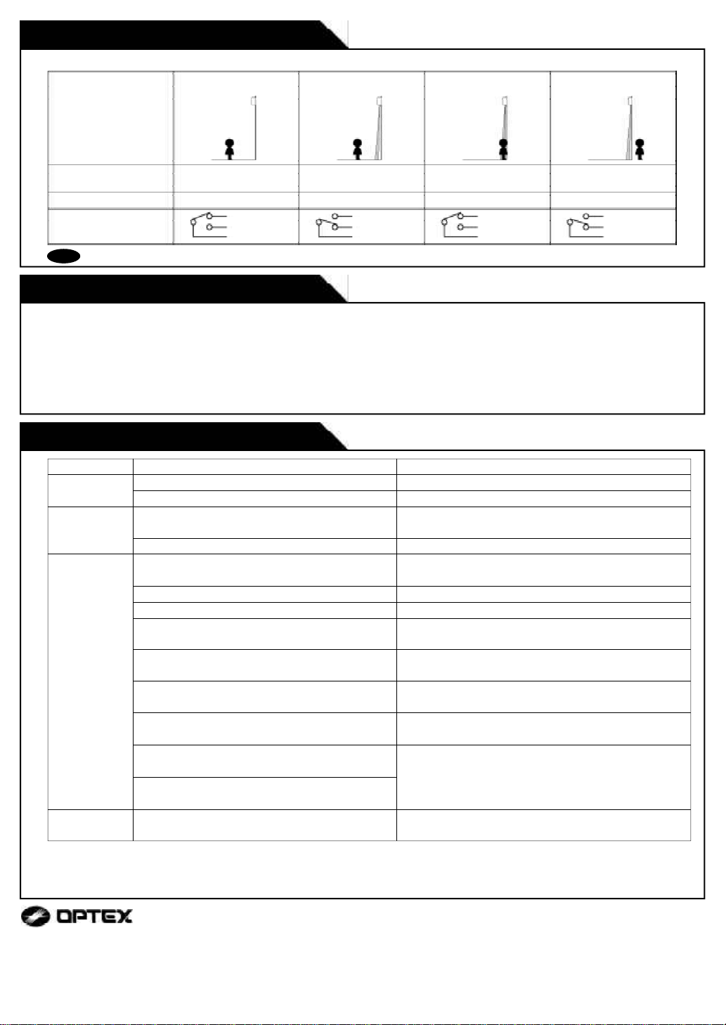
Entry motion Power OFF Outside the Detection
area
(image)
Sensor status Power OFF Stand-by
Entry into the Detection
area
Motion or Presence
Detection Active Stand-by
Red Green
Yellow
Green
White
Output
Opertion indicator Green
OFF Yellow
Green
White
Yellow
Green
White
Does not
operate
Dose not
operate
consistently
Operates by
itself
Power supply is not adequate.
Connection Failure.
Dirty detection window.
Sensitivity is Low.
There is an object that moves or emits light in the
detection area.(ex. plant, illmination etc...)
Vibration of the header.
Sensitivity is high.
Waterdrops on detection window.
Detection area has interfered the area of
another sensor.
The Emitting spots are overlapping with the door
/ header.
Keep
operating
There is an reflected object in the detection area.
Solar light reflects.
Presence timer is Infinity. There was an abrupt
condition change in the detection area.
Adjust to stated voltage.
Check the wiring and the connector.
Wipe the detection window with a damp cloth( Do not
use any cleaner or solvent ).
Set the Sensitivity Switch “ H ” .
Set the Sensitivity Switch “ L ” .
Remove the object.
Remove the object.
Secure the header. Or set the Sensitivity Switch “ L ” .
Install in a place keeping the waterdrops off. OR
use a rain-cover (Optional).
Set the different frequency position each other.
Adjust the detection area to deep (outside).
Turn the power off and on again.
Trouble Possible Cause Solution
CHECKING
Check the operation according to the chart below.
There was a puddle left by rain or snow.
The floor has gotten wet.
The exhaust of the car and the fog penetrate into
the detection area.
This sensor is equipped with the anti-malfunction.
However, pay attention when installing as malfunction
may occur under the left conditions.
Yellow
Green
White
Outside the Detection
area

Other Optex Accessories manuals

Optex OA-FLEX AIR T User manual

Optex

Optex OA-FLEX AIR T User manual

Optex SIP-3020/5 User manual

Optex

Optex SIP-3020/5 User manual

Optex BGS-V2000 Series User manual

Optex

Optex BGS-V2000 Series User manual

Optex Pro Swing PREMIER T User manual

Optex

Optex Pro Swing PREMIER T User manual

Optex RC-20U User manual

Optex

Optex RC-20U User manual

Optex GEN-DC User manual

Optex

Optex GEN-DC User manual

Optex Elite OA-603 User manual

Optex

Optex Elite OA-603 User manual

Optex OA AXIS T User manual

Optex

Optex OA AXIS T User manual

Optex i-OneX T User manual

Optex

Optex i-OneX T User manual

Optex AX-250PLUS User manual

Optex

Optex AX-250PLUS User manual

Optex OA-AXIS T User manual

Optex

Optex OA-AXIS T User manual

Optex Pro Swing Elite ST User manual

Optex

Optex Pro Swing Elite ST User manual

Optex V2 Series User manual

Optex

Optex V2 Series User manual

Optex ViiK Exposed Type OVS-02GT Series User manual

Optex

Optex ViiK Exposed Type OVS-02GT Series User manual

Optex OVS-01GT User manual

Optex

Optex OVS-01GT User manual

Optex OAM-DUAL II User manual

Optex

Optex OAM-DUAL II User manual

Optex OA-4500S(E) User manual

Optex

Optex OA-4500S(E) User manual

Optex OA-FLEX T User manual

Optex

Optex OA-FLEX T User manual

Optex OA-203C User manual

Optex

Optex OA-203C User manual

Optex TS-1000-D User manual

Optex

Optex TS-1000-D User manual

Optex CVS2 User manual

Optex

Optex CVS2 User manual

Optex OA-PRESENCE T Installation manual

Optex

Optex OA-PRESENCE T Installation manual

Optex OA-4500S User manual

Optex

Optex OA-4500S User manual

Optex Accurance-3D A3001CB Manual

Optex

Optex Accurance-3D A3001CB Manual

Popular Accessories manuals by other brands

PPA TOMADA 10A SMART manual

PPA

PPA TOMADA 10A SMART manual

Festo SFAH Description

Festo

Festo SFAH Description

Mantra MIS100V2 instruction manual

Mantra

Mantra MIS100V2 instruction manual

Honeywell CAMIR-F1 Quick installation guide

Honeywell

Honeywell CAMIR-F1 Quick installation guide

Tippkemper CNS-SV 25 T quick start guide

Tippkemper

Tippkemper CNS-SV 25 T quick start guide

Campbell CS240 product manual

Campbell

Campbell CS240 product manual

Energenie ENER010 quick start guide

Energenie

Energenie ENER010 quick start guide

Samsung XE800ZAA user manual

Samsung

Samsung XE800ZAA user manual

Huawei BTS3900 V100R003 Hardware description

Huawei

Huawei BTS3900 V100R003 Hardware description

Zadez RWP-535 Manual book

Zadez

Zadez RWP-535 Manual book

T3 T3-Smart-301 user manual

T3

T3 T3-Smart-301 user manual

Panasonic MA3S781DG Specification sheet

Panasonic

Panasonic MA3S781DG Specification sheet

ABB AP300 user guide

ABB

ABB AP300 user guide

Cardinal 205 Installation and technical manual

Cardinal

Cardinal 205 Installation and technical manual

Baltimore Aircoil Company TrilliumSeries TRF Operation & maintenance manual

Baltimore Aircoil Company

Baltimore Aircoil Company TrilliumSeries TRF Operation & maintenance manual

Omegon EQ-500 X instruction manual

Omegon

Omegon EQ-500 X instruction manual

Whale INSTANT MATCH SDP134T Installation guidelines

Whale

Whale INSTANT MATCH SDP134T Installation guidelines

Infinite L-com SRCN-C711-1 user guide

Infinite

Infinite L-com SRCN-C711-1 user guide

manuals.online logo
manuals.online logoBrands
  • About & Mission
  • Contact us
  • Privacy Policy
  • Terms and Conditions

Copyright 2025 Manuals.Online. All Rights Reserved.