Jiajia AUDI Q7 SUV Datasheet

AUDI Q7 SUV RIDE ON
Owner’s Manual
with Assembly Instructions
Styles and colo(u)rs may vary.
Made in China.
The owner’s manual contains important safety information as well as assembly, use and
maintenance instructions.
The Ride-on Car must be assembled by an adult who has read and understands the
instructions in this manual.
Keep the package away from children and dispose of properly before use.
Keep this manual for future reference.

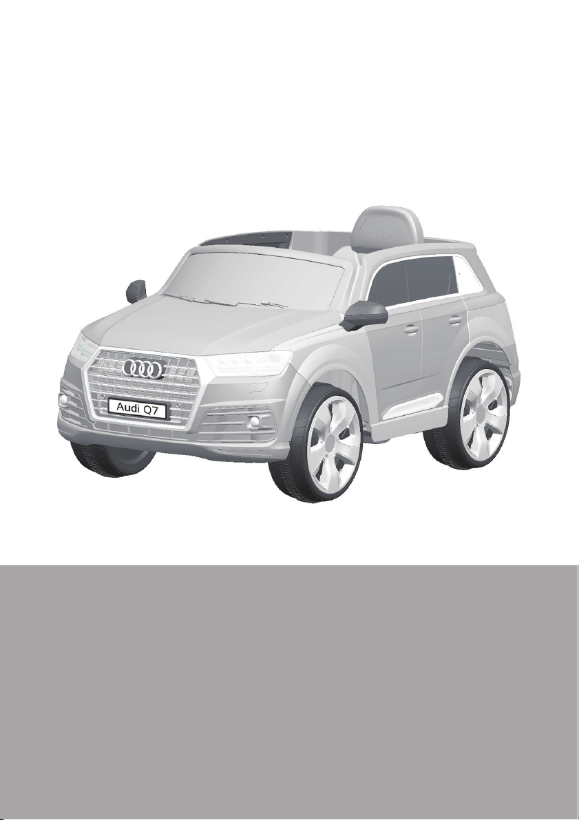
On the purchase of your new AUDI Ride-On.
This ride-on car will provide your child with many miles of riding of
enjoyment. To help assure you and your rider a safe ride we ask you to
please read this manual carefully, and keep it for future reference.
Follow the recommendations in this manual, they are designed to improve
the safety and operation of your ride-on car and it’s rider.
Battery
Charger
6V7Ah*1 or 6V10 *1
6V1000mA
6V7Ah*2
12V1000mA
Suitable age:
Load Capacity:
Speed:
Size of car:
Power way:
Charge time:
37~96 Months
Under 30 kgs
1WD: 2.5 km/h 2WD:2.5~5 km/h
121 x 72 x 59 CM
Charging type
8 ~ 12 hours
About Your New Ride-On │1
VER: SMS-JJ2188-EN-160523
Audi Q7 Electric Ride-on manufactured by Zhejiang Jiajia Ride-on
Co.,Ltd. (Address: Xincang Industrial Zone, Xincang Town, Pinghu
City, Zhejiang Province, China). Trademarks, design patents and
copyrights are used with the approval of owner AUDI AG.

1
2
3
4
5
6
7
8
9
10
11
12
13
14
15
16
17
18
19
20
21
22
23
24
1
1
1
3
1
3
1
4
2
1
2
1
1
6
1
1
1
1
1
1
2
1
1
2
2
2
2
2
2
2
8
PART
NO.
REMARKS
PART NAME
Q’ty (pcs)
Vehicle body
Gear box
Driving wheel
Normal wheel
Bush
Ø12 washer
Motor hodd
Ø4x12 flat head screw
Mirror
Seat
Ø4x12 round head screw
Rear axle
Front axle
Steering column
M5x35 machine screw
Ø5 nut
R/C driver
Ø5 nut
M5x22 machine screw
Split pin
Ø10 washer
Charger
Remote controller
Spanner
Placed on the steering wheel
Left and right
One labeled “L”, and the other one labeled “R”
1WD
2WD
2WD
Parts List │2
IF EQUIPPED, for R/C type only

22
23
24
20 21
21
9
12
13
1
7
32
56
4
817
10 11 14
19 18
15 16
HINT: Some parts shown are assembled on both sides of vehicle
Parts Diagram │3
Normal Type
R/C Type
CONTROLLER STYLES MAY VERY

Before Assembly │4
• Make sure that the power switch is turned “OFF” before assembling the ride-
on.
• Before first time use, charge the battery for at least 4 to 6 hours.
• Assembly tools required:
WARNING!
Screwdriver
(not included)
Long nose pliers
(not included)
Spanner
(If equipped)
●Non-rechargeable batteries are not to be recharged.
●Rechargeable batteries are to be removed from the toy before being charged.
●Rechargeable batteries are only to be charged under adult supervision.
●Different types of batteries or new and used batteries are not to be mixed.
●Batteries are to be inserted with the correct polarity.
●Exhausted batteries are to be removed from the toy.
●The supply terminals are not to be short-circuited.
BATTERY INFORMATION
• CHOKING HAZARD - Small parts. Not suitable for children under 36 months.
The product contains small parts, keep children away when assembling.
• ADULT ASSEMBLY REQUIRED.
• Always remove protective material and poly bags and dispose before assembly.

1
1
Remove all the parts from the rear axle.
1. Insert the rear axle into the hole near the rear vehicle.
Rear axle with a Ø12 washer
2WD
2
Attach the Rear Axle │5
Remove all the parts from the rear axle.
1. Slide a Ø12 washer onto the rear axle from the longer end.
2. Insert the rear axle with a Ø12 washer into the smaller hole
on the rear of the vehicle from Right Hand Side (standing at
back of vehicle).
1WD

2
3
4
10
7
6
5
1
HINT: If your vehicle is Two Wheels Driving Type, see the next page please.
8910
Attach the Rear Wheels │4
Driving Wheel
Normal Wheel
1WD
Rear axle
1. Slide the gear box onto the rear axle (Left Side). Keep the motor and the connector on
the gear box through the larger hole on the rear vehicle and out where the battery sits.
2. Slide the driving wheel onto the rear axle. And keep the driving wheel match with the
gear box.
3. Slide the Ø12 Washer onto the rear axle.
4. Tighten a Lock nut to the end of the rear axle with a spanner.
5. Slide the Ø12 Washer onto the rear axle (Right Side).
6. Insert the bush into the hole in the center of the normal wheel.
7. Slide the Normal wheel onto the rear axle.
8. Slide the Ø12 Washer onto the rear axle.
9. Tighten a Lock nut to the end of the rear axle with a spanner. HINT: An extra
spanner has been provided to hold the Lock Nut on the other side of the rear
alxe while tightening the Lock Nut on the other side.
10. Fit the hubcaps to the wheel cover.

2
3
4
5
1
Attach the Rear Wheels │6
2WD
Driving Wheel
Rear axle
1. Slide the gear box onto the rear axle. “R” labeled gear box should be fit to the
“R” side of vehicle body; “L” labeled gear box should be fit to “L” side of vehicle
body. Keep the motor and the connector on the gear box through the larger
hole on the rear vehicle and out where the battery sits.
2. Slide the driving wheel onto the rear axle. And keep the driving wheel match
with the gear box.
3. Slide the Ø12 Washer onto the rear axle.
4. Tighten a Lock nut to the end of the rear axle with a spanner. HINT: An extra
spanner has been provided to hold the Lock Nut on the other side of the
rear alxe while tightening the Lock Nut on the other side.
Repeat the above procedure to assemble the other driving wheel.
5. Fit the hubcaps to the wheel cover.

1
2
3
4
5
6
Front axle
Attach the Front Wheels │7
Normal Wheel
Front Bottom View
Remove all the parts from the front axle.
1. Slide a Ø12 washer onto the front axle.
2. Slide the bush (ring end first) onto the front axle.
3. Slide the normal wheel onto the rear axle. And keep the normal wheel match
with the bush.
4. Slide a Ø12 washer onto the front axle.
5. Tighten a Lock nut to the end of the front axle with a spanner.
6. “Snap” the hubcap to the wheel cover.
Repeat the above procedure to assemble the other front wheel.

1
4
5
3
2
HINT: If your vehicle with the Remote Control Function, see the next page please.
Turn the vehicle body on its side.
1. Slide a Ø10 washer onto the steering column from the straight end.
2. Insert the straight end of steering column up through the hole in the front of
vehicle body from bottom side, and out through the hole in the dash.
3. Insert the bent end of steering column through the hole in the front axle
linkage.
4. Fit a Ø10 washer onto the bent end of the steering column.
5. Insert a split pin into the hole in the steering column, bend the ends of split pin
back using a long nose pliers (not included).
Attach the Steering Column │8
Normaltype
Hole in the
front axle linkage
Table of contents
Other Jiajia Toy manuals
Popular Toy manuals by other brands

Accucraft trains
Accucraft trains SOUTHERN PACIFIC 2-10-2 F4 instruction manual

Elenco Electronics
Elenco Electronics SC-300 user guide

Playskool
Playskool 6115 instructions

GREAT PLANES
GREAT PLANES FlatOut Flatana instruction manual

BUILDABLE
BUILDABLE Mini Sugar manual

WRIGHT BROTHERS
WRIGHT BROTHERS Curtiss Pusher 1911 Vintage instruction manual

Innovative Hobby Supply
Innovative Hobby Supply BK 6424 Assembly instructions

LGB
LGB 27430 instruction manual

Accucraft
Accucraft wsl 15 instruction manual

Mattel
Mattel Disney PIXAR Cars FCP09 instructions

Mega Construx
Mega Construx PRO BUILDERS HALO DKW59 quick start guide

Crayola
Crayola Glow Station On the Go quick guide