JK Audio Concierge 2x6 User manual

JK Audio
Concierge™2x6
Switch Core
User Guide

ii Concierge™ 2x6 Switch Core
Thank You
Thank you for purchasing the JK Audio Concierge 2x6 Switch Core. Please read
this guide for instructions on setting up and using your new product.
Getting Assistance
If you have technical or application questions,
call us M-F: 8:30am-5:00pm (CT)
In the US & Canada (Toll-Free)
800-552-8346 All other countries:
815-786-2929
Email us at:
Or check out our FAQ section for answers to common questions.
Limited Warranty
Concierge 2x6 is covered by a 2 year warranty to be free from defective
workmanship and materials. To obtain service, contact JK Audio by phone or
email for return authorization. Once authorized, you will carefully pack and ship
the faulty product and all accessories to us. You will pay for shipping to us and
we will pay for return back to you.
This warranty does not cover damages due to accident, weather, re, ood,
earthquake, misuse, unauthorized repairs or modications, or damages occurred
in shipping, only defective workmanship or materials.
There are no expressed or implied warranties which extend beyond the
warranty here made.
Welcome

Contents iii
Contents
Contents
Overview 1
Getting to know your Concierge™2x6 2
Getting Connected 3
Installation Options 4
Installing 8
Conguring the Concierge™ 2x6
Auto-Ring, Auto-Drop, Slave DIP Switch Controls 9
Auto-Drop & Aux Phone Control 10
Compatibility 11
Technical Information 12
Declaration of Conformity 14
FCC Compliance 15

iv Concierge™ 2x6 Switch Core
Product Registration / Firmware Updates
Your Concierge system contains many advanced features, but we are constantly
looking for ways to improve. Product Registration allows us to keep you informed
of any rmware updates that become available in the future. Concierge allows
program updates through the USB port, using simple programming instructions.
Please register your purchase by sending an email to:
Subject: Product Registration
Be sure to include your serial number, name, email address and mailing address.
STOP

Overview 1
Introducing the Concierge™ 2x6
The Concierge™ 2x6 switch core allows connection of two hybrids across six
phone lines. The switch matrix routes six incoming analog phone lines to either
one or two JK Audio innkeeper 1rx™ single channel Digital Hybrids, or one
innkeeper 2™ Digital Hybrid. A rmware upgrade is all that is required to make
most older model INN 1x/INN 1rx and INN 2 hybrids compatible with this new
system. See page 11 for innkeeper compatibility.
Concierge adds music on hold input, auxiliary phone integration, and intuitive
call control. The end result is a powerful, exible system featuring excellent call
screening capabilities, while allowing two studios to share the phone lines.
Two Concierge switch cores can be bridged together, providing six additional
phones lines for a 2 hybrid, 12 line system.
Up to eight Guest Module control surfaces can be added to provide remote
control of the switch matrix over CAT5 cable. Guest Modules are hot swappable
without losing calls, and feature line selection buttons that change color to
indicate call status. Guest Modules are available in GM1x6, GM2x6, and GM1x12
desktop and rack mount versions.
The smallest system consists of one Concierge switch core, one innkeeper 1rx,
and one Guest Module GM1x6 control surface.
6 Phone Line jacks
2 Hybrid Connections
Hold Audio Input
Expandable to 2 x 12 Lines
LED Line Status Indicators
Front panel DIP Switches
Auto-Ring & Auto-Drop Controls
Overview

2Concierge™ 2x6 Switch Core
Getting To Know Your Concierge™ 2x6 Switch Core
1 2 3 4 5 6
1 2
Power Auto-Drop
Bridge
1 2
HybridGM Bus
JK AudioTM
Switch Core2x6
TM
12345678910 11 12
1 2 3 4 5 6
1 2
Power Auto-Drop
Bridge
1 2
HybridGM Bus
JK AudioTM
Switch Core2x6
TM
12345678910 11 12
123456
Phone Lines
Phones
Hybrid Remote
1
Guest Modules
1/A
Phone Ports
JK Audio, Inc.
Hold Audio
Input USB
100-240 VAC
50-60 Hz, 2.5 A
2/B
Data
Level
2x6 Switch Core
TM
2
Hybrid Aux
Expansion Bus
1/A
Hybrid Aux
2/B
1 2 3 4 5 6
Line LEDs
Each phone line port features dedicated ring detect, line current detect, polarity
reversal detect, line presence, and hold circuit. Front panel LEDs indicate various
line states. A green Line LED indicates the line is o-hook and properly wired,
while a red Line LED indicates the line is o-hook but reverse wired. In most
cases, reverse wiring will not aect system operation. The only exception is
during innkeeper 1x/1rx conferencing, where both lines are electrically bridged
together. Two lines of dierent polarity cannot be joined in a conference. It is
advised to go through each line to ensure a properly wired connection.
The Concierge front panel Line LEDs indicate when a phone line is taken o-
hook through the Concierge system. These LEDs do not indicate when a phone
line is already o-hook outside the system, or if the line is disconnected or out of
service.
Front
Back

Getting Connected 3
16 Phone Line Jacks
RJ-11C
2Row-A Phone Line to Hybrid 1
3Row-AAuxiliary Phone
4Row-B Phone Line to Hybrid 2
5Row-B Auxiliary Phone
6Expansion Bus to Second Concierge RJ-11C / RJ-45 at cable
7Hybrid Remote 1 RJ-50 at cable
8Hybrid Remote 2
9Row-A Guest Module Bus RJ-45 CAT5
10 Row-B Guest Module Bus
11 Hold Audio Input 3.5 mm
12 USB Control Port USB Type B
13 100-240 VAC Input
Getting Connected
1 2 3 4 5 6
1 2
Power Auto-Drop
Bridge
1 2
HybridGM Bus
JK AudioTM
Switch Core2x6
TM
12345678910 11 12
1 2 3 4 5 6
1 2
Power Auto-Drop
Bridge
1 2
HybridGM Bus
JK AudioTM
Switch Core2x6
TM
12345678910 11 12
123456
Phone Lines
Phones
Hybrid Remote
1
Guest Modules
1/A
Phone Ports
JK Audio, Inc.
Hold Audio
Input USB
100-240 VAC
50-60 Hz, 2.5 A
2/B
Data
Level
2x6 Switch Core
TM
2
Hybrid Aux
Expansion Bus
1/A
Hybrid Aux
2/B
7 8 9 10 11 12 13
Ports & Cable Types

4Concierge™ 2x6 Switch Core
Installation Options
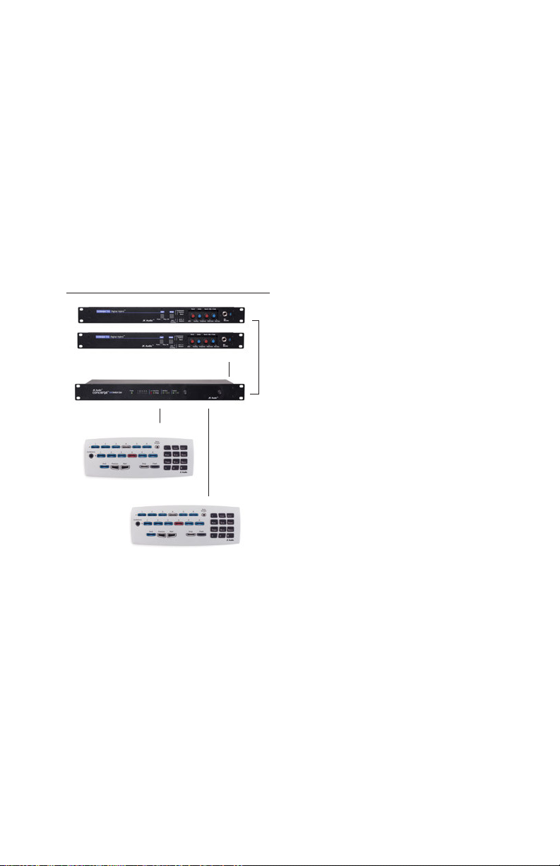
The Concierge system is very exible, oering many conguration options. The
number and type of hybrids and Guest Module control surfaces help determine
the system capabilities. It is best to look at your requirements rst, then choose
the right hybrids and controllers suitable for your unique installation.
The rst decision is whether you intend to conference two callers together,
putting both calls on the air simultaneously. This can be accomplished with a low
cost innkeeper 1x/1rx by allowing the system to combine two calls together into
one audio input on your console. Keep in mind that you will not be able to adjust
the level of the caller’s voices independently if one caller should prove quieter
than the other. Innkeeper 2 uses two separate digital hybrids to bring caller audio
into separate inputs on your console, while providing the necessary cross-
connections so everybody can hear each other.
If conferencing is not in your game plan, you may wish to keep it simple using
GM1x6 controllers. GM1x6 oers all the features of the GM2x6 without the
possible confusion of monitoring the second half of the 2x6 switch core, which
may not be a part of your installation.
Whether conferencing is in you plans or not, you might want to consider a mix of
GM1x6 and GM2x6 control surfaces depending on the location. A news studio
or call screener may not need conferencing, and may be better served by the
simpler GM1x6 control surface.
The following examples show the capabilities of each hybrid:
One innkeeper 1x/1rx™ Hybrid: pg 5
Two innkeeper 1x/1rx™ Hybrids: pg 6
One innkeeper 2™ Hybrid: pg 7

Installation Options 5
One innkeeper 1x/1rx™ Hybrid
The smallest system consists of a one line hybrid and at least one GM1x6 or
GM2x6 control surface. This is the most common system assembled when there
is only one studio and one optional screener position.
One innkeeper connects to the Hybrid 1/A jacks on the Concierge, as does at
least one Guest Module. Any GM1x6 or GM2x6 controllers connected to bus
1/A will display calls on row A of the Guest Module. A second GM1x6 or GM2x6
control surface can be connected to Guest Module control bus 2/B along with an
Auxiliary phone connected to Aux Phone Port 2/B to provide an independent call
screening position. Any GM2x6 controllers connected to bus 2/B will display calls
routed to the Aux phone on row B of the Guest Module. A GM1x6 connected to
bus 2/B will display these same calls shifted up to its top row.
Installation Options
One Studio: 1 Hybrid, 6 Lines Studio+Screener: 1 Hybrid, 6 Lines
GM2X6
GM1X6 Screener
Concierge™ 2x6
innkeeper 1rx
GM1X6
Concierge™ 2X6 BUS A BUS A
BUS B
innkeeper 1rx

6Concierge™ 2x6 Switch Core
Installation Options
Two innkeeper 1x/1rx™ Hybrids
This is a typical conguration if two studios share the same six phone lines. With
two single line hybrids, one will get connected to port 1/A and one to port 2/B.
Any GM1x6 or GM2x6 controllers connected to bus 1/A will display calls on row
A of the Guest Module. Any GM2x6 controllers connected to bus 2/B will display
calls on row B of the Guest Module. A GM1x6 connected to bus 2/B will display
these same calls shifted up to its top row.
Two separate single line hybrids allow one two-caller conference on rowAwith
one audio output, and a separate two-caller conference on row B with a separate
audio output. These conferences cannot be combined.Any lines routed to hybrid
1 cannot be accessed by hybrid 2, and vice versa.
Two Studios: 2 Hybrids, 6 Lines
Studio A GM2x6
Studio B GM2x6
Concierge™ 2x6
innkeeper 1rx (2)
BUS A
2
BUS B
1

Installation Options 7
Installation Options
One innkeeper 2™ Hybrid
While one innkeeper 2 hybrid can function as two separate hybrids as in
the previous scenario, conferencing was designed primarily for a one studio
application. The innkeeper 2 hybrid connects to the 1/Ahybrid port. The
innkeeper 2 brings row A and row B callers into the console on separate audio
channels, allowing independent level control even during conferencing.
Bus A can be used for the studio Guest Modules. Bus B can be used for a call
screener, allowing the screener access to the second hybrid channel or second
aux phone port for call screening while the studio airs calls on Bus A.
Keep in mind that when Conference is selected, both Bus A and Bus B are
joined together in a conference, and the screener no longer has the ability to
screen calls.
One innkeeper 2™ Hybrid with Two Concierge Switches
This system can be expanded to 12 lines by simply adding a second Concierge™
2x6 switch.
GM2x6
GM2x6
BUS A
BUS B
2 Hybrids, 6 Lines 2 Hybrids, 12 Lines
innkeeper 2
Concierge™ 2X6
innkeeper 2
Concierge™ 2x6
GM1x12
GM1x12
BUS A
BUS B

8Concierge™ 2x6 Switch Core
Step 1: Phone Line Wiring
Connect each phone line directly to the RJ-11 jacks on the back of the
Concierge. Auxiliary phones should be connected to the 1/A or 2/B Phone Ports
for proper system integration. Do not use external line splitters to connect an Aux
phone. Do not connect an Aux phone to the innkeeper digital hybrid.
Step 2: Hybrid Connection
Two cables join each hybrid to the Concierge Switch Core.An RJ11 Modular
phone cord connects the innkeeper Phone Line jack to the Concierge 1/A or 2/B
Hybrid Phone Port. The remote data cable connects the innkeeper remote jack to
the Concierge Hybrid Remote jack.
Step 3: Guest Module Control Surfaces
A maximum of four guest modules can be connected to each of the two
Guest Module ports, for a system maximum of eight Guest Modules. The dual
connection ports on each Guest Module allow for quick daisy-chain wiring, or
you may simply run all cables back to a terminal block to allow for point-to-point
wiring. The maximum distance from Concierge to the farthest Guest Module is a
function of the number of Guest Modules connected, as well as the the gauge of
the wire chosen. Standard 26 gauge cable can be used on runs shorter than 100
feet, but as distance and the number of units increase, you may need to consider
24 gauge CAT5 wire.
While Guest Modules use standard CAT5 cable, the communications protocol
is balanced dierential RS-485 using a custom pinout. This is not an Ethernet
connection, and should not be connected to a data hub or switch.
2x12 Expansion
Two Concierge switch cores can be bridged together into a 2x12 system,
providing six additional phone lines. Begin with both Concierge Switch Cores
powered down. On the second Concierge, DIP switch 5 must be set to the ON
position, shifting line assignment to lines 7-12. Now connect the phone and data
expansion bus cables from the rst unit to the second unit. Upon power-up, both
units will display a green “Bridge” LED indicating that they are now properly
communicating. Only GM1x12 control surfaces can be connected to a bridged
system. The GM1x12 control surfaces can be connected to either the 1/Aor 2/B
control bus on the Master (1-6) Concierge Switch Core. All hybrid and Guest
Modules connections are made through the Master Concierge unit. Only the
Phone Line and Expansion Bus jacks are used on the Slave Concierge unit.
Installation

Conguration 9
7Reserved
8Reserved
9Reserved
10 Guest Module Programming Mode
11 Switch Core Programming Mode
12 Accessory Enable (name TBD)
Dip Switches
The Concierge™ 2x6 Switch Core is equipped with 12 slide style DIP switches
located underneath the removeable cover plate on the front. Congure your
Concierge by enabling or disabling features by switching between the ON and
OFF positions for each DIP switch. The following chart shows each feature and
it’s corresponding switch.
Auto-Drop
OFF (Default):Places the current call on Hold when either a Line button,
Next, or Previous button is pressed.
ON: Will drop the current call when either a Line button, Next or Previous
button is pressed, unless the call is manually placed on Hold.
Slave
For 12-line systems:
OFF (Default): In the ‘O’ position, the Concierge behaves as the master
device, controlling the rst 6 lines.
ON:When bridging two Concierge Switch Cores, use the Expansion bus
to create a 12-Line system. Flip the Slave DIP switch to the ‘On’ position
to convert Lines 1-6 to Lines 7-12 on the second Concierge Switch Core.
Ring Count 12345678
Auto-Ring 0 OFF ON OFF ON OFF ON OFF ON
Auto-Ring 1 OFF OFF ON ON OFF OFF ON ON
Auto-Ring 2 OFF OFF OFF OFF ON ON ON ON
Auto Ring (Default = 1 Ring)
The Auto-Ring DIP switches select theAutoAnswer Ring Count whenever
the Auto Answer function is enabled. The Ring Count number is controlled
by a combination of the three Auto-Ring switches.
4
1-3
5
1Auto-Ring 0
2Auto-Ring 1
3Auto-Ring 2
4Auto-Drop
5Slave
6Reserved
Conguration

10 Concierge™ 2x6 Switch Core
Auto-Drop
Most PBX phone systems (and talk shows systems for that matter) are built
on the premise that when you are done talking to one person, and you select
a dierent line, the rst caller automatically gets disconnected. In other words,
you have to go through an extra step to place a call on hold. While this has the
distinct advantage of allowing you to get through calls quickly, you are also more
likely to accidentally lose a call. With Concierge, you have a choice:
• When Auto-Drop is ON, calls are automatically dropped after selecting a
dierent line, or using the Next and Previous buttons, unless you specically
put a call on hold.
• When Auto-Drop is OFF, calls are automatically put on hold after selecting a
dierent line, or using the Next and Previous buttons.
ATTENTION: Auto-Drop is OFF by default, it can be Enabled/Disabled by
using the DIP switch panel (see page 9).
Aux Phone Control
The use of a conventional telephone for call screening and dialing can be an
important part of any system. Concierge Aux Phone jacks provide seamless call
control, allowing the phone to become an integral part of the system.
The Aux Phone takes precedence over the hybrid, similar to picking up the
handset during a speakerphone call. Picking up the handset of a phone
connected to an Aux Phone jack during a call, will disconnect the Hybrid and
connect the Aux phone to the phone line. This is true in all cases except when
using an INN2 in Conference mode, when nothing will happen until one of the
two phone lines is selected.
The Aux Phone will follow these basic rules:
• If a phone connected to the Aux jack is o-hook before a line select button is
pressed, the line will be connected to the phone instead of the hybrid.
• If a call is routed to the hybrid and the phone is taken o-hook, the phone will
take control of the call.
• If the Aux Phone is not present, or on-hook, pressing a line select button will
connect that line to the hybrid.
• If the Aux Phone is connected to a port where no hybrid is connected, and the
phone is on-hook, pressing a line button does nothing.
• If auxiliary phones are part of your system, they should be connected to the
1/A or 2/B Phone Ports for proper system integration. Do not use external line
splitters to connect an Aux phone to any other port. Do not connect an Aux
phone directly to the innkeeper digital hybrid.
Auto-Drop & Aux Phone Control

Compatibility 11
Compatibility
Innkeeper Compatibility
Concierge communicates with the innkeeper 1x,/1rx, or innkeeper 2 Digital Hybrid
over a serial data port. Some early innkeeper models may require a rmware
upgrade to become compatible. Contact [email protected] for a rmware
upgrade.
Model Serial Number Status
innkeeper 1x
Before IN1X01336 Not compatible
Between IN1X01336 - IN1X02185 Requires rmware update
After IN1X02185 Compatible
innkeeper 1rx
Before IN1RX01936 Not compatible
Between IN1RX01936 - IN1RX02748 Requires rmware update
After IN1RX02748 Compatible
innkeeper 2 Before IN201729 Requires rmware update
After IN201728 Compatible
Phone Line Compatibility
Concierge works with standard POTS (Plain Old Telephone Service), PSTN
(Public Switched Telephone Network) phone lines. The phone line ports have
been tested and approved for most international POTS/PSTN line conditions, ring
patterns, voltages and frequencies, as well as call disconnect signaling. Concierge
also works on most analog line ports from PBX or VoIP phone systems, however
these systems are not required to adhere to the specications of the POTS/PSTN
network. PBX/VoIP analog line ports may need additional settings adjustments
through your system administrator or installer.

12 Concierge™ 2x6 Switch Core
Technical Information
Specications
Phone Lines (6)
Connector RJ-11C
Isolation 1500 VAC
Ringer 0.5B REN
Hold Audio Line Input
Connection 3.5mm mono
Impedence 20k ohms
Level (-10 dBu) nom.
USB
Connector Type B
Standard v2.0
Power
Power 120-240 VAC, 50-60 Hz,
25 Watts max
Connector IEC320-C14
Dimensions
Size 1.75” x 7.3” x 19” ( 4.5 x 18.6 x 48.3 cm )
Weight 5.4 pounds ( 2.4 kg )

Technical Information 13
Technical Information
RJ11
DC &
Ring
Detect
DC &
Ring
Detect
DC &
Ring
Detect
DC &
Ring
Detect
DC &
Ring
Detect
DC &
Ring
Detect
RJ11 RJ11 RJ11 RJ11 RJ11
Bus A
Bus B
Coupling
Transformer
Coupling
Transformer
Coupling
Transformer
Coupling
Transformer
Coupling
Transformer
Coupling
Transformer
Hold
Audio
DC
Supply
DC
Supply
RJ11
RJ11
RJ11
RJ11
Aux
Phone
Aux
Phone
Hybrid 1 Hybrid 2
Loop
Current
Detect
Loop
Current
Detect

14 Concierge™ 2x6 Switch Core
Declaration of Conformity
Manufacturer’s Name
Manufacturer’s Address JK Audio, Inc.
1311 E 6th Street
Sandwich, Illinois 60548 USA
Declares that the product:
Product Name
Model Numbers Concierge™ 2x6 Switch Core
CON2X6
Conforms to the following Product Specications:
Safety: AS/NZS 60950.1:2011
EN 60595-1:2006/A11:2009/A1:2010
UL Standard 60950-1 2nd edition
ESD: EN 55024:1998
EN 61000-3-2
EN 61000-3-3
Emissions:
EN 55022:1998
AS/NZS CISPR 22 (2002)
FCC Part 15, Subpart B
ICES-003
Telecom AS/CA S002:2011
FCC CFR 47, Part 68
TIA-968-B, TIA-1096-A
Supplementary Information:
The product herewith complies with the requirements of the following Directives and
carries the CE marking accordingly:
LVD 2006/95/EC (Safety)
R&TTE 1999/5/EC (Telecom)
EMC 89/336/EEC (EMC)
RoHS Directive 2015/863
The Technical File containing supporting documentation is maintained at:
JK Audio, Inc (Corporate Headquarters)
Compliance Manager
1311 E 6th Street
Sandwich, Illinois 60548 USA
815-897-2929 phone
815-786-8502 fax

FCC Compliance Notice 15
FCC Part 15 Compliance
This device complies with Part 15, Subpart B of the FCC Rules. Operation is subject to
the following two conditions: (1) This device may not cause harmful interference, and (2)
this device must accept any interference received, including interference that may cause
undesired operation.
This equipment has been tested and found to comply with the limits for a Class Adigital
device, pursuant to Part 15 of the FCC Rules. These limits are designed to provide
reasonable protection against harmful interference when the equipment is operated in a
commercial environment. This equipment generates, uses, and can radiate radio frequency
energy and, if not installed and used in accordance with the instruction manual, may cause
harmful interference to radio communications. Operation of this equipment in a residential
area is likely to cause harmful interference in which case the user will be required to correct
the interference at his own expense.
Changes or modications not expressly approved by JK Audio can void the user’s authority
to operate the equipment.
FCC Registration
Your new JK Audio product has been registered with the Federal Communications
Commission (FCC). This product complies with the standards in Part 68 of the
FCC rules.
1. Connection And Use With The Nationwide Telephone Network
The FCC requires that you connect this telephone equipment to the national telephone
network through a USOC RJ-11C modular telephone jack. This equipment may not be
used with Party Line Service or Coin Telephone Lines. This equipment is hearing aid
compatible.
2. Information For The Telephone Company
Upon request from your local telephone company, you are required to provide the
following information: a) The "line" to which you will connect the telephone equipment
(that is, your telephone number), and b) The telephone equipment's FCC registration
number. This can be found on the bottom of your telephone equipment, and, c) The
ringer equivalence number (REN) for this equipment. The REN is used to determine the
quantity of devices which will be connected to the telephone line. Excessive RENs on the
telephone line may result in the devices not ringing in response to an incoming call. In
most, but not all areas, the sum of the RENs should not exceed 5.0. To be certain of the
number of devices that may be connected to the line, as determined by the total RENs,
contact the local telephone company.
3. Repair Instructions
If it is determined that your telephone equipment is malfunctioning, the FCC requires that
it not be used and that it be unplugged from the modular outlet until the problem has been
corrected. Repairs to this telephone equipment can only be made by the manufacturer
or its authorized agents or by others who may be authorized by the FCC. For repair
procedures, follow the instructions outlined under the warranty section of the manual.
4. Rights Of The Telephone Company
If telephone equipment is causing harm to the network, the telephone company may
temporarily discontinue your telephone service. If possible, they'll notify you before they
interrupt service. If advanced notice isn't practical, you'll be notied as soon as possible.
You'll be given the opportunity to correct the problem, and you'll be informed of your
right to le a complaint with the FCC. Your telephone company may make changes in its
facilities, equipment, operations or procedures that could aect the proper functioning of
your JK Audio product. If such changes are planned, you'll be notied by your telephone
company.
FCC Compliance Notice

JK Audio, Inc.
1311 E 6th St.
Sandwich, IL 60548
United States
Telephone: 815.786.2929
Toll Free: 1.800.jkaudio
Fax: 815.786.8502
www.jkaudio.com
© 2019 JK Audio, Inc. All rights reserved.
Concierge™ 2x6
Switch Core
User Guide Version 6/21/19
JK Audio
Other manuals for Concierge 2x6
2
Table of contents
Other JK Audio Switch manuals
Popular Switch manuals by other brands

Murphy
Murphy TATTLETALE MS2100 Typical Wiring Tech Sheet

Octava
Octava HDMX44-V1.3 installation guide

Silicon Graphics
Silicon Graphics VBOB owner's guide

Gefen
Gefen EXT-DVIKVM-241DL user manual

Moxa Technologies
Moxa Technologies TN-4516A non-PoE series Quick installation guide

Asus
Asus GigaX 1016 user guide

Supermicro
Supermicro SSE-G3648B installation guide

North Star
North Star 8000i installation manual

SMC Networks
SMC Networks ISA3 Operation manual

Mastervolt
Mastervolt MASS SYSTEMSWITCH 10 User and installation manual

Fortinet
Fortinet FortiSwitch-548B v. 5.2.0.2 Administration guide

Pakedge Device & Software
Pakedge Device & Software SK24 user manual