JK-Global Service GmbH Seite 3 von 17 Stand: 20.09.04
Teilenr.: 801506 Order no.: 801506
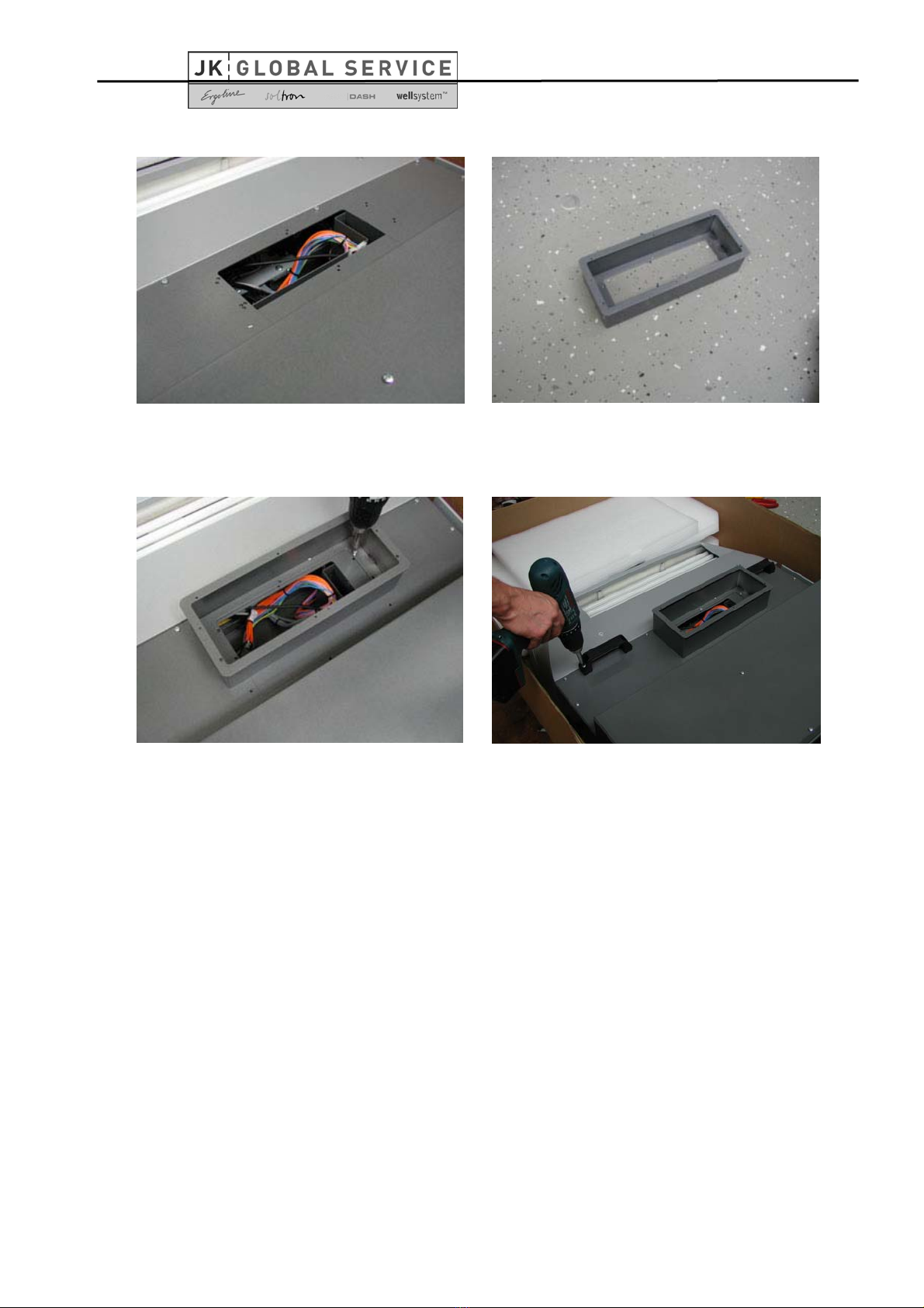
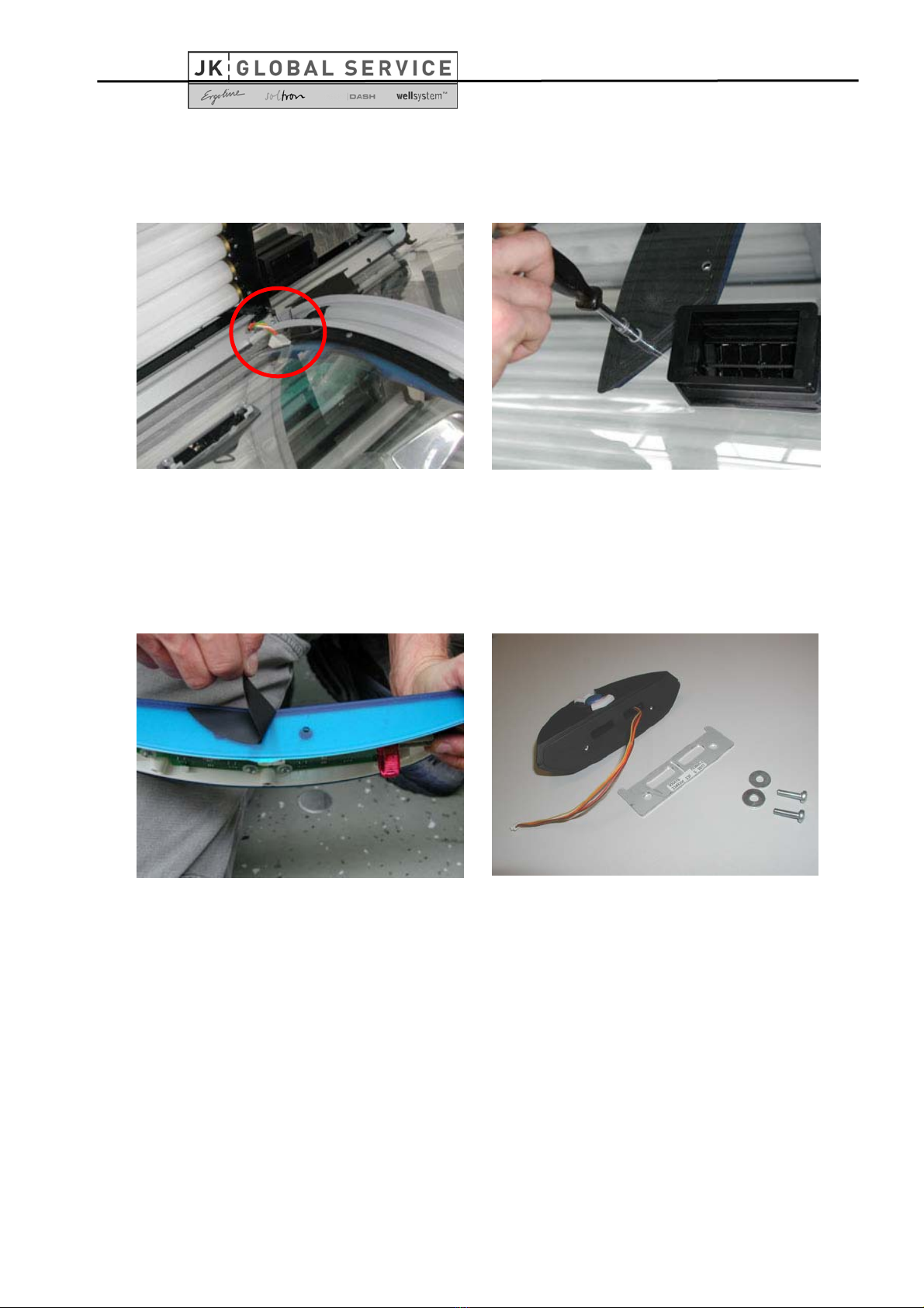
Schritt 5/ Step 5
Geöffnete Abdeckung der Multivisionseinheit.
Opened covering of the multivision unit.
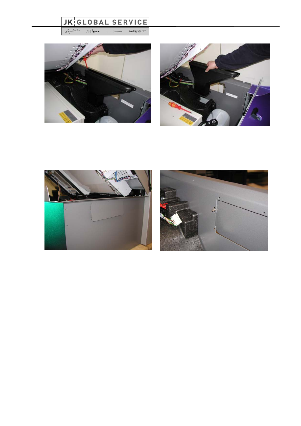
Schritt 6/ Step 6
Entpacken Sie den Anschlussstutzen.
Unpack the connection socket.
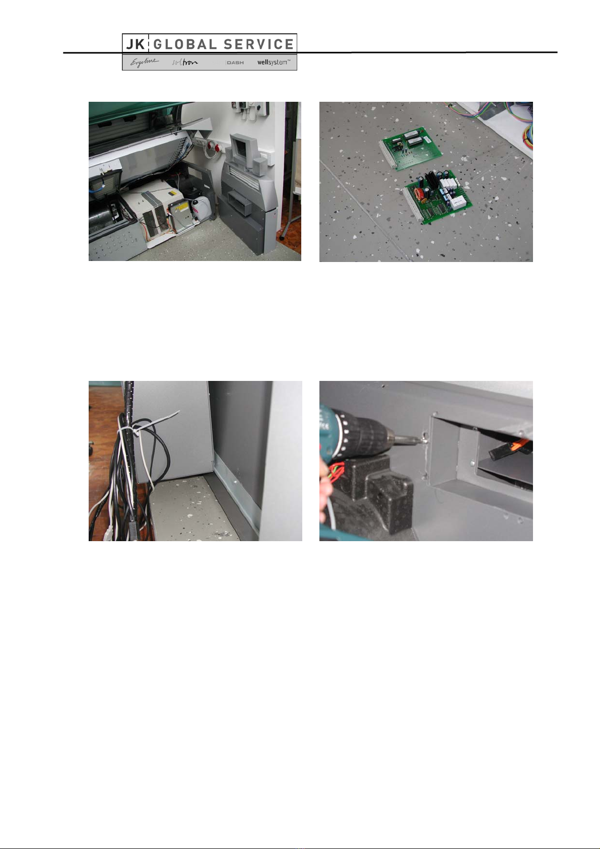
Schritt 7/ Step 7
Montieren Sie den Anschlussstutzen an die
Multivisionseinheit mit den beigefügten Schrau-
ben. Beachten Sie dabei die richtige Position des
Anschlussstutzens.
Mount the connection socket to the multivision
unit with help of the supplied screws. Please
observe the correct positioning of the air
discharge socket.
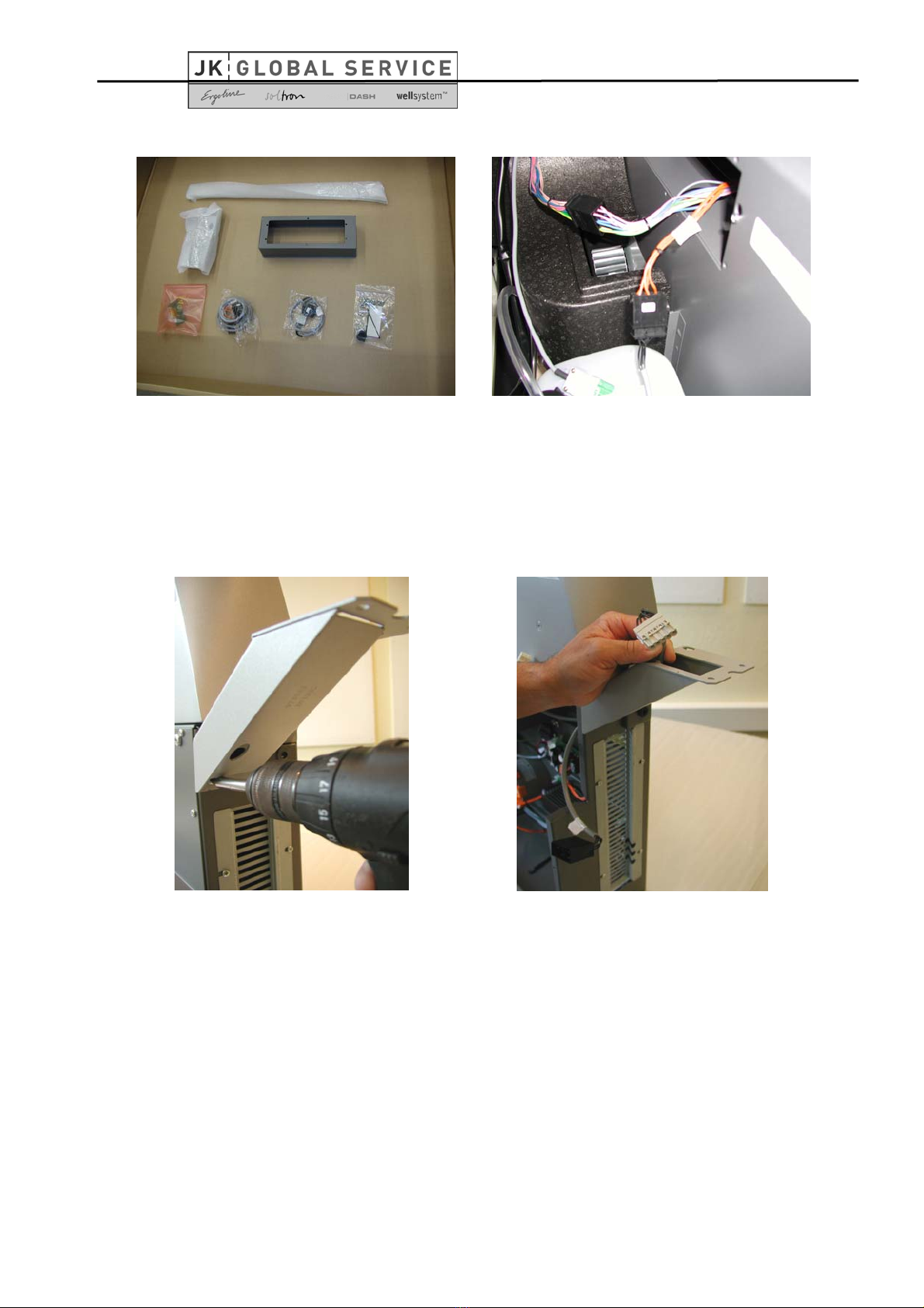
Schritt 8/ Step 8
Um die Multivisionseinheit einfacher transpor-
tieren zu können, ist es möglich zwei Handgriffe
an das Gehäuse zu schrauben.
Diese Handgriffe sind nicht im Lieferumfang
enthalten und können separat bestellt werden.
Diese werden danach wieder entfernt werden.
Diese können dann für spätere Montagen weiter
benutzt werden.
To facilitate the transport of the multivision unit
you can screw to handles to the housing.
Afterwards, these should be removed. They can
again be used for future transports/assemblies.