
Computer Instruction
FUNCTIONS
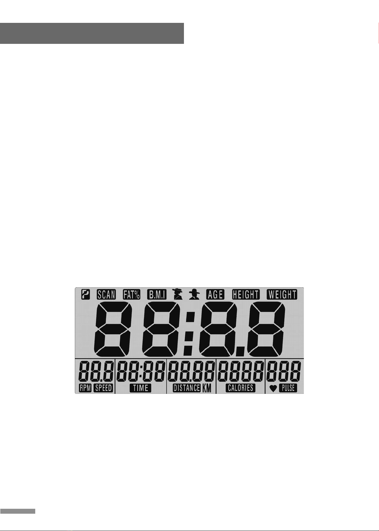
Scan
Automatically scan through each mode in sequence every 6 Seconds. The display loop
is scan-speed-rpm(if have)-time-distance-Calorie-pulse-scan on the main screen.
Speed
Displays current training speed, the maximum is 99.9km/ml.
Rpm
Displays current rotation per minute. Rpm and speed will switch to Another display in
every 6 seconds after exercise starts.
Time
Accumulates workout time from 0:00 up to 99:59. The user may Preset target time by
pressing up and down button. Each increase Ment is 1 minute.
Distance
Accumulates total distance from 0.00 up to 99.99 km or mile. The user May preset target
distance data by pressing up and down button. Each increase ment is 0.5 km or mile.
Calories
Accumulates calories consupmtion during training from 0 to the Maximum 9999 cal.
(this data is a rough guide for comparison of Different exercise sessions which can not
be used in medical Treatment.)
Pulse
The monitor will display the user's heart rate while exericing.
Gripped sensor pulse function description:
You will see your current heart rate (bpm) display on the lcd During exercising. When
you start to exercise, you have to hold on Grips with both hands,after 30 seconds to to
max. 1 minute, the Pulse figure will display on the lcd. If you hold on the grip with one
Hand only, the pulse figure display will become unstable. For the Pulse readout
accuracy reason, we'll suggest you to hold on both Hands during exercising. You may
also preset target pulse to assist Training. As soon as your current heart rate is exceed
the target Figure, the monitor starts to alarm to remind the user.
Recovery
After exercising for a period of time, keep holding on grips and Press "recovery" button,
the monitor will stop all the function Display except "time" which will keep counting from
00:60 - 00:59 - 00:58 - . Down to 00:00. As soon as 00:00 is achieved,the bottom area
will show Your heart rate status with grade f1,f2, to f6. F1 is the best, and f6 Is the worst.
The user may keep exercising to improve the heart rate Status (recovery result) day by
day from f6 up to f1.** press the "recovery" button again to return to the main display.
Body fat
In stop mode ,press the body fat button to start body fat Measurement. During
measuring, user have to hold both hands on Handgrip. And the lcd display"- - - -" for 8
seconds until monitor Finish meauring. Lcd will display body fat percentage,bmi for 30
Seconds ** press the "body fat" button again to return to the main Display.
Note
1. When user stop pedaling for 4 minutes,computer will enter into Power save mode, all
setting and exercise data will stored until User start exercise again.
2. If improper display on moniter, please re-install batteries to have A good result.
3. Battery spec: 1.5v um-3 or aa(2pcs).
7


 Service manual")


