JMA Wireless MX User manual

81900523 Rev. A
©2021 JMA Wireless. All rights reserved. This document contains proprietary information. All products, company names, brands, and logos are trademarks™or
registered® trademarks of their respective holders. All specifications aresubject to change without notice.Revised: November 12, 2021
+1 315.431.7100 customerservice@jmawireless.com
Installation Guide
MX/MC
Model
Bracket
JMA Wireless World
Headquarters
7645 Henry Clay Boulevard
Liverpool, NY 13088
USA
www.jmawireless.com
+1 888-201-6073
Instructions for extension kit
for MX08FIT265-01
P/N 81900523
10
Rev. Description EC number
A Release 77297
*longer configuration shown
B Updated BOM 77464 ECR01729

81900523 Rev. A
©2021 JMA Wireless. All rights reserved. This document contains proprietary information. All products, company names, brands, and logos are trademarks™or
registered® trademarks of their respective holders. All specifications aresubject to change without notice.Revised: November 12, 2021
+1 315.431.7100 customerservice@jmawireless.com
Installation Guide
MX/MC Model Brackets
Instructions for extension kit for MX08FIT265-01
Kit #91900330: MX08FIT265-01 extension
bracket kit
Item
#
Part # Description Qty.
in kit
145700384-01 Back grip bracket 2
234200019-04 3/8” lock washer, HDG 29
345700382-01 Single mount adapter 2
445700391-01 Negative degree adj. bottom
bracket 2
545700385-01 Anti-rotation bracket 2
641100318-01 Threaded rod 4
734200035-01 3/8” bolt, HDG 21
845700380-01 Antenna linkage arm
mounting bracket 2
945700563-02 MX08 extension bracket,
long 4
10 45700381-01 Tilt select arm mounting
bracket 2
11 34200018-05 3/8” flat washer, HDG 54
12 34200017-09 3/8” hex nut, galv. 33
13 45700563-01 MX08 extension bracket,
short 4
NOTE: These item numbers refer to Figures 4 and 5 on pages 6
and 7. Item 9 is interchangeable with Item 13, depending on
the length of the bracket you wish to use.
Other key details:
▪The brackets were designed to handle pole diameters ranging from
2.5 to 4.5 inches.
▪When tightening all hardware, use the torque setting 20 lbf·ft.
This is the installation guide for the extension kit for the
MX08FIT265-01 antenna. This kit allows the antenna to be
either in-line or above the other macro antennas mounted
adjacent to it, which helps to avoid pattern interference.
Below is the bracket kit included with the antenna.
2 3
81900523 Rev. A
©2021 JMA Wireless. All rights reserved. This document contains proprietary information. All products, company names, brands, and logos are trademarks™or
registered® trademarks of their respective holders. All specifications aresubject to change without notice.Revised: November 12, 2021
+1 315.431.7100 customerservice@jmawireless.com
Installation Guide
MX/MC Model Brackets
Instructions for extension kit for MX08FIT265-01
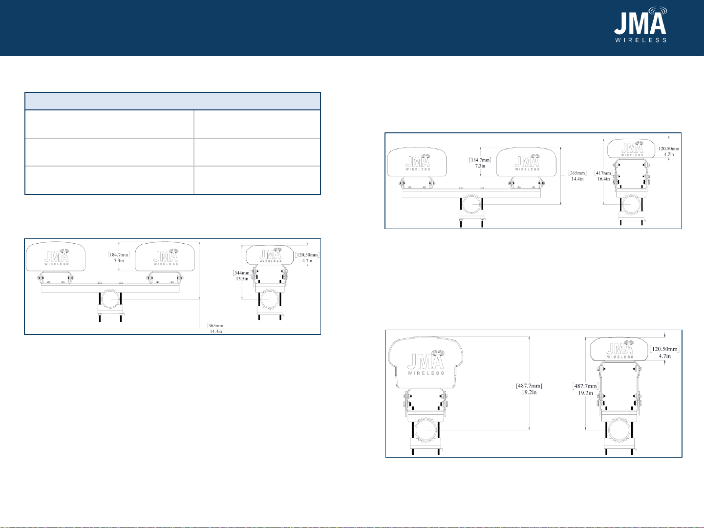
Bracket height differences:
Figure 1: With the 91900318 standard macro bracket kit
(bracket attached to 4.5” diameter pole in this example)
4 5
Figure 2: With the 91900330 extension kit using a shorter bracket
45700563-01 (bracket attached to 4.5” diameter pole in this
example)
The shorter bracket in this kit, 45700563-01, will be used to bring the
MX08FIT265-01 in line with all the MX10 antenna series (7.5” depth) as
shown below in Figure 2. This will allow the MX08FIT265-01 to be at a
total height of 16.4” from the center of the pole.
Figure 3: With the 91900330 extension kit using a longer bracket
45700563-02 (bracket attached to 4.5” diameter pole in this
example)
The longer bracket in this kit, 45700563-02, will be used to bring the
MX08FIT265-01 in line with all the Gen 2 MX06 antenna series (10.7”
depth) as shown below in Figure 3. This will allow the MX08FIT265-01
to be at a total height of 19.2” from the center of the pole. This works
with single-mount bracket kits or dual-mount brackets for the Gen 2
MX06 antenna series.
Bracket kit Total height of MX08
Standard bracket kit
(See Figure 1)13.5”
91900330 using 45700563-01
(shorter bracket) (See Figure 2)16.4”
91900330 using 45700563-02
(longer bracket) (See Figure 3) 19.2”
Table 1: Bracket differences
MX08FIT265-01
MX08FIT265-01
MX08FIT265-01
Example: MX10 series
Example: MX10 series
Example: MX06 series

81900523 Rev. A
©2021 JMA Wireless. All rights reserved. This document contains proprietary information. All products, company names, brands, and logos are trademarks™or
registered® trademarks of their respective holders. All specificationsare subject to change without notice.Revised: November 12, 2021
+1 315.431.7100 customerservice@jmawireless.com
Installation Guide
MX/MC Model Brackets
Instructions for extension kit for MX08FIT265-01
Attach bottom bracket to antenna
1. Install bottom mount pieces—back grip bracket 1, anti-rotation
bracket 5, single mount adapter 3, bottom bracket 4, and MX08
extension bracket 9 (highlighted blue)—onto antenna as shown in
Figure 4 using threaded rods 6 and the following 3/8” hardware: 2,
7, 11, and 12.
6 7
Figure 4: Bottom mount
2. Connect the single mount adapter 3 and bottom bracket 4 using the
hole labelled “0.” If you need to do a -1oor -2otilt, use the labeled
holes on the bottom bracket plate. Leave the fasteners associated
with tilt and pole loose enough to allow free rotation of the parts.
Make sure the threaded rods do not extend past the nut closest to
the antenna.
Figure 5: Top mount
Attach top bracket to antenna
3. Install top mount pieces—back grip bracket 1, anti-rotation bracket
5, single mount adapter 3, antenna linkage arm 8, tilt select arm
10, and MX08 extension bracket 9 (highlighted blue)—onto antenna
as shown in Figure 5 using threaded rods 6 and the following 3/8”
hardware: 2, 7, 11, and 12.
4. Fasten antenna linkage arm 8 and tilt select arm 10 together using
holes “C” and “1” for default tilt. Leave all fasteners associated with
tilt and pole loose enough to allow free rotation of the parts. Make
sure the threaded rods do not extend past the nut closest to the
antenna.
81900523 Rev. A
©2021 JMA Wireless. All rights reserved. This document contains proprietary information. All products, company names, brands, and logos are trademarks™or
registered® trademarks of their respective holders. All specificationsare subject to change without notice.Revised: November 12, 2021
+1 315.431.7100 customerservice@jmawireless.com
Installation Guide
MX/MC Model Brackets
Instructions for extension kit for MX08FIT265-01
8
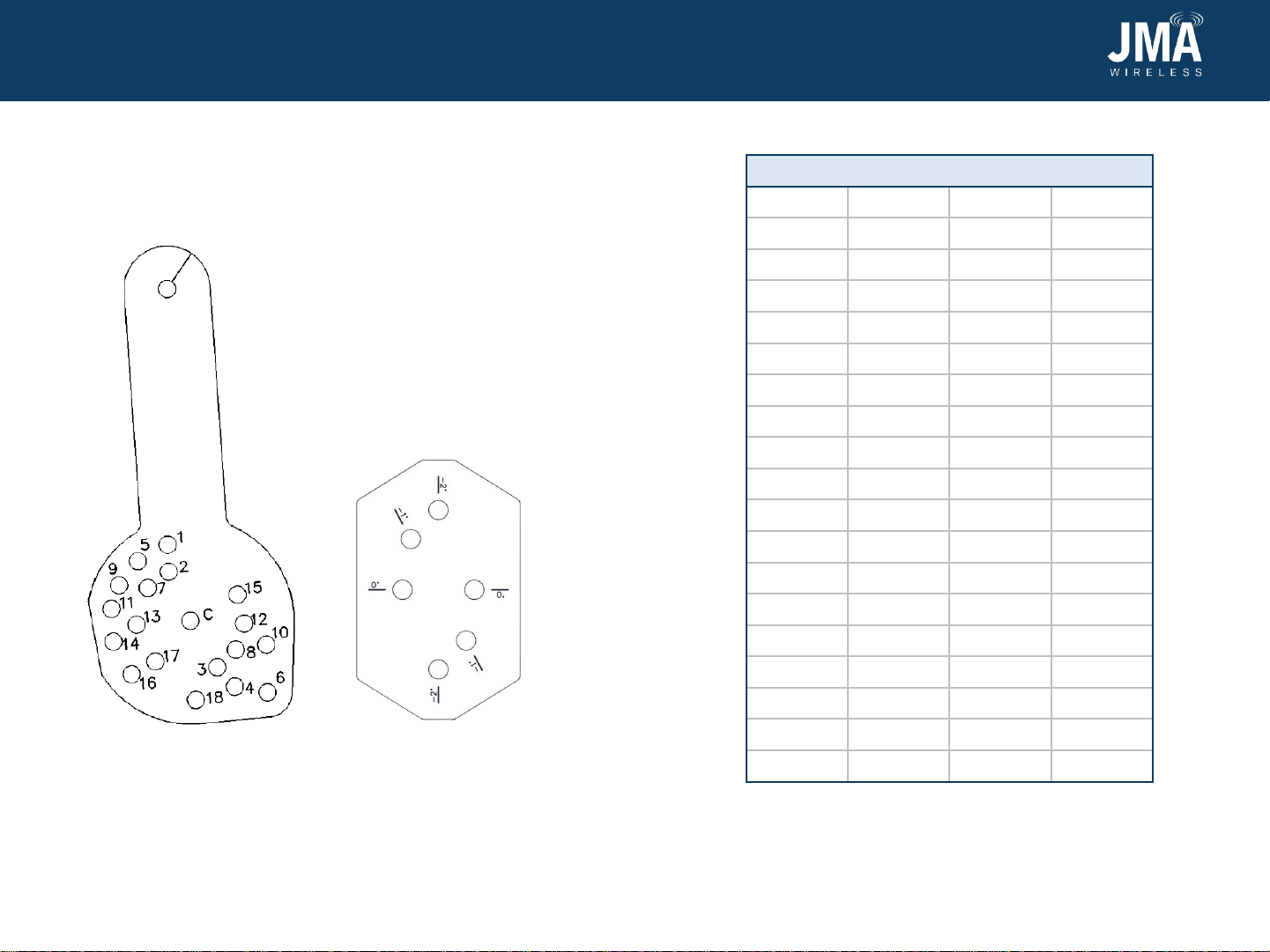
9. If a tilt other than 0 degrees is desired, reposition the antenna
according to the hole numbering on tilt select arm 10, Figure 5,
and downtilt Table 2. For bottom bracket 8, Figure 6, use 0 degrees
for downtilt, and -1 or -2 degrees for uptilt. Then tighten all
fasteners to 20 lb·ft.
Figure 5: Tilt select arm
Downtilt table (degrees)
Pin hole 4’ 6’ 8’
10 0 0
21.3 0.9 1
32.3 1.6 1.8
43.0 2.0 2.3
54.2 2.9 3.2
65.1 3.5 3.9
76.0 4.1 4.6
86.8 4.6 5.2
97.7 5.2 5.9
10 9.0 6.1 6.9
11 10.3 7.0 7.8
12 11.0 7.5 8.4
13 11.9 8.1 9.1
14 13.2 9.0 10.1
15 14.6 9.9 11.1
16 15.8 10.7 12.0
17 16.3 11.0 No use
18 17.8 12.0 No use
Table 2: Table for adjusting tilt
9
Figure 6: Bottom bracket
This manual suits for next models
3
Other JMA Wireless Antenna manuals


Popular Antenna manuals by other brands

Alfa Network
Alfa Network APA-L01 Specifications

Naval
Naval PR-422CA Operation manual

Feig Electronic
Feig Electronic ID ISC.ANTH200/200 Series manual

TERK Technologies
TERK Technologies TV44 owner's manual

Directive Systems & Engineering
Directive Systems & Engineering DSE2324LYRMK quick start guide

HP
HP J8999A instructions


CommScope
CommScope CMAX-OMFX-43M-I53 Installation instruction

Ramsey Electronics
Ramsey Electronics DAP25 Kit assembly and instruction manual

COBHAM
COBHAM SAILOR 800 VSAT Replacement procedure

Trango Systems
Trango Systems AD900-9 Specification sheet

Steren
Steren ANT-100 user manual

Proxim
Proxim 5054-PA-23 quick start guide