JMA Wireless 91900324 User manual

81900511 Rev. B
©2019 JMA Wireless. All rights reserved. This document contains proprietary information. All products, company names, brands, and logos are trademarks™ or
registered® trademarks of their respective holders. All specificationsare subject to change without notice.Revised: July 8, 2019
Installation Guide
Stadium
Mounting
Bracket Kit -
Rotational
JMA Wireless World
Headquarters
7645 Henry Clay Boulevard
Liverpool, NY 13088
USA
www.jmawireless.com
+1 888-201-6073
Instructions for Mounting Kits
91900324 & 91900325
P/N 81900511
22
Rev. Description ECO number
ARelease
BUpdated the installation
kits to add SX antenna
views and instructions for
91900313 and 9190055
bracket kits
75289 ECR00708
91900324: DX/SX Antenna
Mounting Bracket Kit (included in
antenna)
91900325: Replacement bracket kit
(sold separately)
919055: Optional bracket kit (sold
separately). Refer to P/N 81900510
for instructions
91900313: Optional bracket kit
(sold separately). Only for SX230
model, to be used with kits
91900324 & 91900325.

81900511 Rev. B
©2019 JMA Wireless. All rights reserved. This document contains proprietary information. All products, company names, brands, and logos are trademarks™ or
registered® trademarks of their respective holders. All specificationsare subject to change without notice.Revised: July 8, 2019
Installation Guide
Stadium Mounting Bracket -Rotational
Instructions for Mounting Kit 91900324
This is the installation guide for the Stadium Mounting Bracket -
Rotational. Note that bracket 45700440-01 comes pre-installed
on the antenna.
Antenna DX10FRO260-00/06 pictured for reference.
2 3
Figure 1: Bracket installed on DX antenna Figure 2: Bracket installed on SX antenna
The bracket can be repositioned depending upon use in the field.
When mounting the antenna, always follow the arrows and the word
“top” for correct placement. When the bracket is in horizontal mount, the
word “top” marked on the bracket will match the top of the antenna. But
in vertical mount, the bracket can be turned either way. Torque 1/4” SS
hardware to 75 lbf∙in (8.47 N∙m).
Antenna SX08FRO230-01 pictured for reference.

81900511 Rev. B
©2019 JMA Wireless. All rights reserved. This document contains proprietary information. All products, company names, brands, and logos are trademarks™ or
registered® trademarks of their respective holders. All specificationsare subject to change without notice.Revised: July 8, 2019
Installation Guide
Stadium Mounting Bracket -Rotational
Instructions for Mounting Kit 91900324
4 5
Figure 3: 91900324 kit
Kit #91900324
Item
#JMA part # Description Qty.
in kit
1457217-PF Center Mount Stadium
Bracket 1
2457216-PF Wall / Pipe Mount Stadium
Bracket 1
3413-011-2421-VS 3/8” FLAT WASHER SS
(OD 13/16) 4
4411-144-1348-VS 3/8”-16 x 1.000” HEX HEAD
BOLT FULL THRE 4
5413-012-2489-VS 3/8 SPLIT LOCK WASHER SS 4
6411-144-0732-VS 10-32 x 1/2” HEX Head Bolt
SS 2
7413-012-6789-VS #10 SPLIT LOCK WASHER
SS 2
8413-011-8518-VS #10 FLAT WASHER SS 2
981900511 Assembly instructions 1
Below is the bracket kit included with the antenna.

81900511 Rev. B
©2019 JMA Wireless. All rights reserved. This document contains proprietary information. All products, company names, brands, and logos are trademarks™ or
registered® trademarks of their respective holders. All specificationsare subject to change without notice.Revised: July 8, 2019
Installation Guide
Stadium Mounting Bracket -Rotational
Instructions for Mounting Kit 91900324
67
Venue bracket details (Figure 4):
Bracket 1 can be re-oriented 90°to support vertical mounting
configurations. Keep the word “top” on the antenna facing top, and the
weep hole facing down. Use Screw 6 for locking bracket into specific
angle positions. Torque to 30 lbf∙in (3.39 N∙m). Use the holes in Bracket
2 (4.50” [114.3 mm] apart @ CL) and 3/8” hardware for wall mounts.
Figure 4: Bracket kit details
Note:
•Parts 2-10 can be rotated 90°if needed, to rotate the antenna. For
example, Bracket 1 has two mounting positions on pre-installed
Bracket 45700440-01.
•When rotating the antenna, additional weep holes must be drilled
to properly drain antenna. Refer to JMA weep hole modification
guide at jmawireless.com
Other key details:
The brackets were designed to handle pole diameters ranging from
2.5 to 4.5 inches.
All 10-32 hardware to be torqued to 30 lbf∙in (3.39 N∙m).
All 3/8” hardware to be torqued to 20 lbf∙ft (27.12 N∙m).
All 1/4” hardware to be torqued to 75 lbf∙in (8.47 N∙m).
Fasteners / hose clamps for wall mount and pole mount not
included in 91900324 bracket kit. (Sold separately)

81900511 Rev. B
©2019 JMA Wireless. All rights reserved. This document contains proprietary information. All products, company names, brands, and logos are trademarks™ or
registered® trademarks of their respective holders. All specificationsare subject to change without notice.Revised: July 8, 2019
Installation Guide
Stadium Mounting Bracket -Rotational
Instructions for Mounting Kit 91900324
Wall-mounted bracket Pole-mounted bracket
See Figure 3, the bracket drawing, for the hole layout dimensions. All
3/8” hardware to be torqued to 20 lbf∙ft (27.12 N∙m).
8 9
Figure 5: DX model wall mount and pole mount Figure 6: SX model wall mount and pole mount
Plan view
Bracket attaches to wall using
appropriate 3/8” fasteners suitable
for wall structure (2 places each)
Torque to 20 lbf∙ft (27.12 N∙m)
Side view
Plan view
Side view
Bracket attaches to pole using
appropriate pole straps (4 places
each) Bracket attaches to wall using
appropriate 3/8” fasteners suitable
for wall structure (2 places each)
Torque to 20 lbf∙ft (27.12 N∙m)
Wall-mounted bracket Pole-mounted bracket
See Figure 3, the bracket drawing, for the hole layout dimensions. All
3/8” hardware to be torqued to 20 lbf∙ft (27.12 N∙m).
Bracket attaches to pole using
appropriate pole straps (4 places
each)

81900511 Rev. B
©2019 JMA Wireless. All rights reserved. This document contains proprietary information. All products, company names, brands, and logos are trademarks™ or
registered® trademarks of their respective holders. All specificationsare subject to change without notice.Revised: July 8, 2019
Installation Guide
Stadium Mounting Bracket -Rotational
Instructions for Mounting Kit 91900324
Vertical and horizontal mounting positions tables
Azimuth rotation for specific locking position. Use supplied #10-32
fasteners to lock bracket at specific angle.
Figure 7: Bracket azimuth rotation in vertical position
Mechanical downtilt rotation for specific locking position. Use supplied
#10-32 fasteners to lock bracket at specific angle.
10 11
Figure 8: Bracket mechanical downtilt rotation in horizontal
position
+ve side
-ve side
“-” indicates
negative angle
-ve side
+ve side
“-” indicates
negative angle
Azimuth Rotation Table: Max angle (degrees) pole/wall mount
Legend Azimuth
Rotation
(Deg)
Antenna (L) x (W)
1’x1’ 1’x2’ 1’x3’ 2’x2’
A 0
B 5
C10
D15
E20
F25
G30
H35
Angle
“X”
Angle
“X”
Mech. Downtilt Table: Max angle (degrees) pole/wall mount
Legend Azimuth
Rotation
(Deg)
Antenna (L) x (W)
1’x1’ 1’x2’ 1’x3’ 2’x2’
A 0
B 5
C10
D15
E20
F25
G30
H35
I40
J45
K50
Angle
“Y”
Angle
“Y”
X –X tilt Y –Y tilt
(L)
(W)

81900511 Rev. B
©2019 JMA Wireless. All rights reserved. This document contains proprietary information. All products, company names, brands, and logos are trademarks™ or
registered® trademarks of their respective holders. All specificationsare subject to change without notice.Revised: July 8, 2019
Installation Guide
Stadium Mounting Bracket -Rotational
Instructions for Mounting Kit 91900324
12 13
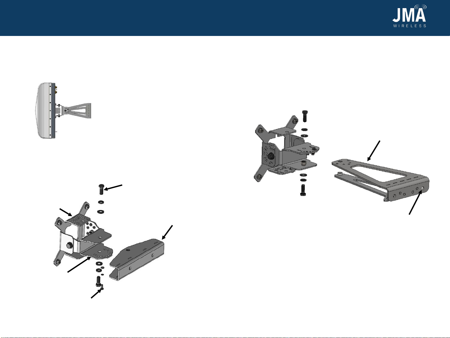
Replacement bracket kit (91900325).
Kit 91900325 (Figure 9) is sold separately and can be used instead of
919050. Kit 91900325 is identical to 91900324-01, except 45700440-01
is included in this kit; consequently, some extra hardware is provided,
i.e., 10 , 11 , and 12 .
Kit #91900325
Item
#JMA part # Description Qty.
in kit
145700440-01 Antenna Mount Stadium
Bracket 1
2457217-PF Center Mount Stadium
Bracket 1
3457216-PF Wall/Pipe Mount Stadium
Bracket 1
4413-011-2421-VS 3/8” FLAT WASHER SS
(OD 13/16) 4
5411-144-1348-VS 3/8”-16 x 1.000” HEX HEAD
BOLT FULL THRE 4
6413-012-2489-VS 3/8 SPLIT LOCK WASHER SS 4
7411-144-0732-VS 10-32 x 1/2” HEX Head Bolt
SS 2
8413-012-6789-VS #10 SPLIT LOCK WASHER SS 2
9413-011-8518-VS #10 FLAT WASHER SS 2
10 412-105-0907-VS NUT, HEX, 1/4-20,UNC,SS 4
11 413-011-1699-VS FLAT WASHER, 1/4
STAINLESS STEEL 4
12 413-012-1659-VS WASHER, LOCK, 1/4,SS 4
13 81900511 Assembly instructions 1
Figure 9: 91900325 bracket details

81900511 Rev. B
©2019 JMA Wireless. All rights reserved. This document contains proprietary information. All products, company names, brands, and logos are trademarks™ or
registered® trademarks of their respective holders. All specificationsare subject to change without notice.Revised: July 8, 2019
Installation Guide
Stadium Mounting Bracket -Rotational
Instructions for Mounting Kit 91900324
14 15
Below is the optional extension bracket kit 91900313
for inverted mount of larger antennas.
Figure 10 shows antenna SX08FRO230-01 (for reference only) pictured
after being fitted with extension bracket kit 91900313.
Figure 10: Inverted mount
Figure 12: Connecting the extension bracket to the antenna
mount stadium bracket
Extension kit
91900313
Antenna mount
stadium bracket
3/8”-16 hardware,
4 PL as shown
Center mount
stadium bracket
#10-32 screw, 2 PL (for
locking bracket into
specific angle position
Wall/pipe mount
stadium bracket
Step 1: Removing the wall/pipe mount bracket from the antenna
mount stadium bracket. Do not throw away any hardware. Remove 2
sets of 3/8”-16 hardware and the #10-32 screw from the connection of
the center mount stadium bracket and wall/pipe mount stadium bracket.
Remove the wall/pipe mount bracket from the assembly.
Step 2: Installing the extension bracket. Install extension bracket
kit 91900313 by securing the extension bracket to the center mount
stadium bracket using 3/8” hardware and #10-32 screw from Step 1. All
3/8” hardware to be torqued to 20 lbf∙ft. See pages 16-17 for horizontal
and vertical mounting positions tables.
Figure 11: Removing the
wall/pipe mount bracket
Wall mount holes,
2 PL, using 3/8”
hardware, 4.50”
apart @ centerline

81900511 Rev. B
©2019 JMA Wireless. All rights reserved. This document contains proprietary information. All products, company names, brands, and logos are trademarks™ or
registered® trademarks of their respective holders. All specificationsare subject to change without notice.Revised: July 8, 2019
Installation Guide
Stadium Mounting Bracket -Rotational
Instructions for Mounting Kit 91900324
16 17
Vertical and horizontal mounting positions tables
Azimuth rotation for specific locking position. Use supplied #10-32
fasteners to lock bracket at specific angles, at 5-degree increments, (+)
& (-) sides.
Mechanical downtilt rotation for specific locking position. Use supplied
#10-32 fasteners to lock bracket at specific angle.
“-” indicates
negative angle
Figure 13: Bracket azimuth rotation in vertical position
Figure 14: Bracket mechanical
downtilt rotation in horizontal
position
+ve side
-ve side
AZIMUTH ROTATION TABLE
LEGEND AZIMUTH
ROTATION (DEG)
A 0
B 5
C10
D15
E20
F25
G30
MECH. DOWNTILT TABLE
LEGEND DOWNTILT
ROTATION (DEG)
A 0
B 5
C10
D15
E20
F25
G30
H35
I40
J45
K50
L55
-ve side
+ve side

81900511 Rev. B
©2019 JMA Wireless. All rights reserved. This document contains proprietary information. All products, company names, brands, and logos are trademarks™ or
registered® trademarks of their respective holders. All specificationsare subject to change without notice.Revised: July 8, 2019
Installation Guide
Stadium Mounting Bracket -Rotational
Instructions for Mounting Kit 91900324
18 19
Below is the optional extension bracket kit 91900313 for
inverted mount of larger antennas.
Figures 15 and 16 show kits 91900324, 91900313, and 919055 together.
SX model antenna pictured for reference.
Figure 15: Inverted mount
Figure 16: Inverted mount: side view details
Band straps
(2 places)
(not included
in kit)
Inverted mount bracket kit
P/N 919055
Extension bracket kit
P/N 91900313
3/8”
hardware
torque:
20 lbf∙ft
(27.12 N∙m)
* Approximate
dimensions
Pre-installed
venue bracket kit
91900324
This hardware is included in kit 919055.
For more information, refer to Venue
Bracket Installation Guide 81900510.

81900511 Rev. B
©2019 JMA Wireless. All rights reserved. This document contains proprietary information. All products, company names, brands, and logos are trademarks™ or
registered® trademarks of their respective holders. All specificationsare subject to change without notice.Revised: July 8, 2019
Installation Guide
Stadium Mounting Bracket -Rotational
Instructions for Mounting Kit 91900324
20 21
Below is the optional bracket kit 919055 for inverted
mount.
Figures 17 and 18 show both kits 91900324 and 919055 together. DX
model antenna pictured for reference.
Figure 17: Inverted mount
Figure 18: Inverted mount: side view details
Band straps
(2 places)
(not included
in kit)
Inverted mount bracket kit
P/N 919055
Pre-installed
venue bracket kit
91900324
3/8” hardware torque:
20 lbf∙ft (27.12 N∙m).
* Approximate dimensions
This hardware included in kit 919055.
For more information, refer to Venue
Bracket Installation Guide 81900510.
This manual suits for next models
1
Table of contents