JMA MX User manual

81900507 Rev. 05
©2023 JMA Wireless. All rights reserved. This document contains proprietary information. All products, company names, brands, and logos are trademarks™or
registered® trademarks of their respective holders. All specifications aresubject to change without notice.Revised: August 17, 2023
+1 315.431.7100 customerservice@jmawireless.com
Installation Guide
MX/MC
Model
Bracket
JMA Wireless World
Headquarters
140 Cortland Avenue
Syracuse, NY 13202
USA
www.jmawireless.com
+1 888-201-6073
Instructions for Four-, Six-,
and Eight-FootAntennas
P/N 81900507
10
Rev. Description EC number
01 Initial release
02 Format change 73380
03 Kit #91900319 BOM update 77194
04 Updated JMA Logo ECO-00263
ECR02515
05 Updated HQ address ECO-00407
ECR02611
*8’ configuration shown
81900507 Rev. 05
©2023 JMA Wireless. All rights reserved. This document contains proprietary information. All products, company names, brands, and logos are trademarks™or
registered® trademarks of their respective holders. All specifications aresubject to change without notice.Revised: August 17, 2023
+1 315.431.7100 customerservice@jmawireless.com
Installation Guide
MX/MC Model Brackets
Instructions for Four-, Six-, and Eight-Foot Antennas
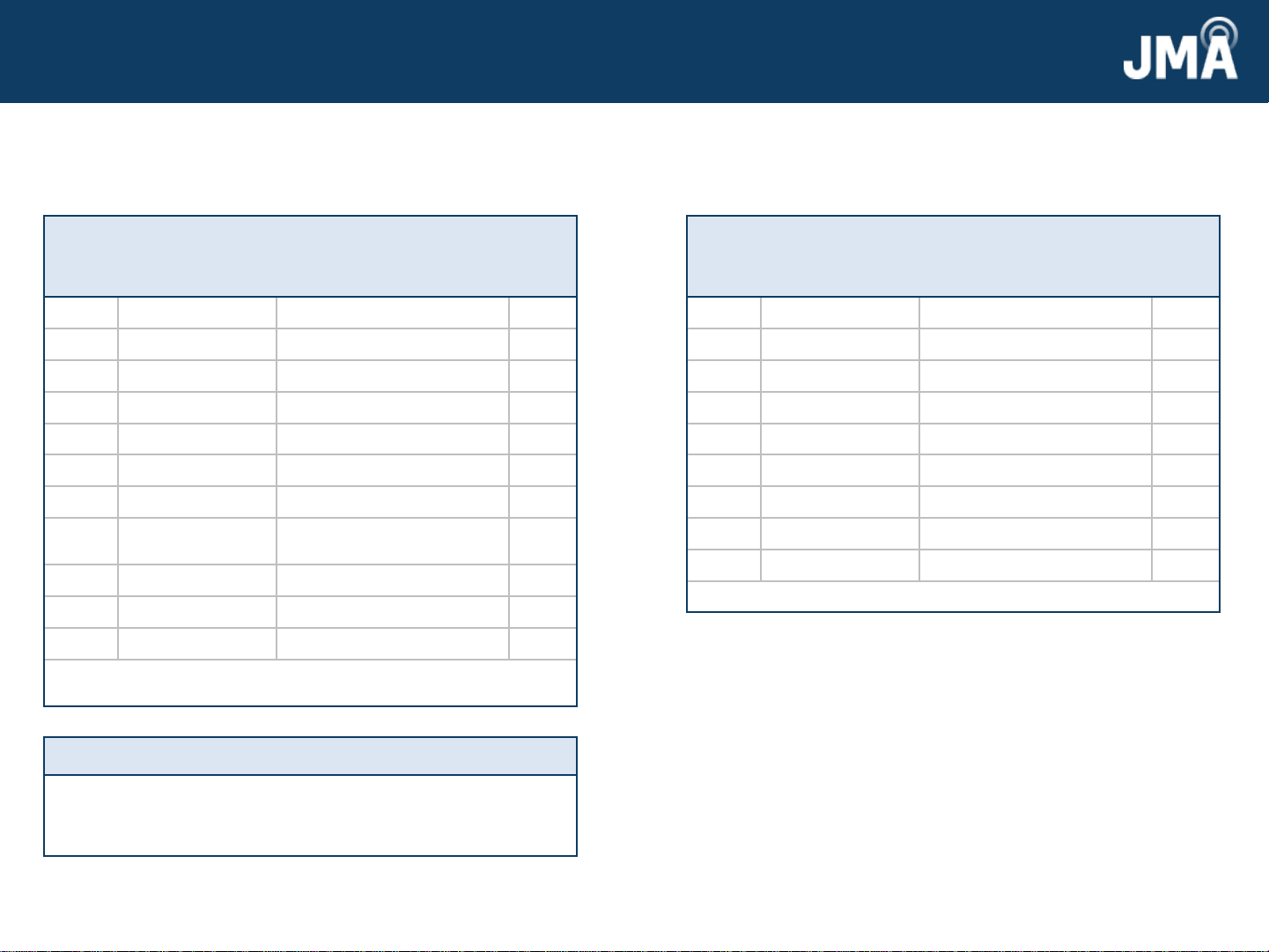
Kit #91900318: 4-, 6-, & 8-foot antennas
Item
#
Part # Description Qty.
in kit
145700384-01 Back grip bracket 2
245700385-01 Anti-rotation bracket 2
345700382-01 Single mount adapter 2
441100318-01 Threaded rod 4
5413-441-2721-VS 3/8” flat washer, HDG 38
6413-452-2721-VS 3/8” lock washer, HDG 21
7412-044-1323-VS 3/8” hex nut, galv. 25
845700391-01 Negative degree adj. bottom
bracket
2
9411-057-1352-VS 3/8” bolt, HDG 13
10 45700381-01 Tilt select arm 2
11 45700380-01 Antenna linkage arm 2
NOTE: These item numbers refer to Figures 1 and 2on pages 4
and 5.
Other key details:
▪The brackets were designed to handle pole diameters ranging from
2.5 to 4.5 inches.
▪When tightening all hardware, use the torque setting 20 lb·ft.
This is the installation guide for the MX/MC model
brackets. Below is the bracket kit included with the
antenna.
2 3
Kit #91900319: 8-foot antenna
Item
#
Part # Description Qty.
in kit
145700384-01 Back grip bracket 1
245700385-01 Anti-rotation bracket 1
345700382-01 Single mount adapter 1
441100318-01 Threaded rod 2
5413-441-2721-VS 3/8” flat washer, HDG 18
6413-452-2721-VS 3/8” lock washer, HDG 10
7412-044-1323-VS 3/8” hex nut, galv. 12
9411-057-1352-VS 3/8” bolt, HDG 6
12 45700389-01 Center link bracket 4
NOTE: These item numbers refer to Figure 3 on page 6.
Additional kit included with the 8-foot antenna.
81900507 Rev. 05
©2023 JMA Wireless. All rights reserved. This document contains proprietary information. All products, company names, brands, and logos are trademarks™or
registered® trademarks of their respective holders. All specifications aresubject to change without notice.Revised: August 17, 2023
+1 315.431.7100 customerservice@jmawireless.com
Installation Guide
MX/MC Model Brackets
Instructions for Four-, Six-, and Eight-Foot Antennas
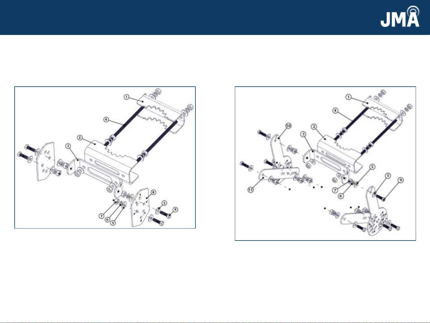
Attach bottom bracket to antenna
1. Install bottom mount pieces—back grip bracket 1, anti-rotation
bracket 2, single mount adapter 3, and bottom bracket 8—onto
antenna as shown in Figure 1 using threaded rods 4 and the
following 3/8” hardware: 5, 6, 7, and 9.
4 5
Figure 1: Bottom mount
2. Connect the single mount adapter 3 and bottom bracket 8 using the
hole labelled “0.” If you need to do a -1oor -2otilt, use the labeled
holes on the bottom bracket plate. Leave the fasteners associated
with tilt and pole loose enough to allow free rotation of the parts.
Make sure the threaded rods do not extend past the nut closest to
the antenna.
Figure 2: Top mount
Attach top bracket to antenna
3. Install top mount pieces—back grip bracket 1, anti-rotation bracket
2, single mount adapter 3, antenna linkage arm 11, and tilt select
arm 10 onto antenna as shown in Figure 2 using threaded rods 4
and the following 3/8” hardware: 5, 6, 7, and 9.
4. Fasten antenna linkage arm 11 and tilt select arm 10 together using
holes “C” and “1” for default tilt. Leave all fasteners associated with
tilt and pole loose enough to allow free rotation of the parts. Make
sure the threaded rods do not extend past the nut closest to the
antenna.

81900507 Rev. 05
©2023 JMA Wireless. All rights reserved. This document contains proprietary information. All products, company names, brands, and logos are trademarks™or
registered® trademarks of their respective holders. All specifications are subject to changewithout notice. Revised: August 17, 2023
+1 315.431.7100 customerservice@jmawireless.com
Installation Guide
MX/MC Model Brackets
Instructions for Four-, Six-, and Eight-Foot Antennas
Extended step for 8-foot antenna installation
5. Install center mount pieces—back grip bracket 1, anti-rotation
bracket 2, and center link bracket 12—onto antenna as shown in
Figure 3 using threaded rods 4 and the following 3/8” hardware: 5,
6, 7, and 9. Leave all fasteners associated with tilt and pole loose
enough to allow free rotation of the parts. Make sure the threaded
rods do not extend past the nut closest to the antenna.
Figure 3: Center mount (8-foot antenna)
Mounting antenna to pole
6. Attach the antenna to the pole by placing the anti-rotation bracket
2 against the pole and sliding back grip 1 onto the back of the pole.
Repeat attachment for each mount bracket. See Figures 1, 2, and
3.
7. Use measurements from Table 1 and Figure 4 to determine the
distances between brackets.
8. Tighten all nuts on the threaded rods to 20 lb·ft.
6 7
Figure 4: Bracket
heights for MX/MC
A B C
8’
antennas 20.5” 30.0” N/A
6’
antennas N/A N/A 63.75”
4’
antennas N/A N/A 42.75”
Table 1: Bracket
height key

81900507 Rev. 05
©2023 JMA Wireless. All rights reserved. This document contains proprietary information. All products, company names, brands, and logos are trademarks™or
registered® trademarks of their respective holders. All specifications are subject to changewithout notice. Revised: August 17, 2023
+1 315.431.7100 customerservice@jmawireless.com
Installation Guide
MX/MC Model Brackets
Instructions for Four-, Six-, and Eight-Foot Antennas
8
9. If a tilt other than 0 degrees is desired, reposition the antenna
according to the hole numbering on tilt select arm 10, Figure 5,
and downtilt Table 2. For bottom bracket 8, Figure 6, use 0 degrees
for downtilt, and -1 or -2 degrees for uptilt. Then tighten all
fasteners to 20 lb·ft.
Figure 5: Tilt select arm
Downtilt table (degrees)
Pin hole 4’ 6’ 8’
10 0 0
21.3 0.9 1
32.3 1.6 1.8
43.0 2.0 2.3
54.2 2.9 3.2
65.1 3.5 3.9
76.0 4.1 4.6
86.8 4.6 5.2
97.7 5.2 5.9
10 9.0 6.1 6.9
11 10.3 7.0 7.8
12 11.0 7.5 8.4
13 11.9 8.1 9.1
14 13.2 9.0 10.1
15 14.6 9.9 11.1
16 15.8 10.7 12.0
17 16.3 11.0 No use
18 17.8 12.0 No use
Table 2: Table for adjusting tilt
9
Figure 6: Bottom bracket
This manual suits for next models
3


