JMR electronics 1005 User manual

HYDRAULIC/PNEUMATIC BENDER
P/N 1005
WARNING
Read and understand all warnings, instructions and manual information
before attempting to use this equipment.
1. Because of the precision air return NEVER store or leave the cylinder in the
full extended/open position. If left in the extended position the hydraulic
fluid will drain from the cylinder. When the air supply is reattached the
cylinder could retract uncontrollably and could cause equipment damage
and/or sever personal injuries. Use extreme care when reattaching the air
supply to the bender. Make sure there are no dies, pins, body parts on the
bender when reattaching the air source to the pump.
2. User assumes all risks when using this product.
3. Always pay close attention to what you are doing. Turn off cell phone,
pager, etc when using this machine.
4. This machine is meant to be operated by competent individuals who have a
thorough understanding of tube bending and machines in general.
5. The bender is intended to be used by a single operator. Never allow a
second individual to operate the machine while another holds tube.
6. Always wear eye protection while operating tube bender.
7. Never put your hands or other body parts into bender apparatus.
8. Never wear loose clothing while operating tube bender.

9. Always work in a clean, safe, well lit, level work area.
10. Never use the wrong size die/type die for the tube being worked.
11. Never operate the tube bender with broken, worn or damaged parts.
12. DO NOT attempt to repair and reuse any damaged bender parts.
13. DO NOT attempt to repair and reuse any damaged AIR HYDRAULIC
PUMP parts.
14. Use the AIR HYDRAULIC PUMP in the upright position only.
15. Hold the foot valve down ONLY until you hear pump stop pumping after
the full stroke is attained.
16. Alteration of these products is strictly prohibited.
17. Use only those adapters and attachments provided and approved by the
manufacturer.
18. Always inspect hoses and connections for damage prior to use.
MOUNTING THE BENDER
1. JMR offers a floor mount specifically designed for the MS1005
HYDRAULIC/PNEUMATIC BENDER.
2. If you are fabricating your own permanent mounting for the bender, ie: to a
workbench, make sure it is stable and securely mounted to the floor.
3. If you are fabricating your own portable mounting for the bender, make sure the
base is large enough to be stable when bending long pieces of material.
4. See Figure 1 for mounting dimensions.
BLEEDING THE HYDRAULIC SYSTEM
WARNING
Never put your hands or other body parts into bender apparatus.
1. Use only a high quality hydraulic oil to fill the hydraulic pump. DO NOT use
any other type of oil in the bender, i.e.: motor oil, transmission fluid, etc.
2. Connect the foot control to an air supply, not to exceed 90psi as shown in Figure
1.
3. Using the foot control valve (heel down to extend and toe down to retract), cycle
the bender cylinder several times and check that the level of hydraulic oil is
between ½” and 1” from the fill plug. Add hydraulic oil if necessary. See Figure
1.

4. Be sure to check the level of the hydraulic oil frequently. DO NOT allow the
reservoir to run dry. This will void the warranty.
5. Under normal use, the pivot bushings should be greased every 250-500 cycles.
Under high use conditions it will be necessary to grease the pivot bushings every
month or more often as necessary.
6. Inspect and replace bushing when worn or sloppy.
WARNING
DO NOT attempt use damaged parts in the tubing bender.
For your safety, DO NOT attempt to repair and reuse any damaged bender
parts.
7. Replace any worn, bent, or damaged parts immediately. Replacement parts are
available from JMR Manufacturing or your local dealer.
8. Replace any worn or damaged hydraulics hoses immediately. Replacement hoses
are available from JMR Manufacturing or your local dealer.
9. Replace any worn or damaged Air Hydraulics Pump parts immediately using
only factory authorized parts. Parts are available from JMR Manufacturing or
your local dealer.
10. Dies are available for tubing (measured by outside diameter), or Sched 40 pipe.
Always use the proper size/type of die for the material being worked.
OPERATION OF THE BENDER
WARNING
Because of the precision air return NEVER store or leave the cylinder in the
full extended/open position. If left in the extended position the hydraulic fluid
will drain from the cylinder. When the air supply is reattached the cylinder
could retract uncontrollably and could cause equipment damage and/or sever
personal injuries. Use extreme care when reattaching the air supply to the
bender. Make sure there are no dies, pins, body parts on the bender when
reattaching the air source to the pump.
1. Connect the foot control valve to an air supply, not to exceed 90lbs as shown
in Figure 1.
2. The tubing material should be clean and free from defects.
3. Always grease the die block prior to bending.
4. Make sure that all drive pins are fully seated.
5. Pass tube into die and position as required for start of bend. All bends will
start at the edge of the radius die as shown in Figure 2.
6. Install the U strap and snug retainer bolt if needed.
WARNING
Never put your hands or other body parts into bender apparatus.

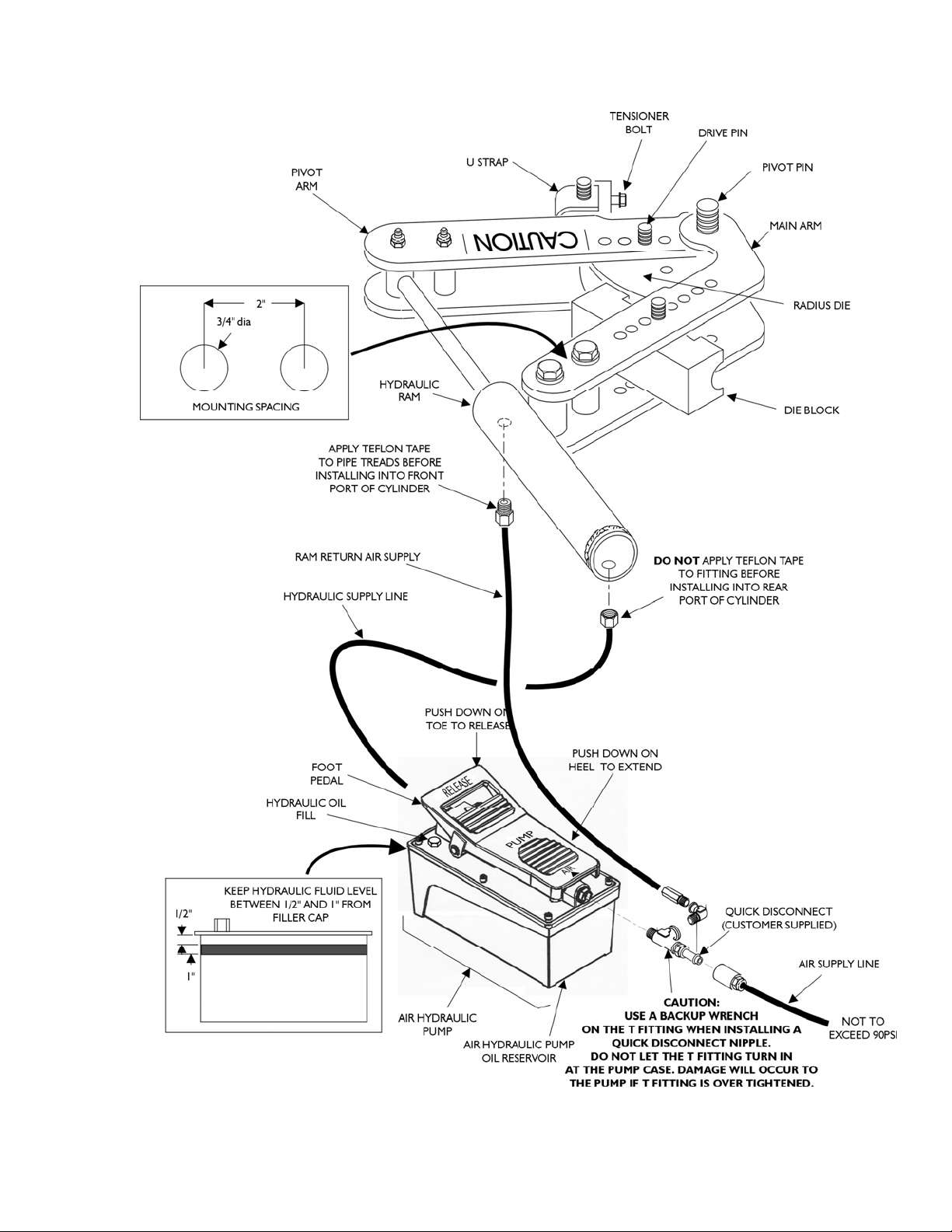
7. Using the foot control valve, extend the ram (down on the heel portion of the
foot valve. See Figure 1.) to the full stroke (or as needed for shorter bends).
WARNING
DO NOT hold the foot valve down any more than a few seconds after the full
stroke is attained. Serious injury and/or equipment damage may occur if foot
valve is held open and excess pressure is allowed to build up in the hydraulic
cylinder.
Burst hazard exists if hose or connection pressure exceeds rated pressure.
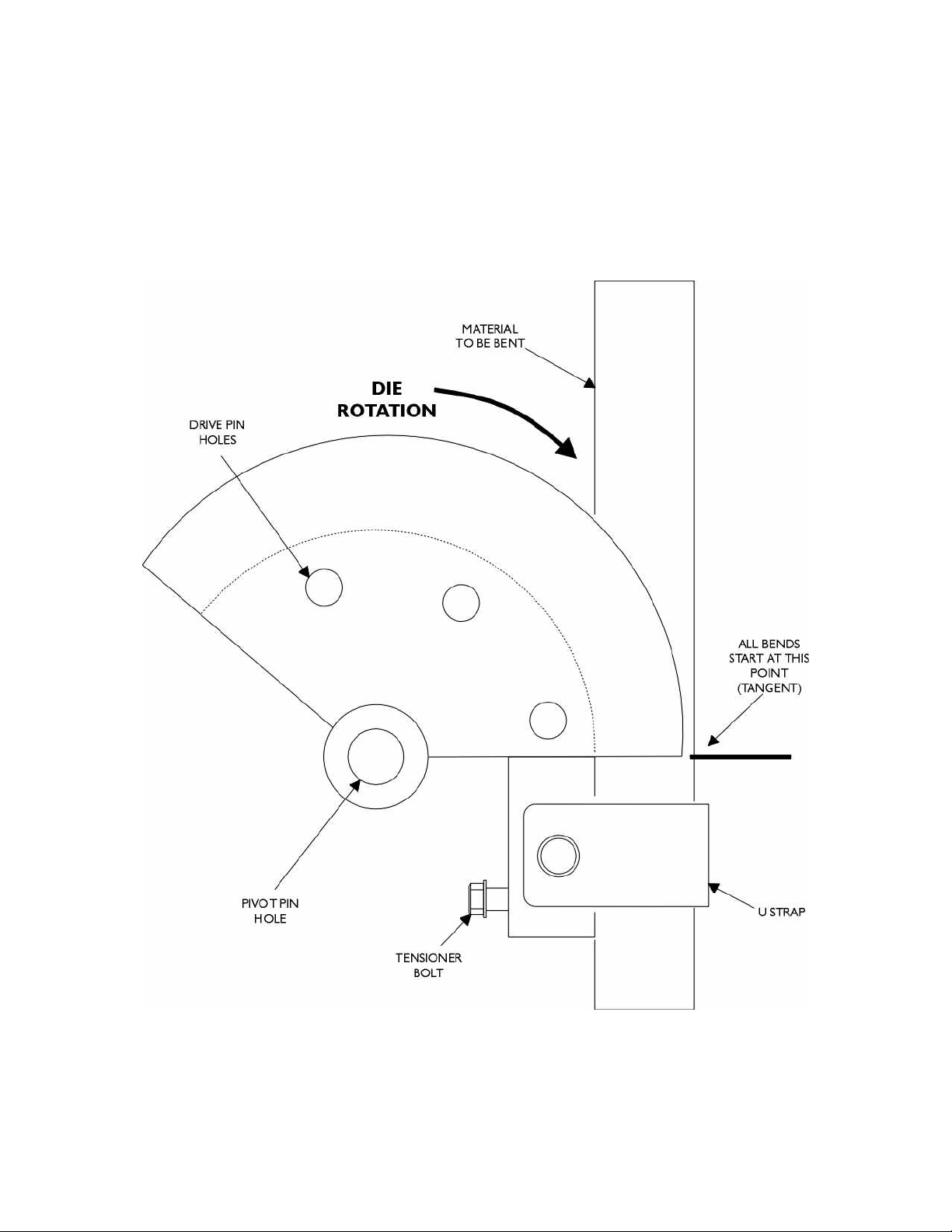
8. There is an approximate maximum 41º bend for each full stroke of the ram.
9. Pulling up on the drive pin, begin to slowly retract the ram (down on the toe
of the foot control valve) removing the pin when tension on the pin is released
and before it starts to rotate the die.
WARNING
In some cases when retracting the ram the tubing being bent could become
stuck in the radius die. Using great caution, pull sharply on the end of the
tubing to
release the tubing from the radius die.
10. Slowly retract the ram (down on the toe of the foot control valve) until the
second die drive hole lines up.
11. Re-install the pin fully and repeat the above bend process to complete the total
bend.
12. To repeat bends, without the degree wheel, measure ram's travel.
13. When the tube is bent the desired amount, slowly retract (down on the toe of
the foot control valve) the ram allowing the drive pin to rotate the die and
releasing the tube. It may be necessary to loosen the U-strap retaining bolt.
WARNING
Because of the precision air return NEVER store or leave the cylinder in the
full extended/open position. If left in the extended position the hydraulic fluid
will drain from the cylinder. When the air supply is reattached the cylinder
could retract uncontrollably and could cause equipment damage and/or sever
personal injuries. Use extreme care when reattaching the air supply to the
bender. Make sure there are no dies, pins, body parts on the bender when
reattaching the air source to the pump.
WARNING
In some cases when retracting the ram the tubing being bent could become
stuck in the radius die. Using great caution, pull sharply on the end of the
tubing to release the tubing from the radius die.
14. Remove the tube.
15. Use the smaller diameter drive pin (included) with any die that uses the first
drive hole (closest to the pivot point).

WARRANTY
1. One year limited warranty on tube bender.
2. Limited lifetime manufacturers warranty on the Air Hydraulic Pump.
3. Limited lifetime warranty on dies against breakage. Warranty is void if damaged
due to abuse or misuse.
4. Warranty item must be sent to JMR Manufacturing postage pre-paid for
inspection. JMR Manufacturing will replace or repair item at their discretion.
5. JMR Manufacturing makes every attempt to satisfy customers as quickly as
possible.
6. JMR Manufacturing will not accept any responsibility for personal injury or
property damage arising from the failure of any parts manufactured and/or sold
by JMR Manufacturing, LLC.


Figure 1. Bender overall view.
Figure 2. Bends start at edge of radius die.

Distributed by:
Trick-Tools
80 Truman Road
Pella, IA 50219
Phone:1-877-VAN-SANT
E-mail: sales@trick-tools.com
Here at Trick Tools we believe that our customers deserve the best
value in their tool and equipment purchases. We are constantly at
work searching out a variety of high quality, high performance tools
to oer at the best prices possible. Our commitment to you is that
we will not oer “cheap junk” anywhere on our website. You, the
customer, help us to evaluate our products constantly and as soon as
an ongoing quality issue is uncovered we will correct it or disconnue
that product immediately. We hope to earn your connued trust.
Table of contents