Johannus DSA-4 User manual

User’s Manual
JOHANNUSJOHANNUS
DigitalStereoAcousticsDSA-4

User’s Manual DigitalStereoAcousticsDSA-4
JOHANNUSJOHANNUS
Document information
Document Code DSA4V101US.wpd
Document Title User’s Manual JOHANNUS Digital Stereo Acoustics DSA-4
Issue Date October 1998
Serial Number
© Copyright 1998 JOHANNUS Orgelbouw b.v. The Netherlands
All rights reserved. No part of this publication may be reproduced and/or published by print, microfilm, audiotape,
electronically, mechanically or any other means, or stored in an information retrieval system, without prior written
permission from JOHANNUS Orgelbouw.
The information in this document is subject to change without notice and should not be considered a commitment
by Johannus Orgelbouw b.v. No responsibility is assumed for any error which may be appear in this document.

User’s Manual DigitalStereoAcousticsDSA-4
JOHANNUSJOHANNUS
Introduction
Congratulations on your decision to purchase a new JOHANNUS acoustic system.
With the 4-channel Digital stereo acoustics (DSA-4) you are able to create an acoustical environment
in your room, electronically, similar to that of a cathedral or a concert hall.

User’s Manual DigitalStereoAcousticsDSA-4
JOHANNUSJOHANNUS
Table of Contents
Installation ................................................................... 1
The acoustic system ...................................................... 1
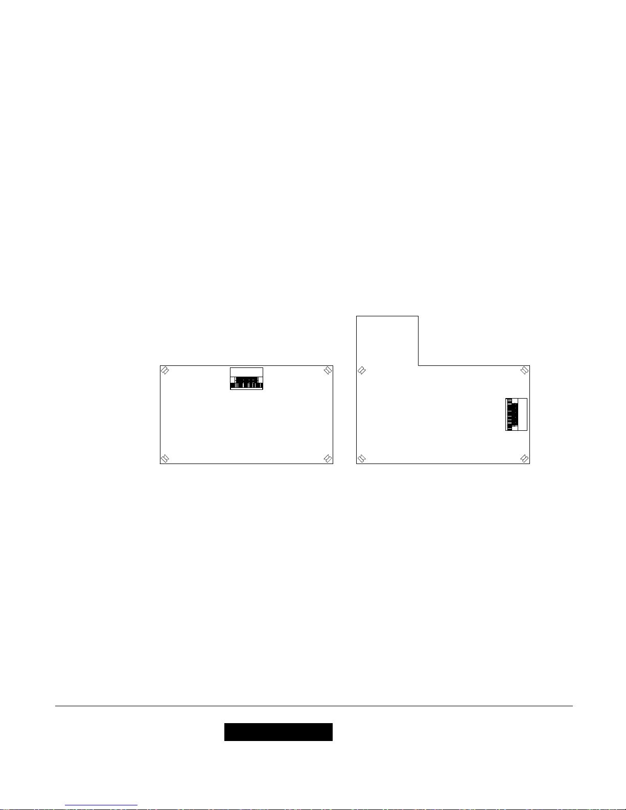
Installing the loudspeaker boxes ............................................. 1
Installing the acoustical .................................................... 1
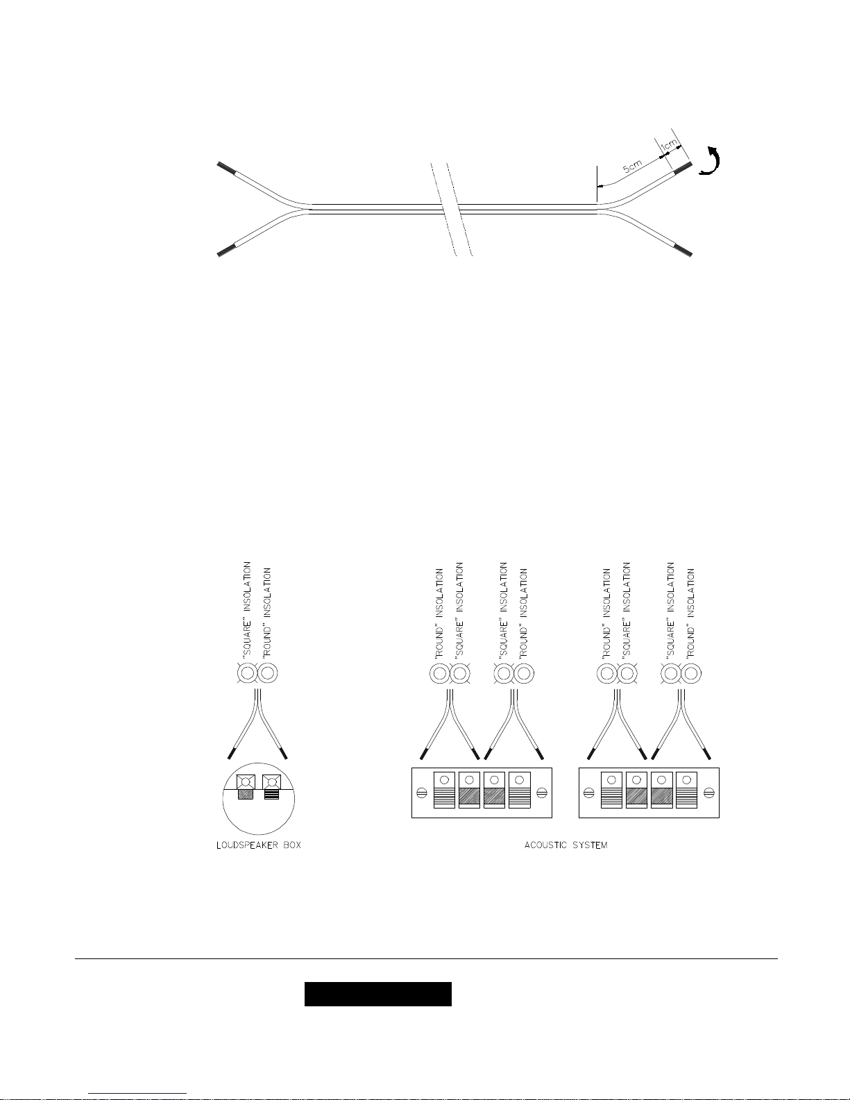
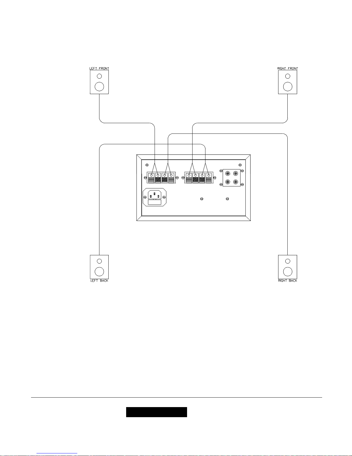
Connecting the loudspeaker boxes ........................................... 1
Connecting other devices .................................................. 4
Organ ........................................................... 4
Second device .................................................... 4
Set up ....................................................................... 5
Connecting the powercord .................................................. 5
Switching on ............................................................ 5
Controls .................................................................... 6
Frontpanel ............................................................. 6
Switch Organ/Aux In ...................................................... 7
LED indicator ........................................................... 7
Adjusting the input signal level .............................................. 7
Adjusting proportions direct signal/acoustic signal ................................ 7
Adjusting the output signal level ............................................. 8
Program switch ......................................................... 8
Program ............................................................... 9
Power switch ............................................................ 9
Maintenance ................................................................ 10
Guarantee .................................................................. 10
Apendices .................................................................. 11
Technical specifications .................................................. 11
acoustic system .................................................. 11
Loudspeaker boxes ............................................... 11

User’s Manual DigitalStereoAcousticsDSA-4
JOHANNUSJOHANNUS
1
Installation
The acoustic system
The complete system consists of:
!Acoustic system
!4 loudspeaker boxes
!1 powercord
!30 meter (90') loudspeaker cable
!1 audio cable
Installing the loudspeaker boxes
First of all you have to install the loudspeakers in their correct location. The best result is
obtained by installing the loudspeakers in a square as large as possible around the “listener’s
location”. Normally this is the place where you as the organist are playing the organ.
The drawings below give a possible loudspeaker configuration in a square and an L-shaped
room.
Installing the acoustical
Determine the correct placement for the acoustical system control console considering the
length of the loudspeaker cables. Typically this is on top of the organ left or right of the music
rack.
Connecting the loudspeaker boxes
Cut the supplied loudspeaker cable in 4 (different) lengths to connecting the four loudspeaker
boxes. Split-up each end of the 4 loudspeaker cables for about 5 cm (2") and strip each wire
1cm ( 0.5").

User’s Manual DigitalStereoAcousticsDSA-4
JOHANNUSJOHANNUS
2
Twist the stripped ends of each wire to make it easy to connect them to the connector of the
loudspeaker boxes (see drawing).
To connect the loudspeaker wires push the red or the black connector button at the back of the
loudspeaker box or the acoustical system. Put the end of the stripped wire into the connector
hole and release the red (black) connector button.
To avoid a bad connection you have to check if only the stripped wire end is put in the connector
hole. When the insulation is put in the connector hole too, this channel will not work.
Also check if the loudspeakers are not connected in anti-phase. This means that the polarity of
the two wires is not the otherway around compared to the other loudspeaker boxes. This results
in the fact that the loudspeakers will work against each other instead of working together to
reproduce the sound. This wrong connection will give no defects to the device or the speakers
though. To avoid this ani-phase connection you have to make sure to always connect the wire
with the ‘round’ insulation into the red connector button of the speaker box and the wire with the
‘square’ insulation into the black connector button of the speaker box (see drawing).

User’s Manual DigitalStereoAcousticsDSA-4
JOHANNUSJOHANNUS
3
To achieve the optimal sound spread of channels it is the best to set up the loudspeakers as in
the following drawing.

User’s Manual DigitalStereoAcousticsDSA-4
JOHANNUSJOHANNUS
4
Connecting other devices
After connecting the loudspeaker boxes you connect the organ and or possibly an other device
like, for example a Hifi system to the Johannus digital acoustic surround system.
For this purpose there are four audio inputs at the back of the acoustic device.
Organ
The two most right inputs (seen from the back) are the organ inputs for left and right.
Second device
The two left inputs (seen from the back) are the inputs for another device. These are the inputs
for left and right.

User’s Manual DigitalStereoAcousticsDSA-4
JOHANNUSJOHANNUS
5
Set up
Connecting the powercord
1. Check if the voltage as indicated on the serial number plate matches the main power voltage
the system will be connected to. The serial number plate is located at the back of the
acoustic device.
2. Connect the supplied power cord to the main power connection. Integrated in the main power
connection is the main fuse (see drawing).
3. Connect the acoustic system to a grounded outlet. If it is not grounded some functions may
not work apropriate.
Switching on
First switch on the connected devices like the organ and e.g. a Hifi-equipment. Then switch on
the acoustic device by pushing the power switch. The power switch indicator light will light up.

User’s Manual DigitalStereoAcousticsDSA-4
JOHANNUSJOHANNUS
6
Controls
Frontpanel
All controls are located at the front of the DSA-4. The control functions are indicated on the
drawing as follows:
1. Switch: Organ / Aux In (other device)
2. LED indicator
3. Input level control
4. Proportion control of direct sound / acoustic sound
5. Output level control
6. Program switch
7. Program adjustment
8. Power switch
These functions will be explained in the following pages.

User’s Manual DigitalStereoAcousticsDSA-4
JOHANNUSJOHANNUS
7
Switch Organ/Aux In
This switch allows you to switch to the device you want to add the acoustic surround sound to.
When the switch is not pushed-in the organ is connected to the acoustic system.
When the switch is pushed-in the second device that has been connected (e.g. a Hifi stereo
equipment) is connected to the acoustic system.
LED indicator
The LED indicates the level of the input signal.
The LED lights up in green with an average signal level.
The LED lights up in red when the signal level exceeds a certain level. This will cause so a
distorsion to occur.
Adjusting the input signal level
With the rotary control INPUT the input signal level can be adjusted.
This level must be adjusted so that the LED will light up in green only when a signal is received.
The rotary control will adjust both the right as well as the left input signal at the same time.
Adjusting proportions direct signal/acoustic signal
With the rotary control MIX you can balance the direct (dry) signal and the reverb (wet) signal
that will come from the acoustic system’s loudspeakers.
The direct signal is the received signal that is amplified and reproduced without adding a reverb.
The indirect signal is the received signal that has been processed into a reverb signal.
By turning the MIX rotary control to the left there will be more direct signal and less reverb signal
coming from the loudspeakers. When the MIX control is completely turned to the left only direct
signal wil be audible.
By turning the MIX rotary control to the right there will be more reverb signal and less direct
signal coming from the loudspeakers. When the MIX control is completely turned to the right
only reverb signal wil be audible.

User’s Manual DigitalStereoAcousticsDSA-4
JOHANNUSJOHANNUS
8
Adjusting the output signal level
With the rotary control OUTPUT you can adjust the volume of the output signal of the acoustic
system.This means the signal from the MIX control containing direct and reverb signal
depending on the adjustment of the MIX rotary control.
This control adjusts all four output channels at the same time.
Program switch
With the program switch you can make a choice of sixteen available acoustical programs.
Here follows a brief description of the sixteen programs.
1. Large concert hall with a bright response
2. Large concert hall with a mellow response
3. Mid-size concert hall
4. Mid-size studio
5. Small studio
6. Studio with a mellow response
7. Repeatative decaying reverb effect
8. Plate Reverb with a bright response
9. Plate Reverb with a mellow response
10. Plate Reverb
11. Slow tremolo effect
12. Deep chorus effect
13. Delayed signal effect
14. Chorus effect in a large room
15. Chorus effect in a large room including a delayed signal effect
16. Chorus effect as occurring in rotating speaker systems

User’s Manual DigitalStereoAcousticsDSA-4
JOHANNUSJOHANNUS
9
Program
With the rotary control ADJUST you can change one parameter of the program selected with
the switch. This will magnify or weaken the effect of the program you have chosen.
Here follows the adjustment you can make on the selected program.
Program 1. Reverb length
Program 2. Reverb length
Program 3. Reverb length
Program 4. Reverb length
Program 5. Reverb length
Program 6. Reverb length
Program 7. Effect of repetition
Program 8. Reverb length
Program 9. Reverb length
Program 10. Reverb length
Program 11. Tremolo depth
Program 12. chorus effect depth
Program 13. Delay time
Program 14. Reverb length
Program 15. Delay time
Program 16. Speed of rotation
Power switch
With the power switch you can switch the acoustic system on and off. When the acoustic system
is on the red light in the power switch will light up.
To avoid a ‘plop’ through the loudspeakers of the DSA-4 please first switch on the attached
devices, like an organ or other devices like a Hifi-equipment, before switching on the acoustic
system.

User’s Manual DigitalStereoAcousticsDSA-4
JOHANNUSJOHANNUS
10
Maintenance
The console consists of wooden veneer and solid wooden parts.
To clean the cabinet use a normal duster or a light wet cloth or chamois and polish with a dry
cloth.
We do not recommend furniture- or teak oil because it may be harmful for the lacquer.
Direct sunlight may change the color of the cabinet, especially light oak covers.
Guarantee
With the purchase of your DSA-4 you received a limited warrantee card. Please read the
conditions carefully and send the bottom part to JOHANNUS orgelbouw b.v. in Ede as soon as
possible. Again we want to emphasize that modifications on the DSA-4 or incompetent handling
will end the warrantee.

User’s Manual DigitalStereoAcousticsDSA-4
JOHANNUSJOHANNUS
11
Apendices
Technical specifications
acoustic system
Voltage ...................230V (110V)
Frequency .................50 Hz (60 Hz)
Max supplied power ..........120Watt
Max power per channel .......20Watt
Impedance per channel .......8Ù
Input impedance ............ 1MÙ
Input level ................. -10dBV tot +4dBV
Input level (max.) ...........+10dBV
Frequency range ............ 20Hz till 20.000Hz (± 1dB)
Dimensions (W x H x D) ......21,6 x 13,2 x 19,3cm (8.1" x 5.2" x 7.6")
Weight ...................3,5kg ( 7.7lbs)
Loudspeaker boxes
System ...................2-way
Impedance ................8Ù
Power (nom.) ...............50Watt
Power (max.) ............... 100Watt
Frequency range ............ 29Hz till 22.000Hz
Dimensions (W x H x D) ......24,1 x 39,1 x 22,0 cm (9.5"x15.4"x8.7")
Weight ................... 4,6kg ( 10 lbs)
Table of contents