1. General Chiller Information and Safety
Introduction
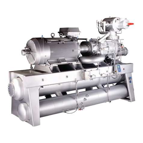
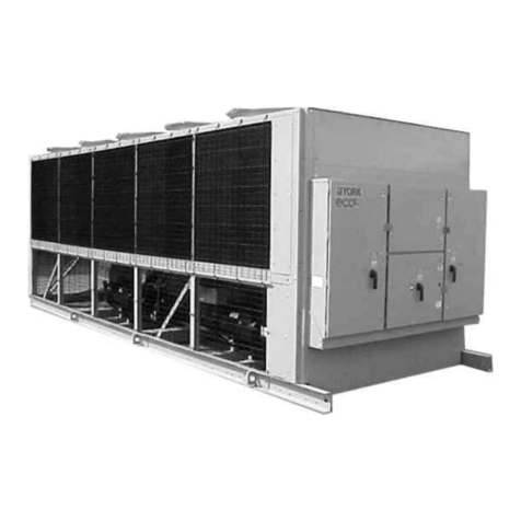
YORK YLAA chillers are manufactured to the highest
design and construction standards to ensure high
performance, reliability and adaptability to all types of
air conditioning installations.
The unit is intended for cooling water or glycol solutions
and is not suitable for purposes other than those
VSHFL¿HGLQWKLVPDQXDO
This manual contains all the information required for
correct installation and commissioning of the unit,
together with operating and maintenance instructions.
The manuals should be read thoroughly before
attempting to operate or service the unit.
All procedures detailed in the manuals, including
installation, commissioning and maintenance tasks
PXVWRQO\EHSHUIRUPHGE\VXLWDEO\WUDLQHGDQGTXDOL¿HG
personnel.
The manufacturer will not be liable for any injury or
damagecausedbyincorrectinstallation,commissioning,
operation or maintenance resulting from a failure to
follow the procedures and instructions detailed in the
manuals.
Warranty
Johnson Controls warrants all equipment and materials
against defects in workmanship and materials for a
period of eighteen months from date of shipment,
unless labor or extended warranty has been purchased
as part of the contract.
The warranty is limited to parts only replacement and
shipping of any faulty part, or sub-assembly, which has
failed due to poor quality or manufacturing errors. All
claims must be supported by evidence that the failure
has occurred within the warranty period, and that the
unit has been operated within the designed parameters
VSHFL¿HG
All warranty claims must specify the unit model, serial
number, order number and run hours/starts. Model
and serial number information is printed on the unit
LGHQWL¿FDWLRQSODWH
7KHXQLWZDUUDQW\ZLOOEHYRLGLIDQ\PRGL¿FDWLRQWRWKH
unit is carried out without prior written approval from
Johnson Controls.
For warranty purposes, the following conditions must
EHVDWLV¿HG
The initial start of the unit must be carried out by trained
personnel from anAuthorized Johnson Controls Service
Centre.
Only genuine Johnson Controls approved spare parts,
oils, coolants, and refrigerants must be used.
All the scheduled maintenance operations detailed in
WKLVPDQXDOPXVWEHSHUIRUPHGDWWKHVSHFL¿HGWLPHV
E\VXLWDEO\WUDLQHGDQGTXDOL¿HGSHUVRQQHO
Failure to satisfy any of these conditions will
automatically void the warranty.
Standards for Safety
YLAA chillers are designed and manufactured within an
EN ISO 9001 accredited organisation and in conformity
with the following European Directives:
xMachinery Directive (2006/42/EC)
xEMC Directive (2004/108/EC)
xPressure Equipment Directive (97/23/EC)
xSafety Code for Mechanical Refrigeration
EN378-2 (2008)/A2 (2012) [Safety accessories
according to essential requirementsin PED
paragraph 2.11.1 have been calculated according
to EN13136:2001/A1:2005 and are not following
the requirements in EN378-2:2008 paragraph
XQOHVVGXDOUHOLHIYDOYHVDUH¿WWHG@
xSafety of machinery - Electrical Equipment of
Machine EN 60204-1 (2006)
xGeneric emissions and immunity standards for
industrial environment EN61000-6-4:2007 &
61000-6-2:2005
xISO 9614 – Determination of sound power levels
of noise sources using sound intensity
xConform to CE Testing Services for construction of
chillers and provide CE Listed Mark
Fluorinated Greenhouse Gases
x7KLV HTXLSPHQW FRQWDLQV ÀXRULQDWHG JUHHQKRXVH
gases covered by the Kyoto Protocol.
xThe global warming potential of the refrigerant
(R410A) used in this unit is 1720.
xThe refrigerant quantity is stated in the Physical
Data table of this document.
x7KHÀXRULQDWHGJUHHQKRXVHJDVHVLQWKLVHTXLSPHQW
may not be vented to the atmosphere.
x7KLVHTXLSPHQWVKRXOGRQO\EHVHUYLFHGE\TXDOL¿HG
technicians.
Responsibility for Safety
Every care has been taken in the design and
manufacture of the unit to ensure compliance with
the safety requirements listed above. However, the
individual operating or working on any machinery is
primarily responsible for:
Personal safety, safety of other personnel, and the
machinery.
Correct utilization of the machinery in accordance with
the procedures detailed in the manuals.
