Johnson Controls 520 User manual

P/N IM-520/MH Rev. E 1*CWSI-IM-520MHE*
© 2017 Johnson Controls. All rights reserved. All specifications and other information
shown were current as of document revision date and are subject to change without notice.
Low Frequency Sounder Model 520(R)(W)
Mini Horn Sounder Model MH(R)(W)
Description:
The Model 520 and MH are self-contained wireless audible notification devices which comply
with UL464 and NFPA 72 when installed in accordance with this manual. The sounders are
designed for use in sleeping areas as well as common areas within protected premises. The
model 520 is a low frequency sounder capable of annunciating temporal 3 or 4 pattern and
the MH is a piezo type sounder which produces the temporal 3 pattern. The 520/MH are fully
supervised for tamper, low battery, output driver fault and RF signal integrity. The individual
models can also be synchronized by interconnecting them. The sounders are powered by
3.6 volt lithium batteries as listed under the specifications section of this manual and the label
on the product. The Models 520 and MH are intended to be used with CWSI Fire Alarm
Control Panels. Refer to the control panel manual for compatibility details.
Installation:
The Model 520/MH must be installed and maintained in accordance with the National
Fire Protection Association’s Standards (NFPA), the National Electrical Code and all
local fire and electrical requirements. The 520/MH is to be installed in an indoor dry
location. Exposure to weather or corrosive conditions may damage the unit.
Locate a few accessible locations that are not prone to tampering or accidental damage.
Sound db output level, reliable RF signal, repeater depth and mounting method are important
factors when deciding on an installation location. Refer to the individual sections in this
manual to perform the sound level and signal survey testing. Sound output level and RF
signal survey tests must be conducted prior to and after mounting the product. Once
successful sound and signal survey tests have been completed the 520/MH can be mounted.
Mounting options include single gang, dual gang, 4” conduit box or surface mount directly to
the wall. When mounting directly to the wall the mounting surface should be relatively flat
and be capable of accepting screws or anchors. Always install the product vertically
observing the UP and arrow in the back box as shown in figure 1. Any other mounting position
will result in tamper troubles on the control panel. Mount the product in the desired location
then place the control panel in enrollment mode and install the batteries as shown in figure
2. Refer to the control panel manual for enrollment procedures. Observe polarities marked
on the battery holders. There is one battery for the RF circuitry and two for the sounder driver
circuitry. The RF battery is p/n ER34615 and has a black line around the outside of the battery
at the + terminal. The sounder driver batteries are p/n ER34615M and have a gold line around
the outside of the battery at the + terminal. Warning: Always install a new battery of one
of the approved types as listed in the Specifications section of this manual and the
product label. Two short beeps will be emitted from the sounder along with a power up reset
trouble showing the product serial number at the control panel indicating successful
enrollment. Attach the front of the 520/MH to the back box by inserting the tabs on the bottom
of the front into the slots on the back box then hinge the front closed and secure it with the
two supplied screws (figure 3). Perform sound, RF signal and alarm tests as specified in this
manual after installation is complete.

P/N IM-520/MH Rev. E 2
© 2017 Johnson Controls. All rights reserved. All specifications and other information
shown were current as of document revision date and are subject to change without notice.
FIGURE 1
Sound Test:
The 520/MH notification devices incorporate a method to allow the installer to perform a 5
second temporal 3 db sound level test. The test can be performed without activating an
alarm on the programmed zone(s). To initiate the test hold a magnet up to the face of the
appliance at the test position shown in figure 4 for approximately 5 seconds. There is a
small dimple in the plastic on the cover to help find the test position. When activated, the
test will produce the temporal 3 pattern for 5 seconds to allow a db sound output
measurement to be obtained at the desired location. This test can be performed without the
unit being enrolled into a panel or in a network making for a good tool for pre-installation
testing.
Loud/Norm jumper (520 only):
The model 520 has an optional loud setting of the sound level output. The J8 jumper can
be selected for either norm or loud sound dBA output. The loud setting will increase the
sound output approximately 1.5 dBA from the norm setting. This additional sound output
level can be used where marginal or inacceptable sound dBA readings are obtained in an
area. This boost in sound output could result in required sound levels being achieved in lieu
of adding additional sounders or relocation. For the best battery life always leave the J8
jumper in the norm position.

P/N IM-520/MH Rev. E 3
© 2017 Johnson Controls. All rights reserved. All specifications and other information
shown were current as of document revision date and are subject to change without notice.
FIGURE 2
Signal Test:
The test must be performed while the 520/MH is held in its intended mounting location. The
unit must be powered up and in communication with a repeater or control panel. Initiate the
test by momentarily placing a strong magnet on the 520/MH front cover at the location shown
in figure 3. The sounder will beep once. A delay of up to 15 seconds will occur followed by
either one or two beeps. One beep indicates an unacceptable location and two beeps
indicate an acceptable location. If only one beep is heard then relocate the model 520/MH
mounting position closer to the nearest repeater or control panel and perform the test again.
Continue this procedure until 2 beeps are achieved. Do not mount the appliance detector
unless 2 beeps are heard when performing 5 consecutive signal tests. This test must be
performed before and after product installation. The maximum repeater depth between any
520/MH and any alarm device is 22. This depth insures 10 second alarm to horn activation.
Note: The 520/MH must be in communication with a survey repeater, enrolled repeater or
control panel to perform the test. Refer to the repeater and/or control panel for more
information.

P/N IM-520/MH Rev. E 4
© 2017 Johnson Controls. All rights reserved. All specifications and other information
shown were current as of document revision date and are subject to change without notice.
FIGURE 3
Programming:
The 520/MH must be enrolled into the CWSI Fire Alarm Control Panel before it can be
programmed to activate its sounder on receipt of an alarm. The Model 520/MH will not
respond to alarms unless it is enrolled into a compatible control panel and
programmed to activate. The 520/MH can be programmed with up to 3 different zones
and various silencing options. The temporal 3 pattern is to be used for evacuation only.
Refer to the control panel installation instructions for further details on programming
options.
Synchronization
The 520/MH sounders can be synchronized by interconnecting them with a single wire pair.
The wiring should be in conduit and contained within one room. Note: Interconnection of
models 520 and MH is not recommended as synchronization is not guaranteed
between different models. When connected together the sounders will synchronize their
temporal 3 and 4*(520 only) patterns when multiple sounders are activated. To achieve
synchronization the sounders must be both correctly configured as master and slave(s) and
wired together. Master and slave selection is made by moving jumper J11 to either the “M”
(master) or “S” (slave) position. The first sounder in line must be configured as a Master
since it will sync all of the other connected units. The sounders connected to the master
must be configured as slaves to accept sync pulses from the master. The J11 Master/Slave
jumper position must be chosen prior to installing the RF battery as it is only read on power
up. Proper selection of the J11 jumper is also monitored for the following rules:
1. Single standalone sounders must be configured as a Master.
2. The first sounder of interconnected units must be a Master.
3. There can only be one master in a group of interconnected units.

P/N IM-520/MH Rev. E 5
© 2017 Johnson Controls. All rights reserved. All specifications and other information
shown were current as of document revision date and are subject to change without notice.
Wiring between the sounders is accomplished by connecting between them using TB1
input and output. Install conduit into the knockout located at the bottom edge of the back
box. Use this conduit to run wires between units. Terminals 1+2 are sync output and 3+4
are sync input. Wiring must start at the master. Connect the sync output from the master to
the sync input of the first slave. Observe polarity of the connections. Terminal 1 on the
master should go to terminal 4 on the slave and terminal 2 on the master should go to
terminal 3 on the slave. To connect more than one slave, continue to wire from output to
input slave to slave until the last one is connected. Refer to figure 4 for the wiring diagram
of interconnected sounders.
Problems with wiring or improper jumper settings will cause an EOL/Config trouble at the
control panel. Check the wiring and jumper settings and correct any wiring/configuration
issues. Note: The sounders will still activate as programmed even if an EOL/Config
error is present on the control panel but they may not be synchronized.
FIGURE 4
Pseudo Master Feature
If a slave loses its sync communication with its master it will automatically switch to pseudo
master mode. In this mode the pseudo master will assume master functions and generate
supervision and sync pulses to keep connection integrity monitored and any other down

P/N IM-520/MH Rev. E 6
© 2017 Johnson Controls. All rights reserved. All specifications and other information
shown were current as of document revision date and are subject to change without notice.
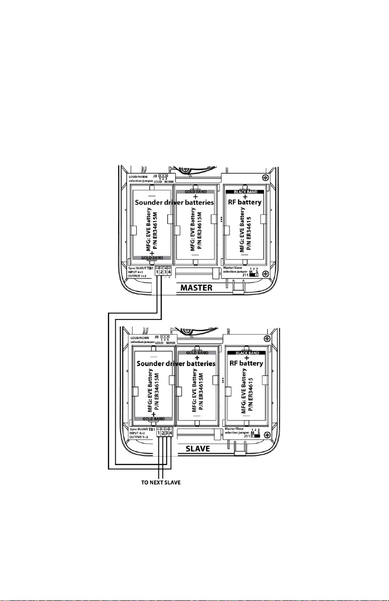
line slaves synchronized to it. If the original master resumes control then the pseudo
master will resort back to slave mode.
Alarm Testing
The 520/MH sounders must be tested after installation, programming, battery replacement
and following any maintenance. NOTE: Before testing, notify the proper authorities that
maintenance is being performed and the system will be temporarily out of service.
A basic sounder test can be accomplished by performing the sound test described in this
manual. This test does not check for proper programming of zones to the sounder or
functionality of all circuitry. A full system test to activate the sounders via zones is mandatory
to test full functionality of the sounder.
To test the sounder perform the following:
1. Activate an alarm from a device whose zone matches a zone programmed into the
sounder.
2. Verify activation of the sounder and measure db output at the desired location.
3. Verify the sounder operates for a minimum of 60 seconds.
4. Verify no troubles are received from the sounder during the alarm test.
5. Reset the control panel and verify the sounder silences.
6. Verify no troubles are received from the sounder after the alarm test.
7. Repeat the above for each sounder.
A failure of any sounder to successfully complete the alarm test should be checked and
repaired or replaced.
Low battery/Low battery2:
The model 520/MH periodically tests both the sounder driver and RF batteries for a low
battery condition. If a low battery is detected a trouble condition is transmitted and repeated
every 90 seconds. The RF and sounder batteries send two uniquely identified low battery
troubles. If the RF battery is low a low battery trouble will be present on the panel. If the
sounder driver batteries are low a low battery2 trouble signal will be present on the control
panel. If more than one type of trouble exists, all will be repeated in increments of 90 seconds.
Always replace the low battery with a new one. Refer to the Battery Installation and
Replacement section for instructions on battery replacement.
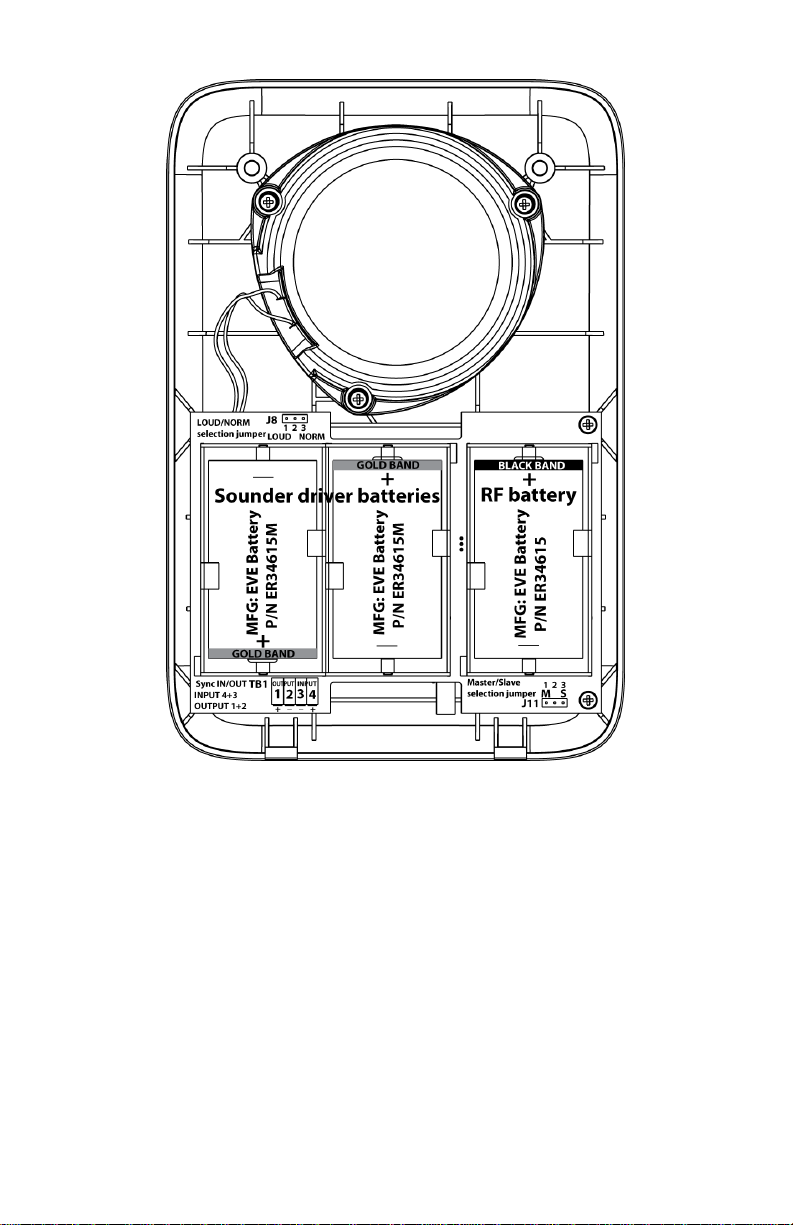
Battery Installation and Replacement:
Warning: Always install new battery/batteries of one of the approved types as listed in
the Specifications section of this manual and the product label. The RF and sounder
driver batteries are two different part numbers. Be sure to install the correct p/n battery
in the appropriate holder(s). Observe correct polarity as marked in the battery holders.
To replace the battery:
1. Place the Control Panel in Test mode to prevent any unwanted alarms.
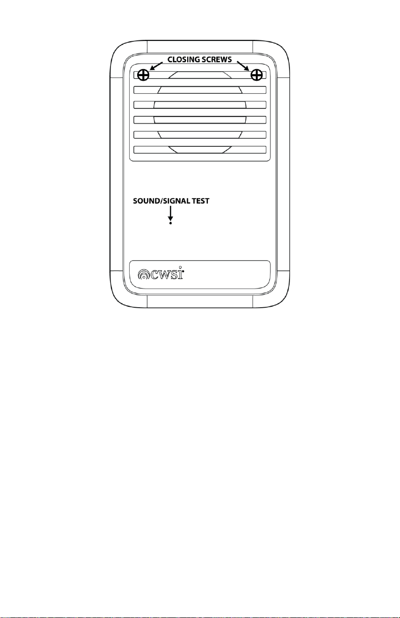
2. Remove the front of the 520/MH by removing the two closing screws then separate the
front and back starting at the top of the case. Lift off the front then remove the old battery/
batteries and dispose of properly.
3. To insure proper power down sequence, wait a minimum of 20 seconds before installing
a new battery.
4. Install new battery/batteries in the battery compartment following the polarity diagram
inside the compartment. When replacing the sounder driver batteries always replace
both batteries with new ones. A power up reset trouble signal should be indicated on the
Control Panel within 30 seconds. A tamper trouble will also be indicated if the front cover is
not attached to the base.
Note: When changing only the sounder driver batteries you must remove and reinstall
the RF battery after replacing the sounder driver batteries in order to reset the
lowbattery2 trouble signal from the memory of the 520/MH. The RF battery does not

P/N IM-520/MH Rev. E 7
© 2017 Johnson Controls. All rights reserved. All specifications and other information
shown were current as of document revision date and are subject to change without notice.
need to be replaced with a new one to reset the lowbattery2 trouble. Always wait 20
seconds between removing and installing any battery in the 520/MH.
5. Reinstall the front cover onto the mounting base by inserting the bottom tabs into the slots
in the back box then hinge the front cover closed. Secure the front cover to the back the
closing screws.
8. Perform the alarm test as described in this manual.
9. Remove the panel from test mode.
Power Up Reset:
The Models 520/MH will report this trouble within 30 seconds when powered up. This is
normal. If a power up reset occurs any time after the initial indication then the transmitter is
malfunctioning. Replace the unit.
Test Failure:
The Model 520/MH transmits a periodic test signal to the control panel. This trouble condition
will be displayed within 200 seconds on the control panel if it does not receive the test
transmission. The sounder may be out of reception range of a repeater or control panel or
may have an internal problem. Perform the signal test described in this manual to determine
if there is a reception problem. Note: This trouble is self-restoring on CP-3500D or newer
FACP’s.
Tamper:
The 520/MH contains a built in tilt switch that will cause a Tamper signal to be transmitted if
the front cover of the sounder is removed. A tamper signal is transmitted and repeated every
90 seconds until the front cover is put back into position. Where more than one type of trouble
exists, all will be repeated in increments of 90 seconds. Note: The tamper trouble is self-
restoring on CP-3500D or newer FACP’s.
EOL/Config:
The 520/MH monitors correct setting of the master/slave jumper as well as unit to unit
interconnecting wiring integrity. If either the J11 jumper setting is incorrect or wiring integrity
is compromised then this trouble will be present on the control panel. When the trouble is
caused by incorrect J11 position then the jumper setting should be corrected and the RF
battery will need to be removed and reinstalled to correct the trouble. If the trouble is due to
a wiring fault then simply fixing the fault will restore the trouble on the control panel. Always
wait 20 seconds between removing and reinstalling a battery in the 520/MH.
Hardware Fault
The 520/MH monitors the sounder driver circuit output voltage. An insufficient output
voltage from this circuit could result in reduced dBA sound output. A hardware fault trouble
will be displayed. Sound may not be emitted from the unit when this trouble is present as
the voltage is insufficient to produce the correct sound. A severely low sounder driver
battery may produce this trouble if left unchanged after the initial lowbattery2 signal was
sent and an alarm occurs.

P/N IM-520/MH Rev. E 8
© 2017 Johnson Controls. All rights reserved. All specifications and other information
shown were current as of document revision date and are subject to change without notice.
Specifications:
Battery Type: RF 3.6 Volt Lithium EVE ER34615; Sounder driver (2) ER34615M
Battery Life: 12 Months Minimum
Battery Replacement: Upon Low battery report and/or during maintenance.
Average Standby Current Model 520(R)(W): Norm/Loud 15ua/25ua @7.2Vdc;
Average Alarm Current Model 520(R)(W): Norm/Loud 150ma/150ma @7.2Vdc;
400ua@3.6Vdc
Average Standby Current Model MH(R)(W): [email protected]; [email protected]
Average Alarm Current Model MH(R)(W): [email protected]; [email protected]
Sounder: MH exceeds 75dBA@10’ temporal 3; 520 exceeds 75dBA@10’ temporal
3 or 4 pattern normal and loud modes.
Low battery nominal: RF 3.3Vdc; Sounder driver 520/MH 7.1Vdc
Operating Temperature Range: 32F to +120F.
Operating Humidity Range 15% to 95%
Storage Temperature Range 32F to +86F
Testing: Follow this manual and NFPA 72 or local requirements.
Transmission: In compliance with FCC part 15
Test Transmission: Every 90 seconds
Overall dimensions 8.25”x 5.5” x 2.5”
Weight 19.2 oz. without battery
FCC Statement
Important: Any changes or modifications not expressly approved by the party responsible for
compliance could void the user’s authority to operate the equipment
This device complies with part 15 of the FCC Rules. Operation is subject to the following two
conditions: (1) This device may not cause harmful interference, and (2) this device must
accept any interference received, including interference that may cause undesired operation.
Disclaimer
The information contained in this document is believed to be accurate and reliable at the time
of printing. Known corrections or omissions may be found on errata sheets included in the
various product manuals. However, CWSI a Tyco Fire & Security GmbH Company (CWSI)
may not be held accountable for errors or omissions in this or other CWSI publications. No
license is granted by implication or otherwise under any patent rights of CWSI. Applicable
terms and conditions can be found at
http://tycofsbp.com/TFPPTerms_of_Sale/TFPPTerms_of_Sale.pdf
This manual suits for next models
5
Table of contents