Teleflex Marine SeaSTAR OPTIMUS Steering System User manual

OPERATION INSTRUCTIONS
AND USERS MANUAL
www.teleflexmarine.com
ISO 9001
Electronic Power Steering
for Outboard Powered Vessels
MANUFACTURED BY
MARINE CANADA ACQUISITION
LIMITED
PARTNERSHIP DBA TELEFLEX
CANADA
MEMBER

© 2012 Teleflex Marine, Inc. Optimus Operations Manual, Rev. A
All information, illustrations and specifications in this manual are
based on the latest information available at the time of publishing.
The illustrations used in this manual are intended as representative
reference views only. Moreover, because of our continuous product
improvement policy, we may modify information, illustrations and/
or specifications to explain and/or exemplify a product, service or
maintenance improvement. We reserve the right to make any change
at any time without notice.
For the latest information, go to www.teleflexmarine.com
All Rights Reserved:
No part of this publication may be reproduced or used in any form
by any means without the written permission of Teleflex Marine
Incorporated.
©2012 Teleflex Marine.
NMEA 2000®is a registered trademark of the National Marine
Electronics Association.
To the End User (Owner)
Thank you for choosing an OptimusTM Steering System by Teleflex
Marine. This User’s manual contains all of the information that you
will require for safe use of your steering system and must remain on
the boat.
Optimus is a trademark of Teleflex Marine.
is a registered trademark of the American Boat & Yacht
Council (http://www.abycinc.org)
i

© 2012 Teleflex Marine, Inc. Optimus Operations Manual, Rev. A
CAUTION
WARNING
IMMEDIATE HAZARDS WHICH, IF NOT ACTED UPON, WILL RESULT
IN SEVERE PERSONAL INJURY OR DEATH.
HAZARDS OR UNSAFE PRACTICES WHICH, IF NOT ACTED UPON,
COULD RESULT IN SEVERE PERSONAL INJURY OR DEATH.
Hazards or unsafe practices which COULD result in minor injury or
product or property damage.
Information which is important to proper use or maintenance, but is
not hazard-related.
Throughout this publication, Dangers, Warnings and Cautions
(accompanied by the International Hazard Symbol ) are used to
alert the user to special instructions concerning a particular service
or operation that may be hazardous if ignored, performed incorrectly,
or carelessly.
Observe Them Carefully!
These “safety alerts” alone, cannot eliminate the hazards that
they signal. Strict compliance to these special instructions when
operating and maintaining, plus “common sense” operation, are
major accident prevention measures.
Notice to the Operator
ii

© 2012 Teleflex Marine, Inc. Optimus Operations Manual, Rev. A
iii
INDEX
1.0 Safety Instructions ............................................................... 1
Safety Labels...................................................................... 3
Abbreviations...................................................................... 5
2.0 Introduction
2.1 Welcome ..................................................................... 6
2.2 Optimus System Overview............................................. 6
2.3 Optimus EPS System Diagram....................................... 7
3.0 First Time Operation ............................................................. 8
3.1 Locate the Following Steering System Components......... 8
3.2 Initial Start Up ........................................................... 12
3.3 System Inspection...................................................... 13
3.4 Installation Checks..................................................... 15
3.5 Initial Sea Trial ........................................................... 18
4.0 System Use........................................................................ 19
4.1 Before Each Use ........................................................ 19
4.2 Multiple Stations ........................................................ 20
4.3 Autopilot Operation .................................................... 18
5.0 CANtrak Display ................................................................ 21
5.1 Purpose.................................................................... 21
5.2 CANtrak Display Navigation ......................................... 22
5.3 CANtrak Display Map – All Helms Active ....................... 23
5.4 All Helms Active Screens ............................................ 24
6.0 System Faults & Hazards .................................................... 28
6.1 Hazard Definitions ...................................................... 28
6.2 System Fault Handling ................................................ 29
6.3 Buzzer....................................................................... 36
6.4 Reduced Per formance ................................................ 36
6.6 Steering Fluid ............................................................ 36
7.0 Maintenance ...................................................................... 37
8.0 Troubleshooting.................................................................. 39
9.0 Replacement Parts............................................................. 40
9.1 SeaStar Electronic Power Steering Fluid ....................... 40
10. Warranty ............................................................................ 41
10.1 Statement of Limited Warranty .................................. 41
10.2 Return Goods Procedure .......................................... 41
APPENDIX A - Specifications..................................................... 42

© 2012 Teleflex Marine, Inc. Optimus Operations Manual, Rev. A 1
1.0 SAFETY INFORMATION
The safety information provided below is intended to inform
you of the dangers that may be present before, during and
after use. It is critical that you read and understand ALL the
points noted.
The safe operation of the steering system is dependant upon proper
installation and maintenance, common sense, safe judgement and
the knowledge/expertise of the operator. Every installer/user of the
steering system should know the following requirements ‘before’
installing/using the steering system.
If you have any questions regarding any of these warnings, contact
Teleflex Marine.
To reduce risk of severe injury or death:
Perform a system inspection as outlined below. Refer to Section 3.3
for further details.
1. Check steering fluid level in all steering pumps.
2. Verify immediate steering response when turning steering
wheel(s).
3. Inspect all steering hoses, fittings and mechanical and electrical
cables for wear, kinks, or leaks.
4. Check for binding, loose, worn or leaking steering or shift/throttle
control components.
5. Verify proper shift and throttle response for all control handles.
6. Verify that no alarms or warnings are shown on the CANtrak
display.
DO NOT OPERATE BOAT IF ANY COMPONENT IS NOT IN PROPER
WORKING CONDITION.
Prior to every use
WARNING
WARNING The Optimus EPS System MUST be installed by ONLY an authorized
Teleflex Marine dealer.
1. Always wear a Coast Guard Approved personal flotation device
(PFD) and use an engine shut-off cord (lanyard).
2. Read and understand this User’s manuals and the Quick
Reference Card provided with your steering components.
3. Optimus components are highly engineered and safety tested
to ensure system integrity. DO NOT substitute any component
with non-Optimus components, as this may compromise system
performance/reliability.

© 2012 Teleflex Marine, Inc. Optimus Operations Manual, Rev. A
2
Safety Information Continued
Rinse off SmartCylinders thoroughly using “fresh, clean water” only.
Do NOT rinse PCM or pumps.
• Cleaninguidscontainingammonia,acidsoranyothercorrosive
ingredients MUST NOT be used for cleaning any par of the
Optimus Steering Controls.
Maintain Optimus Steering System as directed in Section 7 of this
Manual.
Keep our waters clean for all current and future users. Dispose of
ALL fluids in accordance with your local regulations.
After use
Maintenance
1. WEAR A COAST GUARD-APPROVED PERSONAL FLOTATION DEVICE
(PFD).
2. Attach engine shut-off cord (lanyard) to your pfd.
3. Never allow anyone not familiar with the operation of the steering
system to operate the boat at ANY time.
4. Know and adhere to the operator restrictions for you area
including:
•FederalLaws/Regulations,
•StateLaws/Regulationsand
•MunicipalLaws/Regulations.
DO NOT OPERATE BOAT IF ANY COMPONENT IS NOT IN PROPER
WORKING CONDITION.
During use

© 2012 Teleflex Marine, Inc. Optimus Operations Manual, Rev. A 3
Safety Labels
NOTE: The labels below should call attention to the possible
hazards associated with the equipment shown later in this manual
(see Section 3.1)
WARNING
Pump Control Module
(PCM) Label
Hydraulic Pump Label
CAUTION
HOT

© 2012 Teleflex Marine, Inc. Optimus Operations Manual, Rev. A
4
Safety Labels Continued
SmartCylinder Label
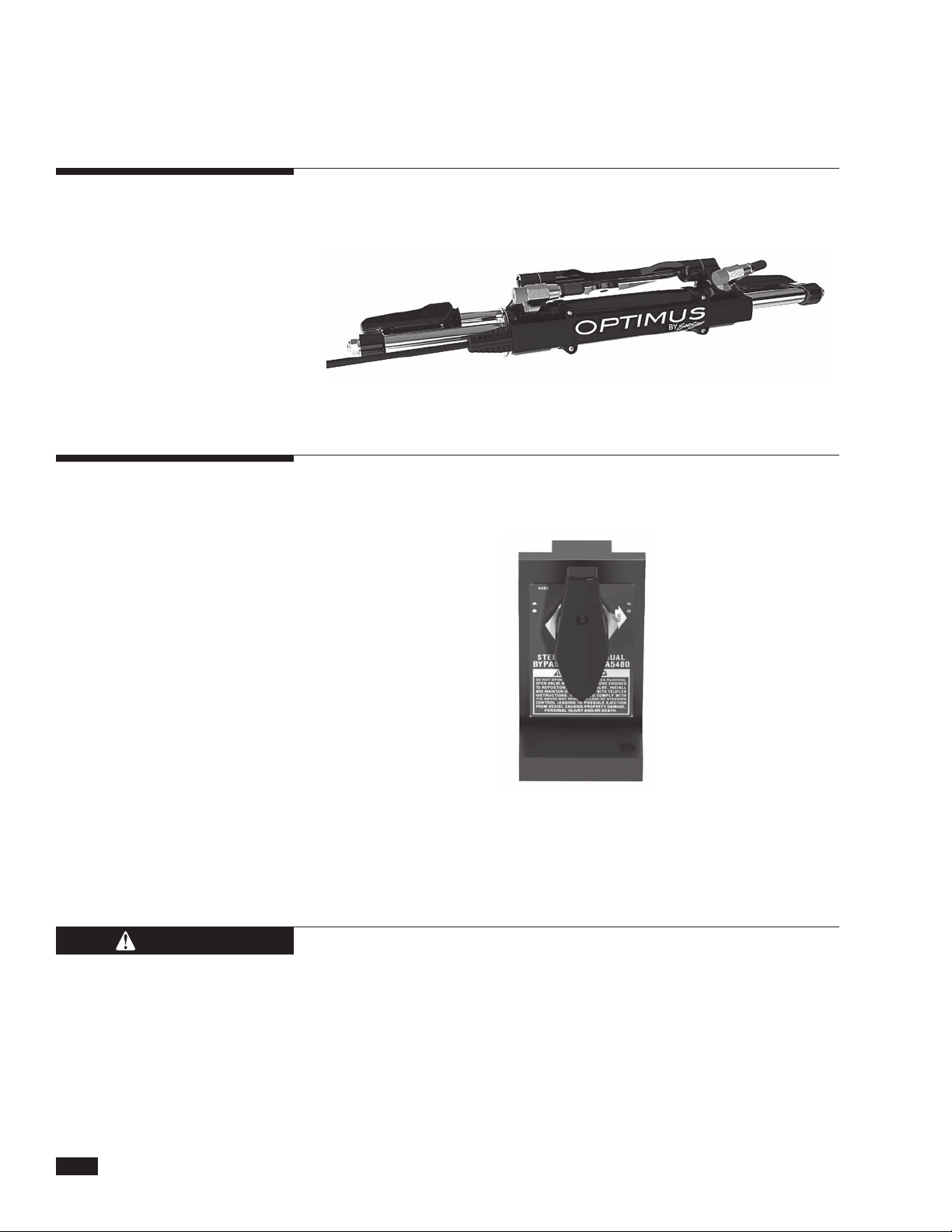
Steering Service
Valve Label
(May be installed if the valve is hidden from view.)

© 2012 Teleflex Marine, Inc. Optimus Operations Manual, Rev. A 5
ABYC American Boat & Yacht Council
AP Autopilot
CAN Control Area Network
EPS Electronic Power Steering
GPS Global Positioning System
INFO Information
HI High
LO Low
MPH Miles Per Hour
NMEA National Maritime Electronics Association
NMEA 2000®The special protocol for digital communication on a
CAN Bus
RPM Revolutions Per Minute
STBD Starboard (right)
Note: Some abbreviations not listed here may be found in their
respective sections.
ABBREVIATIONS
The following abbreviations are used in this manual:

© 2012 Teleflex Marine, Inc. Optimus Operations Manual, Rev. A
6
2.0 INTRODUCTION
2.1 Welcome
Welcome to the world of electronic power steering. Please take
a few minutes to go thru the System Overview and the First Time
Operation sections to assure your safety and to get the most
enjoyment from the Optimus EPS steering system.
2.2 Optimus EPS
System Overview
A typical Optimus EPS system consists of an Electronic Helm located
behind the steering wheel which is electrically connected to a Pump
Control Module. This module converts the steering wheel action
to electrical signals which operate Hydraulic Pumps. These pumps
move the smart steering cylinders (SmartCylinders) at each engine.
A position sensor is part of the SmartCylinders and provides
engine position information back to the Pump Control Module.
Service Valves are installed between the Hydraulic Pumps and the
SmartCylinders to allow for manual positioning of the engines should
a fault occur or for use by the technician during servicing.
A CANtrak Display shows system operation and fault warnings. The
CANtrak Display also permits system sensitivity and configuration
adjustments.
The Optimus EPS system includes many advancements to make
the system as failsafe as possible. These include redundant
sensors, fault-tolerant communications, self-monitoring and fault
communications to notify and advise the operator in case of fault.
NOTICE

© 2012 Teleflex Marine, Inc. Optimus Operations Manual, Rev. A 7
2.3 Optimus EPS System Diagram

© 2012 Teleflex Marine, Inc. Optimus Operations Manual, Rev. A
8
3.0 FIRST TIME OPERATION
3.1 Locate the Following
Steering System Components
3.1.1 Electronic Helm(s)
The steering wheel is attached to this unit and it may be located
immediately under the wheel or just behind the dash panel. The
images below show typical helms.
These are supplied by the installer and may be mounted in a variety
of locations. Check near the batteries, in the circuit breaker box, or
near the Pump Control Modules or Hydraulic Pumps. There should
be a 60 amp breaker for each PCM power feed.
3.1.2 Circuit Breakers for Optimus EPS System
EPS Front Mount Helm EPS Rear Mount Helm
EPS Classic Tilt Helm EPS Sport Plus Tilt Helm

© 2012 Teleflex Marine, Inc. Optimus Operations Manual, Rev. A 9
This is located in a dry area and can usually be found inside the
center console, in the area behind the dash, or in a compartment
near the engines or batteries. The PCM is always located close to
the Hydraulic Pumps. There will be one PCM on twin engine boats.
Hydraulic Pumps are located near the PCM. They can usually be
found in a compartment near the engines, the center console or
behind the dash. There is one pump for each engine. Note: these
pumps look a lot like the trim pumps that tilt the engines but can
be distinguished by the decal and the green/blue SeaStar Electronic
Power Steering Fluid. The pumps have the steering fluid reservoir
and this is where the fluid level is checked and steering fluid is
added.
3.1.3 Pump Control Module (PCM)
3.1.4 Hydraulic Pumps
© 2012 Teleflex Marine, Inc. Optimus Operations Manual, Rev. A
10
On outboard boats these are always located just below the engine
cowling and are attached to the engine tiller arm. There will be one
SmartCylinder for each engine.
These are located in the hydraulic lines that go from the Hydraulic
Pumps to the SmartCylinders. There is one for each engine. These
are used for servicing and emergency operation.
3.1.5 SmartCylinders
3.1.6 Steering Service Valves
WARNING Wear a coast guard-approved personal flotation device (PFD) when
manually realigning engines.
The steering service valves permit the bypass of the EPS system
and allow the engines to be manually positioned. They should only
be used in the event of an EPS system failure. Instructions on how to
proceed will be supplied on the CANtrak display or in Section 6.2.5.

© 2012 Teleflex Marine, Inc. Optimus Operations Manual, Rev. A 11
There is a display at each helm station that shows the system status
and allows system adjustments.
3.1.7 CANtrak Display

© 2012 Teleflex Marine, Inc. Optimus Operations Manual, Rev. A
12
3.2
Initial Start Up
Turning on the ignition switch will turn on the Optimus EPS system.
The CANtrak Display will turn on and the steering will become active
at ALL helms.
After reading the initial warning screen press the INFO button and
follow the prompts for a system inspection.
All Helms Active
Splash Screen
Initial Warning System Check 1 System Check 2 System Check 3
INFO NEXT NEXT
OK
3 SEC INTERVAL
BACK
OK
BACK
WARNING On multiple helm station boats all helms are active when the
Optimus EPS is turned on. This is the same you would find on a
conventional hydraulic steering system.

© 2012 Teleflex Marine, Inc. Optimus Operations Manual, Rev. A 13
1. Check steering fluid level in all steering pumps.
Each Optimus hydraulic pump has a steering fluid reservoir.
Ensure the fluid level is between the MIN and MAX marks on
the reservoir as shown in the figure below. Use only SeaStar
Electronic Power Steering Fluid in the Optimus EPS System.
Failure to adhere to these warnings may result in loss of boat
control, leading to possible ejection from vessel; causing property
damage, personal injury and/or death.
3.3 System Inspection
2. Verify immediate steering response when turning steering
wheel(s).
Turn the steering wheel slowly to port and to starboard and make
sure the engines follow the commands. Watch that the hoses and
cables move freely without any snags or hang-ups.
3. Inspect all steering hoses, fittings and mechanical and
electrical cables for wear, kinks, or leaks.
Check all steering hoses and fittings between the pump, service
valves and cylinders for any signs of leakage, kinking, wear or
chafing. Check all electrical and mechanical cabling for abrasion,
wear, rubbing or chafing. Check that all connections are tight and
free of corrosion.

© 2012 Teleflex Marine, Inc. Optimus Operations Manual, Rev. A
14
System Inspection Continued
4. Check for binding, loose, worn or leaking steering or shift/
throttle control components.
Check all shift and throttle cables for signs of wear, damage or
chafing. Check that all linkages and cables move freely and are
not binding or corroded.
5. Verify proper shift and throttle response for all control handles.
Check that all shift and throttle levers operate freely and cause
the engines to shift accordingly. Put the engines in neutral idle
mode and confirm that the throttle responds correctly and returns
to idle.
6. Verify that no alarms or warnings are shown on the CANtrak
display.
If any warnings are found, follow the instructions on the CANtrak
screen or refer to Section 6 of this manual before proceeding
Read the System Inspection steps on the CANtrak display and
acknowledge them by pressing the right hand most button under
OK.
WARNING
WARNING It is recommended the full system inspection be reviewed on a
regular basis to retain familiarity.
After becoming familiar with the system inspection process, the
operator can use the OK button to acknowledge that the system
inspection process was understood and completed and can then go
directly to the steering mode screen.
DO NOT OPERATE BOAT IF ANY COMPONENT IS NOT IN PROPER
WORKING CONDITION.

© 2012 Teleflex Marine, Inc. Optimus Operations Manual, Rev. A 15
3.4 Installation Checks
1. Interference Checks - Confirm that there is no interference
between the steering cylinder(s), splashwell or outboard engine
or any combination of these parts by performing the steps below.
At the same time for each step also check that the hoses and
cables are moving freely with no rubbing or binding (see figures
below and on right page).
a) With the engines fully tilted DOWN, turn the steering wheel from
hard over to hard over and confirm that no interference occurs.
b) With the engines fully tilted UP, turn the steering wheel from
hard over to hard over and confirm that no interference occurs.
c) Trim the port engine fully DOWN and the starboard engine fully
UP. Turn the steering wheel from hard over to hard over and
confirm that no interference occurs.
d) Trim the starboard engine fully DOWN and the port engine fully
UP. Turn the steering wheel from hard over to hard over and
confirm that no interference occurs.
To verify correct installation of the Optimus SmartCylinder, perform
the following installation checks when the boat is delivered and
after each boat servicing.
Failure to perform these checks may result in damage to the
SmartCylinder sensor and affect the safe operation of the boat’s
steering.
WARNING
If any issues are found during the installation checks, immediately
return the boat to the service dealer for those issues to be remedied.
CAUTION

© 2012 Teleflex Marine, Inc. Optimus Operations Manual, Rev. A
16
Installation Checks continued
Make sure that all cables and hoses move freely and that the
cylinders and engines are clear at steering extremes.
ENGINE SIDE VIEW, WHEN TILTED
Table of contents
Other Teleflex Marine Marine Equipment manuals


