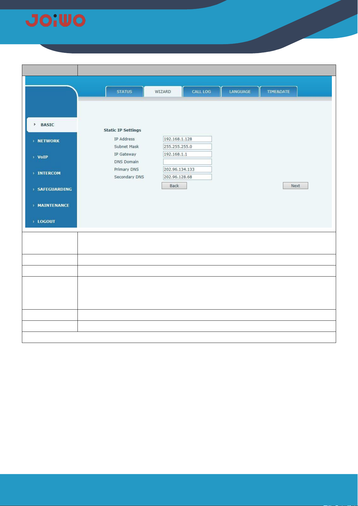
1.
Overview
JWAT921 waterproof telephone product is an environmental high-tech product that combines subways,
highways, power plants, petrol stations, docks, steel companies, etc., which have special requirements for
moisture, fire, dust, and frost protection. It is an indispensable and extremely ideal industry. Communication
products, which must be used together with switches.
1.1
Product Features
1.1.1
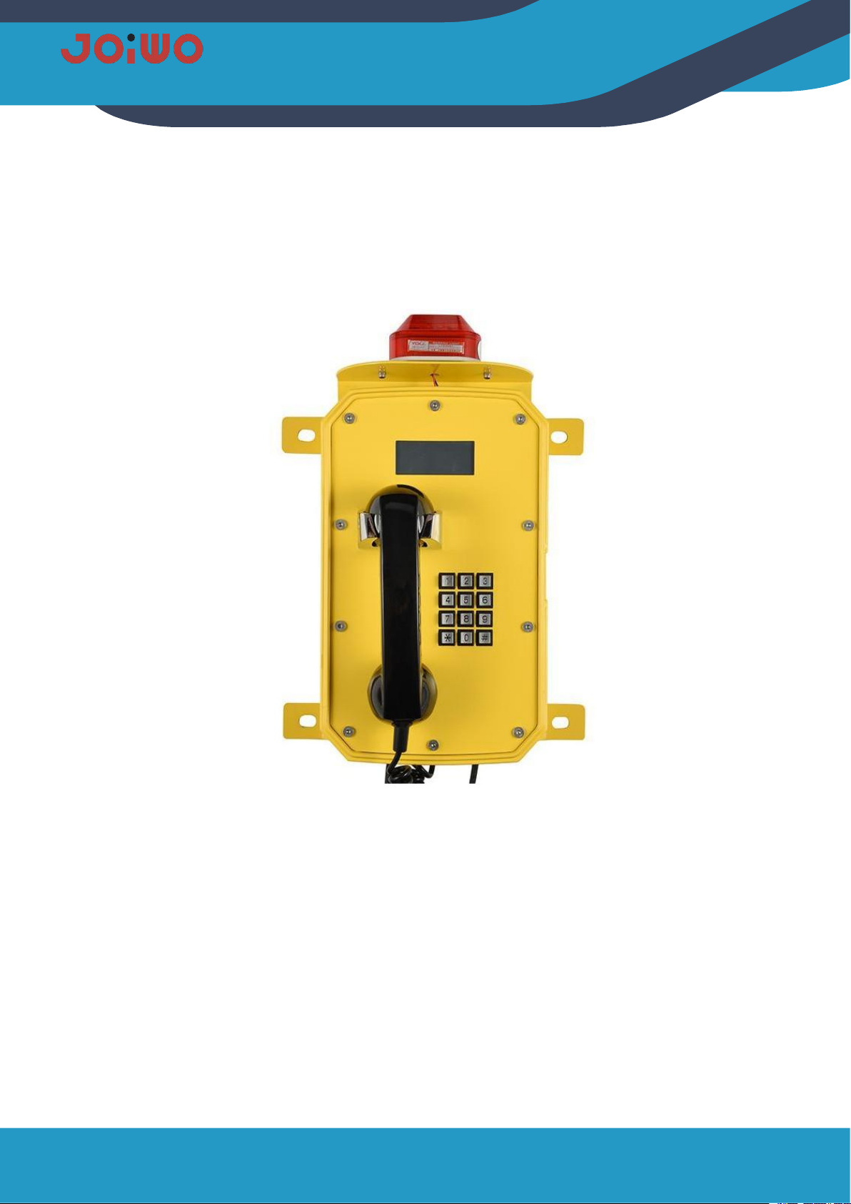
JWAT921 waterproof phone case is made of aluminum alloy die-casting, which has good impact
resistance and protection performance. The high-temperature powder on the surface is not electrostatically
sprayed to prevent static electricity. The circuit board adopts the concept of integrated design, and integrates the
basic call circuit and noise removal circuit in a machine. And preferably foreign well-known brand components.
After high and low temperature testing, procurement and production, the circuit undergoes strict protection
treatment, so that the environmental adaptability of the whole machine is further improved, and the phone
adopts an anti-noise handle.
1.2
Application
1.2.1
This Weatherproof Telephone Is Very Popular For subways, highways, power plants, petrol stations,
docks, steel companies and other environments that have special requirements for moisture, fire, noise, dust
and frost.
1.2.2
Ambient Temperature:-40°F~+140°F
1.2.3
Relative Humidity:≤95%( room temperature)
1.2.4
Atmospheric Pressure:80~110KPa
2.
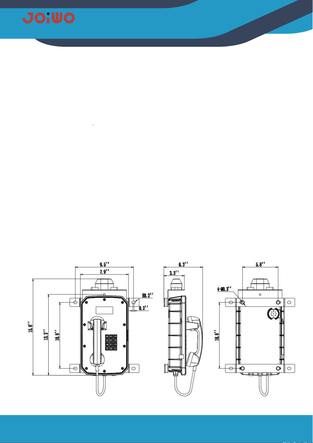
Product Structure Characteristics
2.1
The IP non-amplified phone with display screen consists of three parts: shell (including die-cast aluminum
shell, handle, keyboard, cold-rolled steel panel, warning light, etc.), electronic display and double-sided
integrated circuit motherboard.