ABB AB / Jokab Safety Varlabergsvägen 11, S-434 39, Sweden
www.jokabsafety.com
Instructions
Vital 1
Testing the safety functions
General information
Checking the safety functions of Vital 1 is normally easy to perform at a machine where Vital 1 is in operation. Do
not disconnect the VITAL 1 for testing. This should only take a few minutes. The normal check is performed by
using the safety devices connected to Vital 1 to verify that the safety functions are working properly. Proper
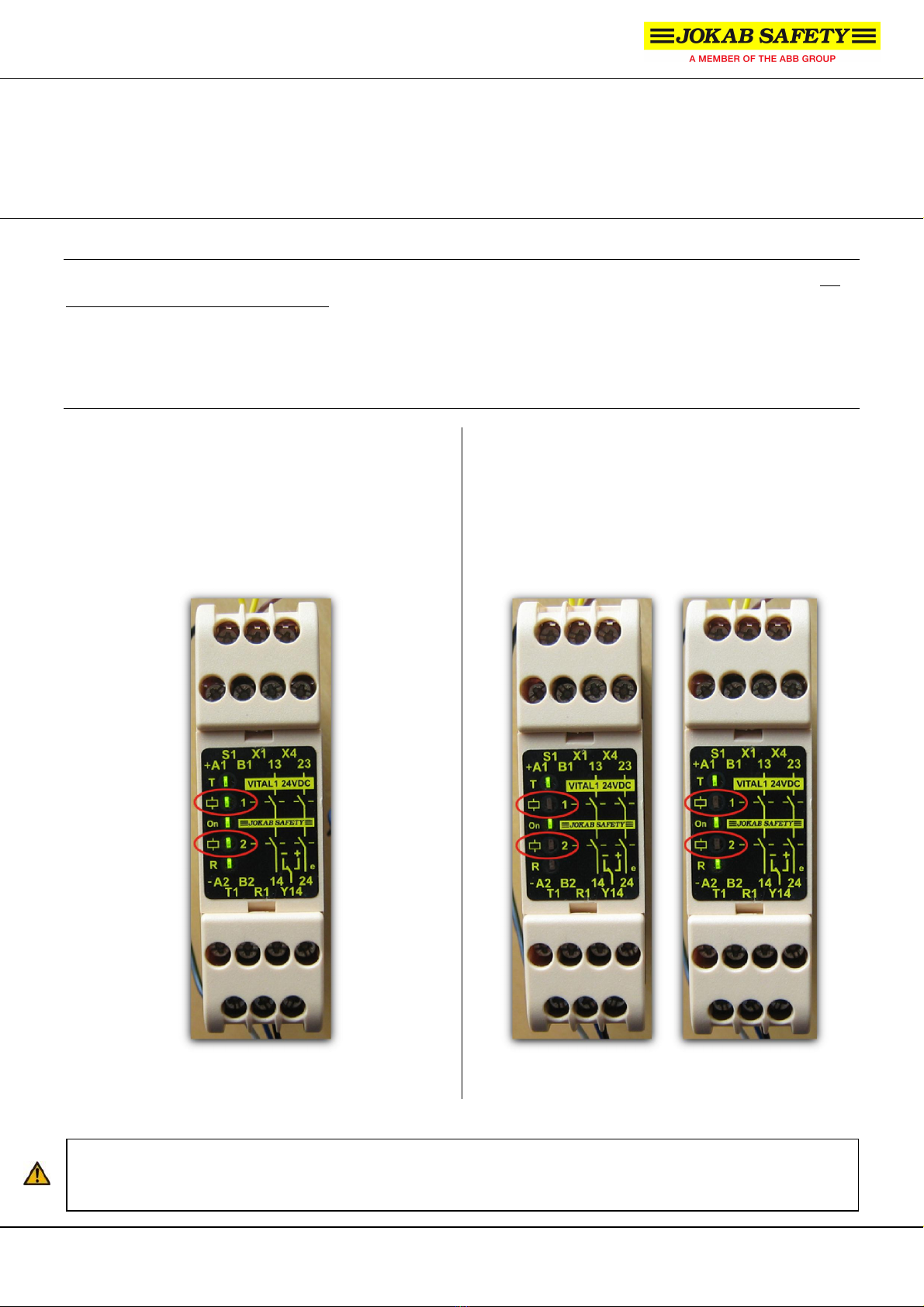
functionality is indicated by the LEDs on the front panel of Vital 1. Specifically, LEDs #2 and #4 (marked with red
circles in the pictures below) indicate the status of the safety outputs.
Instructions
1 ) When power is supplied and all safety devices
connected to Vital 1 are un-interrupted (i.e. the
safety circuit is closed), all five LEDs on the front
panel should be turned ON, as shown in the picture
below.
2 ) Interrupt any of the safety devices connected to the
Vital 1 unit. Both safety outputs should then be
deactivated. LEDs #2 and 4 indicate the status of
the safety outputs and should now be turned OFF.
The state of the LEDs should be the same as either
of the two pictures below.
In this state, the machine/process is allowed to start. In this state, the machine/process is stopped by Vital 1.
If either LED #2 or LED #4 is still turned ON when the safety circuit is interrupted, the safety outputs are not
functioning properly and the unit may not be put back into operation.