manuals.online logo
Brands
  1. Home
  2. •
  3. Brands
  4. •
  5. JOMAR
  6. •
  7. Control Unit
  8. •
  9. JOMAR Add-A-Valve User manual

JOMAR Add-A-Valve User manual

® ®
Add-A-Valve®
Installation
Instructions
Central Office & Distribution Center
7243 Miller Drive
Warren, MI 48092
Phone: 800-325-5690
Fax: 800-628-4194
www.jomar.com
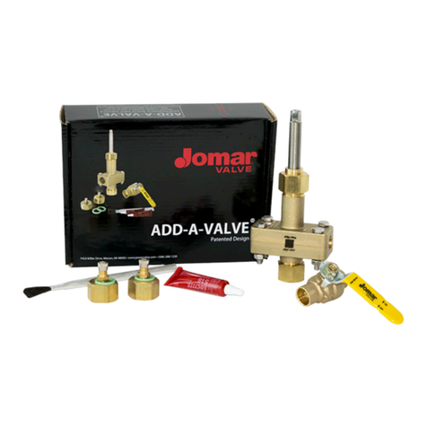
Check to be sure you have received all the parts pictured and listed below:
• Add-A-Valve®
• Jomar S-100NE
• Gasket Sealant
• Brushes (2)
• Extra Viton® O-Rings
• Shraeder® test caps (2)
• Add-A-Valve® Installation CD
/ Video
Tools needed:
• Needle-nose pliers
• Flat head screwdriver
• Hammer
• Adjustable wrench
• Ratchet wrench
• Open end wrench
• Emery cloth
Before you start:
On multi-story buildings - all pumps, main
and circulator, must be shut down prior to
installation.
On a closed system, you must install TWO Add-
A-Valves® to isolate the problem area.
ATTENTION:
Jomar requires that the Add-A-Valve® installer
view the Jomar installation CD / Video prior to
attempting installation. Failure to do so will
relinquish Jomar from any and all liability for
improperly installing an Add-A-Valve® device.
In this case, Jomar will not be responsible,
nor will it exchange or provide a refund for any
improperly installed Add-A-Valve®.
Copies are available for viewing on the Jomar
website at: www.jomar.com and upon request.
To assist with installation, check off each step as you complete it
Step 1
Before installing the Add-A-Valve®, clean the copper tubing with a fine emery
cloth to a bright shiny finish.
Step 2
Disassemble the Add-A-Valve® body by removing the four (4) 316 stainless
steel bolts.
Step 3
You will be supplied two small tubes of gasket sealant. One tube per body half.
Apply a liberal amount of gasket sealant and brush evenly across the entire body
half surface.
Do this to both body halves and allow 1-2 minutes for dry time.
To ensure proper step order, follow the page numbers > 1
2
3
® ®
For Technical Support
Monday thru Friday
8am - 6pm EST
Call 1-800-325-5690 or visit:
www.jomar.com
The Jomar Add-A-Valve® is engineered for ONE-TIME
use as an emergency shut-off device! Once the stem
cutter has been raised DO NOT lower it again.
Step 4
Note: Be sure the stem cutter is backed out all the way so that the cutter does
not make contact with the copper tubing.
Assemble the two body halves around the copper tubing and replace the four (4)
316 stainless steel bolts.
Step 5
Using a ratchet and wrench, tighten the four bolts in an ‘X’ pattern to a torque of
95 - 105 in/lb. Be careful not to overtighten, as you may strip the bolts and cause a
leak. If, after proper assembly of the four bolts, you experience a slight gap between
the two halves of the Add-A-Valve®, make sure the gap is evenly distributed on both
sides of the body. A closed gap on one side and an open gap on the other will cause
a leak. Additionally, it will prevent the cutter from making a straight cut and will
damage the pipe, thereby making it susceptible to breakage or a leak.
Step 6
To begin testing your installation, remove the stem and bottom cap and screw on
the test caps that are supplied with your kit.
Step 7
Pump air into both test caps at approximately 15-20 psi. We are testing the
installation sealant and valve bodies for leaks.
Step 8
Now spray the entire body of the valve with a soapy water solution and check for
bubbles that indicate a leak.
If you see any bubbles, reposition or tighten and then retest.
Do NOT proceed with the Add-A-Valve® installation until testing succeeds.
Step 9
When it air tests without leaks, remove both test caps and replace with the stem
cutter and bottom cap.
Note: Be sure the stem cutter is backed out all the way so that the cutter does not
make contact with the copper tubing.
We are now ready to engage the stem cutter.
Use a 3/8” socket
wrench, manual
operation only! Do
NOT use a drill
motor.
Keeping steady
pressure, ratchet
the stem cutter
down until you’ve cut through both walls of the copper
tubing.
CAUTION
Before engaging the cutter, pipe hangar supports should be installed on both sides of the Add-
A-Valve®, 12 inches on center to eliminate stress at the ends of the valve. If hangars cannot be
installed, it is NOT recommended to use the Add-A-Valve®.
CAUTION
Pipe hangar supports should be installed on both sides of the Add-A-Valve®, 12 inches on
center to eliminate stress at the ends of the valve. If hangars cannot be installed, it is NOT
recommended to use the Add-A-Valve®.
Step 11
You must now remove both copper slugs and flush the debris. Begin by removing
the bottom cap. There may be some water trapped here. However, if water does
not appear to be completely shut off, remove the bottom cap completely and slowly
ratchet the stem cutter down further until water flow stops.
To remove slugs, take a hammer and a flat head screwdriver and gently tap the high
side of the two copper slugs into a vertical position and remove with needle nose
pliers.
Note: To flush debris, reverse the stem cutter with bottom cap off until you see a
flow of water. Debris should be flushed. Reseat the valve until the flow stops and
replace cap. Congratulations, shut down is now complete! You can now use the
Add-A-Valve® to make a repair or as a live, hot tap. The Jomar Add-A-Valve®
is engineered for ONE-TIME use as an emergency shut-off device!
Once the stem cutter has been raised DO NOT lower it again.
4 5
This is a TWO
person operation.
Use a 9/16” socket
wrench on the stem
cutter, and with the
help of a second
person, use an
open end wrench
on the outer stem.
This sets the depth of the cut and prevents the cutter
from binding. Slowly turn both wrenches at the same
time.
SINGLE STEM
For sizes 1/2” to 1”
DOUBLE STEM
For sizes 1-1/4” to 2”
Step 10
When you’ve reached the stop ring, you’ve reached the seating position of the valve. At this
time, ratchet one to one and a half turns to expand the Viton® seal across the two pipe cuts.
Determine what size Add-A-Valve® you have and follow the corresponding directions

Other JOMAR Control Unit manuals

JOMAR FL-CS-100-150 User manual

JOMAR

JOMAR FL-CS-100-150 User manual

JOMAR Add-A-Valve User manual

JOMAR

JOMAR Add-A-Valve User manual

Popular Control Unit manuals by other brands

Danfoss AMZ 112 installation guide

Danfoss

Danfoss AMZ 112 installation guide

Asco 8316 Series operating manual

Asco

Asco 8316 Series operating manual

Burkert 265X instruction manual

Burkert

Burkert 265X instruction manual

EA SV Series Original operating manual

EA

EA SV Series Original operating manual

Zte ME3000 user manual

Zte

Zte ME3000 user manual

ProSoft Technology MVI69-GEC user manual

ProSoft Technology

ProSoft Technology MVI69-GEC user manual

Grundfos BM Installation and operating instructions

Grundfos

Grundfos BM Installation and operating instructions

Texas Instruments LMK00308EVM user guide

Texas Instruments

Texas Instruments LMK00308EVM user guide

VIA Technologies COMe-8X91 user manual

VIA Technologies

VIA Technologies COMe-8X91 user manual

Keysight VXI Bus 75000 C Series User and programming manual

Keysight

Keysight VXI Bus 75000 C Series User and programming manual

VACUVENT VA Series owner's manual

VACUVENT

VACUVENT VA Series owner's manual

Philips VCM3110 Instructions for use

Philips

Philips VCM3110 Instructions for use

Valcom V-2003A Technical specifications

Valcom

Valcom V-2003A Technical specifications

System Sensor CR-6 Installation and Maintenance

System Sensor

System Sensor CR-6 Installation and Maintenance

Allen-Bradley PowerFlex 755 user manual

Allen-Bradley

Allen-Bradley PowerFlex 755 user manual

Schell 03 284 00 99 Assembly instructions

Schell

Schell 03 284 00 99 Assembly instructions

EKE-Electronics EKE-Trainnet MVB2791B Technical manual

EKE-Electronics

EKE-Electronics EKE-Trainnet MVB2791B Technical manual

Lincoln 3866 manual

Lincoln

Lincoln 3866 manual

manuals.online logo
manuals.online logoBrands
  • About & Mission
  • Contact us
  • Privacy Policy
  • Terms and Conditions

Copyright 2025 Manuals.Online. All Rights Reserved.