JOMAR FL-CS-100-150 User manual

061920 © 2020 Jomar Valve • www.jomarvalve.com • P: (586) 268-1220 • F: (586) 979-8315
Note: Information subject to change without notice.
1
IO&M Guide
FL-CS-100-150 & FL-SS-100-150, FL-CS-100-300 & FL-SS-100-300
1. Before Installation
1.1 Fluid thermal expansion:
Pressure, built-up in the body cavity by
heating volatile uid, can damage the
seats or the ball. The hole in the ball beneath
the stem slot will equalize pressure between
body cavity and the pipeline when valve is in
the open position.
1.2 Anti-Static device:
Jomar’s Flange Series ball valves are provided
with anti-static devices for ball-stem-body.
When service conditions require electrical
continuity to prevent static discharge, the user
is responsible for specifying static grounding.
1.3 Throttling service:
Ball valves are generally not recommended for
throttling service, where both the uid ow
and the leading edge of the ball can damage
or deform the resilient ball seats causing
leakage. High uid velocity or the presence
of solid particles in suspension will further
reduce seat life. These valves are not intended
to be operated in a partially open position.
1.4 Do not open the bonnet or cap when
valve is under pressure. Valve is not equipped
with pressure access device.
1.5 Do not touch the surface of the valve
on high temperature applications.
1.6 Not suitable for unstable uid.
1.7 Locking device on the handle to avoid
unauthorized operation is optional.
2. Installation and Operation
2.1 Handling
During installation, larger valves require a
hoist to lift both sides of the body.
2.2 Cleaning
Even if valves were transported in a clean
environment, installers must check for any
foreign body or dust inside the bore. If any,
clean thoroughly before installation. Installers
to clean valves with water, compressed air, or
steam (automated valves should be cleaned
only with water or steam, compressed air is not
allowed.) For cleaning, rst step is to stand the
valve with bore perpendicular to the ground and
clean, ensuring all foreign matter is removed
from the bore. Then check and clean the
connecting pipe bores and ange faces.
2.3 Valve Installation
a. Direction
Ball valves are normally bi-directional, i.e. no
preferred ow direction.
b. Position
The valves weight bearing ability and
gradient are very important to the pipe
installation. Do not allow the pipeline stress
to be transmitted to valve anges and cap. It
could cause body deformation and seat leakage.
c. Bolt tightening of anged ends. The force
must be evenly spread. Tightening order for
anged ends is given below.
2.4 Operation
a. For manual operation, turn the lever in
counter clockwise to close and clockwise to
open. If the handle is parallel to the pipeline, the

061920 © 2020 Jomar Valve • www.jomarvalve.com • P: (586) 268-1220 • F: (586) 979-8315
Note: Information subject to change without notice.
2
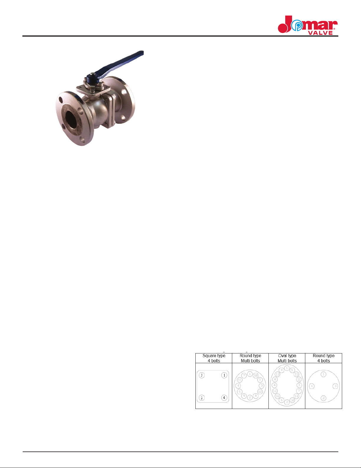
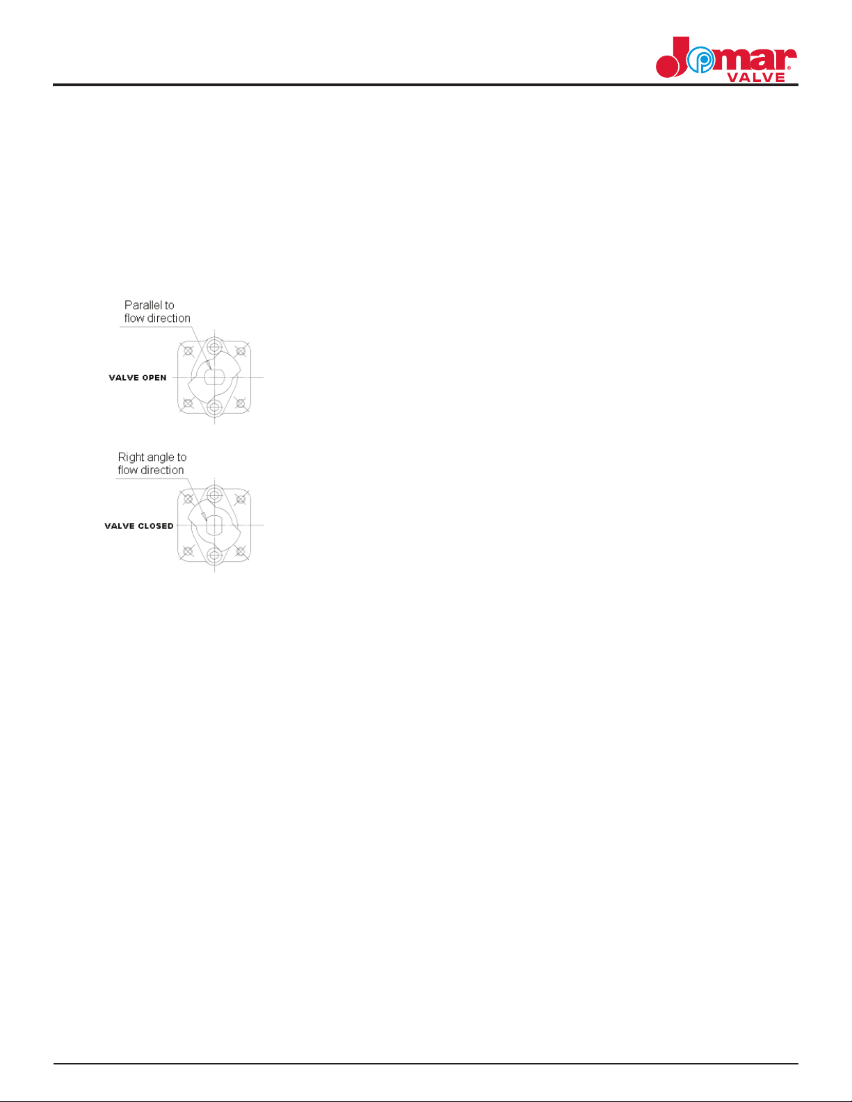
valve is open. If the handle is at right angles
to the pipeline, the valve is closed.
b. When the valve is operated with
removable handle, the user should ensure the
position of the valve, whether open or closed.
There is a mark at the top of stem for double
“D” type stem. Refer Fig 1 below showing how
to determine the valve’s position.
Fig-1
3. Maintenance
3.1 Maintenance frequency
The maintenance frequency is determined
by the valve’s application. User shall consider
the time interval depending on uid, ow
velocity, operational frequency, high-pressure
eect and high-temperature eect etc. Valves
should be operated at a minimum twice a
year.
3.2 Disassembly
a. To disassemble the valve, please follow
the procedure and drawings below.
1) Turn the valve fully open. Loosen No.
16-1 and 18, remove No. 14 handle and
No. 15 at washer.
2) Use pincer to take o snap ring. Turn
ball until half open. Remove No. 12 stop
plate.
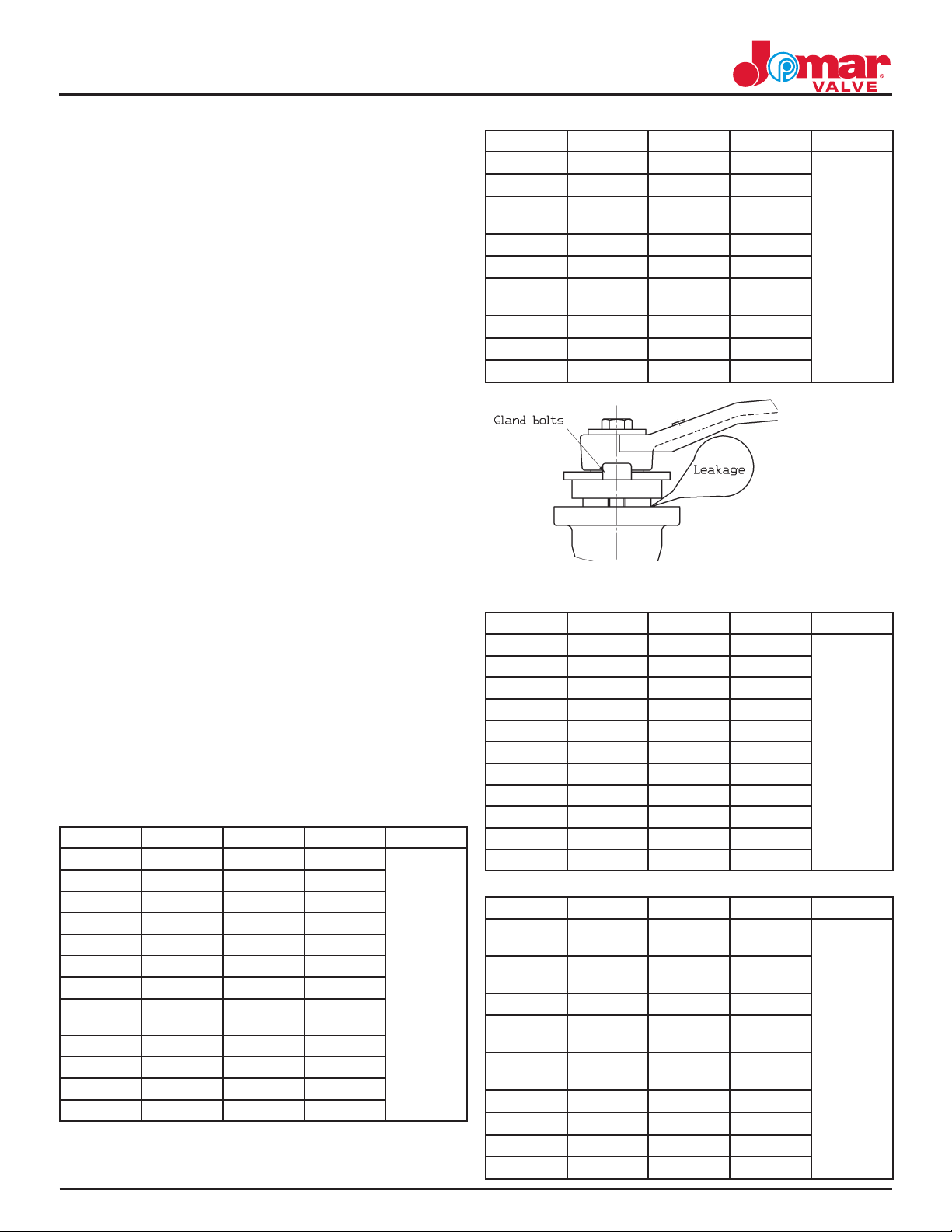
3) Remove No. 11-1 gland bolts., remove
No. 10 gland ange.
4) Remove No. 17 Bolts using a ring
spanner. Remove No. 2 cap.
5) Take No. 6 body seal and No. 3-2 seat
out. Fully close ball and remove No. 4
ball and 3-1 seat.
6) Take No. 5 stem out by pushing No.
5 stem downward. Remove No. 8 stem
packing and No. 7 thrust washer.
7) Do not remove No. 19 & No. 20. Static
devices.
b. It is necessary to open the ball slightly
to drain the body cavity slowly. Be aware of
media trapped in the body cavity and take
necessary precautions for safe handling and
protect against exposure.
c. The ball cannot be taken out from valve
body if the ball is in the open or semi-open
position. The correct position to work on the
valve is with the ange end down.
d. To separate the valve body and cap,
undo the bolts symmetrically.
e. During and after assembly/disassembly,
take precaution not to damage the surface of
the ball.
3.3 Parts inspection, maintenance, and
replacement:
a. Check the surface of ball for marks.
If there is any damage on the surface, nd
out the root cause such as dirt, uid…etc. It
is important to avoid these damage factors
wherever possible.
b. If the ball surface is damaged at the
contact area of ball and ball seat the ball must
be re-surfaced. If it is damaged heavily, and
cannot be repaired, a new ball must be tted.
c. Inspect the surface of soft seats, and
replace if any damage or deformation is
evident.
d. The stem seal must be replaced after
disassembling the valve.
e. Repair kits are available by contacting
Jomar.

061920 © 2020 Jomar Valve • www.jomarvalve.com • P: (586) 268-1220 • F: (586) 979-8315
Note: Information subject to change without notice.
3
3.4 Assembly
The assembly process, is opposite to the
disassembly process. The ball must be at the
closed position when assembling the body
and end cap. The stop plate must be correctly
positioned on the stem otherwise, the open
and close operation will be reversed.
Final inspection of repaired valve. It is
necessary to operate the valve open and
closed to ensure all the parts are assembled
correctly. Be sure the torque is the same
during the open/close operation. If the
torque is not the same during operation, it
may have some parts positioned incorrectly or
be experiencing interference. If this happens,
it must be disassembled and re-assembled.
The valve will be damaged if it is placed back
in the pipeline while wrongly assembled and
may be a safety hazard.
3.5 Tightening torque of gland bolts
Gland bolts can loosen after the valve is in
use over a period of time, and cause leakage.
It is necessary to check the gland bolts
periodically. If the bolts are loose, tighten
according to torque data given below.
4. Torque Data
PACKING GLAND
FL-CS-100-150 & FL-SS-100-150
SIZE Bolt Size N-m (kgf-cm) Tolerance
1/2” 1/4”-20UNC 2 20
+/- 10%
3/4” 1/4”-20UNC 2 20
1” 5/16”-18UNC 4 40
1-1/4” 5/16”-18UNC 4 40
1-1/2” 3/8”-16UNC 10 100
2” 3/8”-16UNC 10 100
2-1/2” 3/8”-16UNC 10 100
3” W1/2”-
12UNC
20 200
4” 5/8”-11UNC 30 300
5” 5/8”-11UNC 30 300
6” 5/8”-11UNC 30 300
8” 5/8”-11UNC 30 300
FL-CS-100-300 & FL-SS-100-300
SIZE Bolt Size N-m (kgf-cm) Tolerance
1/2” 1/4”-20UNC 2 20
+/- 10%
3/4” 1/4”-20UNC 2 20
1” 5/16”-
18UNC
4 40
1-1/2” 3/8”-16UNC 10 100
2” 3/8”-16UNC 10 100
3” W1/2”-
12UNC
20 200
4” 5/8”-11UNC 30 300
5” 5/8”-11UNC 30 300
6” 5/8”-11UNC 30 300
BODY BOLTS
FL-CS-100-150 & FL-SS-100-150
SIZE Bolt Size N-m (kgf-cm) Tolerance
1/2” 5/16”-18UNC 25 250
+/- 10%
3/4” 5/16”-18UNC 25 250
1” 3/8”-16UNC 40 400
1-1/4” 3/8”-16UNC 40 400
1-1/2” 7/16”-14UNC 45 450
2” 7/16”-14UNC 45 450
2-1/2” 7/16”-14UNC 45 450
3” 1/2”-13UNC 75 750
4” 1/2”-13UNC 75 750
6” 5/8”-11UNC 182 1850
8” 3/4”-10UNC 350 3500
FL-CS-100-300 & FL-SS-100-300
SIZE Bolt Size N-m (kgf-cm) Tolerance
1/2” 5/16”-
18UNC
25 400
+/- 10%
3/4” 5/16”-
18UNC
25 400
1” 3/8”-16UNC 40 400
1-1/2” 7/16”-
14UNC
45 450
2” 7/16”-
14UNC
45 450
3” 1/2”-13UNC 75 750
4” 5/8”-11UNC 182 1850
5” 3/4”-10UNC 350 3500
6” 1”-8UNC 569 5800
This manual suits for next models
3
Other JOMAR Control Unit manuals
Popular Control Unit manuals by other brands

Delta
Delta Hikvision DS-2FP2020 user manual

PRO-TEK
PRO-TEK UDM-001 Operator's installation and instruction manual

Heath Zenith
Heath Zenith CB-2011 user manual

Mark
Mark 3002866 Technical manual

Blue Technix
Blue Technix Sentis ToF-P510 Hardware user manual

Heath Zenith
Heath Zenith DualBrite Motion Sensor Light Control 5797 owner's manual