3
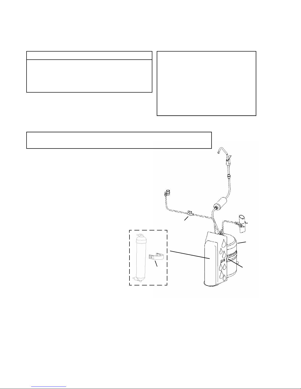
For cartridge replacement, call your local distributor or 1-888-856-6322
For USA and Canada Only The Limited Warranty extends to the original purchaser of the system. This warranty
covers all parts and factory labor needed to repair any Manufacturer-supplied item that proves to be defective in
material, workmanship or factory preparation. The above-mentioned warranty applies for the first full calender year
from date of purchase. These defective items are subject to the following exclusions: membranes, filters, O-rings,
and all other parts or components that require regular replacement as a result of ordinary usage.
Disclaimers This Warranty applies only if the system is installed and used in compliance with the instructions
enclosed with the system.
This Warranty does not cover the costs of repairs or adjustments to the unit that may be needed because of the use
of improper parts, equipment or materials. This Warranty does not cover repairs required due to unauthorized
alterations of the unit, or failure of a unit caused by such alterations or by unauthorized repairs.
The Warranty does not cover malfunctions of the unit due to tampering, misuse, alteration, lack of regular
maintenance, misapplication, fouling due to hydrogen sulfide or iron, scaling from excessive hardness, turbidity
greater than 1.0 NTU, Silt Density Index (SDI) greater than 5.0 SDI, or excessive membrane hydrolysis due to chlorine
levels in excess of 0.5 ppm. In addition, damage to the unit due to fire, accident, negligence, act of God, or events
beyond the control of the Manufacturer are not covered by this warranty.
Incidental and Consequential Damages The Manufacturer does not assume responsibility for payment of
incidental and consequential damages as a result of the failure of this unit to comply with express or implied
warranties, such as lost time, inconvenience, damage to personal property, loss of revenue, commercial losses,
postage, travel, telephone expenditures, or other losses of this nature. Some states do not allow the exclusion or
limitation of incidental or consequential damages, so this exclusion may not apply to you.
Owner’s Warranty Responsibilities Under the provisions of the Warranty, the owner is expected to schedule
maintenance, as described in this Manual. Neglect, improper maintenance, abuse, or unapproved modifications may
invalidate the Warranty. Should your unit develop a defect or otherwise fail to perform in accordance with this
warranty, you should contact the dealer from whom the product was originally purchased.
Implied Warranties The implied at-law warranties of merchantability and fitness for a particular purpose shall
terminate on the date one year after the date of purchase. Note: some states do not allow limitations on how long
an implied warranty lasts, so the above limitations may not apply to you.
Other Rights This Warranty gives you specific legal rights and you may also have other rights which vary from state
to state.
C
Precision RO - Warranty