Jonsered 6000+ User manual

Read through this manual carefully and make
sure that you have understood the contents
before you use the one-man sawmill.
Operator's manual

2English
Introduction .......................................3
Symbols .............................................4
Warning markings .............................4
Safety instructions ............................5
Descriptions.......................................8
Installation .......................................18
Fuelling ............................................23
Starting and stopping .....................25
General use......................................26
Maintenance.....................................30
Technical particulars.......................45
CONTENTS

3
English
This instruction manual describes in detail how to
use and service the one-man sawmill and how
periodic checks are to be carried out. It also de-
scribes what measures should be taken to
ensure maximum safety, how the safety devices
are de-signed, how they function, how to check
and examine them, and carry out repairs, if
required.
CAUTION! The section concerning safety
must be read and understood by everyone
who installs, uses and repairs the sawmill.
The instruction manual covers the installation,
the general use and the various maintenance
meas-ures to be carried out by the user. If more
thorough service or fault tracing is required, this
must be carried out by qualified service
personnel. For particulars, get in touch with your
local dealer.
The instruction manual contains a description of
all the necessary safety devices. This description
must be read and understood by the user before
assembling the sawmill. In other words, the first
measure to be taken after the unit is delivered, is
to find and read the instruction manual.
Introduction
The symbols and warning markings on the one-
man sawmill are illustrated on the next page of
this instruction manual. If any warning decal has
become disfigured or worn, a new one must be
ordered at once and fitted to the unit as soon as
possible. This will ensure best possible safety
when using the one-man sawmill.
The one-man sawmill should only be used for
sawing boards and planks from logs.
INTRODUCTION

4English
Symbols Warning markings
The symbols illustrated below appear in this
user's manual. These symbols indicate the
appropriate equipment that must be used for
each application, and are as follows:
Eye and ear protection must be
used.
Boots or work shoes with steel toe
cap and non-slip soles must
be used.
Protective eye glasses must be
used.
Protective gloves must be used.
Checks and/or maintenance must
be carried out with the motor de-
energised, i.e. with the shut-down
switch in the "STOP" position.
The one-man sawmill has decals with the
symbols illustrated below. The first three symbols
indicate the equipment that must be worn when
sawing, and are as follows:
Boots or work shoes with
steel toe caps and non-
slip soles must be used.
Eye and ear protection
must be used.
Read through this
instruc-tion manual
carefully and make sure
that you have
understood the contents
before you use the one-
man sawmill.
Exercise the greatest
caution!
Hot sur-
face.
Do not run the unit unless
the safety guards are
intact and you are
wearing saftety gear.
Protective gloves must
be used.
SYMBOLS USED

5
English
!WARNING!
If the one-man sawmill is used
improperly or in a careless
manner, it may become a
dangerous tool, which can
cause serious, even grave,
injury. It is therefore vital, that
the persons, who will be using
the one-man sawmill, read and
understand the contents of this
manual.
Safety instructions
SAFETY INSTRUCTIONS
Personal protective equipment
The user(s) of the one-man sawmill or those
spending time in the immediate viscinity of the
sawmill must wear safety equipment of the type
illustrated below:
1. Ear protection.
2. Eye protection.
3. Approved gloves with protection against saw
cuts.
4. Boots or work shoes with steel toe cap and
non-slip soles.
5. First aid kit.
!WARNING!
Provide sufficient ventilation.
Exhaust gases and sawdust
can be harmful and cause
allergies.

6English
!WARNING!
Theone-mansawmillmustnever
beusedifanyofthesafetydevices
or guards are missing, damaged
or out of function.
The sawmill is equipped with a number of safety
devicesandguardsdesigned to prevent accidents
from occurring when using the sawmill. These are
described under the general description of the
sawmill. See pages 14-15.
Thesafetydevicesandguardsalsorequireregular
checks and maintenance. These measures and
theintervallsatwhichthey aretobecarriedoutare
given under "Maintenance". See pages 30-44.
Safety when handling fuel
!WARNING!
The fuel used in the one-man
sawmill has the following
harzardous properties:
1. Liquid fuel emits poisonous gas
fumes and exhaust gases.
2. Can cause skin irritation.
3. Is extremely flammable.
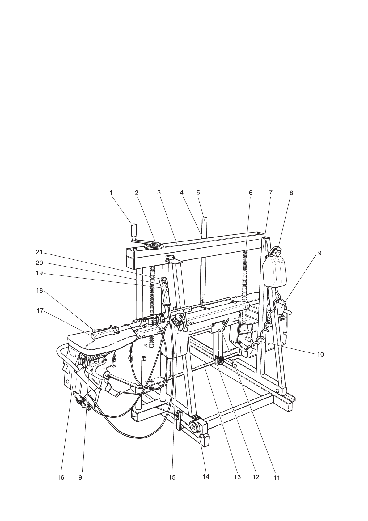
The safety equipment of the one-
man sawmill Safety during operation
Thesafetyinstructionsthatapplywhenrunningthe
one-man sawmill are given where appropriate in
the section "General use" on pages 26-29.
Before and while using the sawmill, the operator
must observe the following safety precautions:
1. Checkthatallofthesafetydevicesandguards
are in place and are faultless.
2. Check that no fuel has been spilled outside
the tank or on the ground.
3. See to it that no unauthorised persons enter
the risk zone of the one-man sawmill.
4. Thestopsandthelockingdevicesrequiredfor
securing the log must be used in the intended
manner. See pages 27-29.
5. Adjust the blade guide so that it will be as
near to the log as possible. See page 27.
Specialsafetyregulationsapplytohandlingthefuel
used for running the one-man sawmill. These are
specified under "Fuelling" on pages 23-24.
5 m
3 m
3 m 3 m
SAFETY INSTRUCTIONS
Risk zone
The risk zone is shown in the figure to the right.
No unauthorised persons may be present within
the risk zone.
The risk zone must also be kept free of foreign
objects and the ground within the risk zone must
be even to prevent stumbling.
Users
The following applies to persons who use one-
man sawmill:
1. The user must have read and understood the
content of this user's manual.
2. The user must not be under the influence of
alcohol, medicin or be affected by fatigue.
3. Must be an adult.

7
English
Grinding device
The following safety instructions are applicable to
the grinding device:
• Never store petrol in the viscinity of the
griding device. Sparks from the grinding
disc or the mains electrical connection can
ignite petrol fumes.
• The saw blade has sharp cutting surfaces.
Be careful to avoid injury. Always wear
protective gloves while handling the saw
blade!
• The grinding disc must not be running while
adjustments are being made on the grinding
device.
• If the grinding disc rotates in the wrong
direction, it may come off and cause personal
injury.
• Check that the grinding disc does not have
any cracks and that it is secured on the shaft.
Stop the grinding disc immediately if
abnormal vibrations arise.
• Use protective eye glasses while grinding!
SAFETY INSTRUCTIONS

8English
DESCRIPTION
The one-man sawmill consists of two main
sections:
• Carriage with motor and saw
• Rails
In addition, the band saw is equipped with the
necessary safety devices.
1. Crank for height adjustment
2. Pitch disc
3. Chain guard
4. Pointer
5. Scale
6. Height adjustment rod
7. Stand
8. Cleaning liquid tank (saw blade cleaning)
9. Exhaust systemwith muffler
10. Blade lubrication valve
11. Locking device for moveable blade guide
12. Moveable blade guide
13. Saw blade
14. Rail guard
15. Fueltank
16. Motor
17. Steering handle
18. Brake handle
19. Throttle stop
20. Throttle control
21. Stop control (emergency stop)
22. Guide rod
23. Decompression valve
24. Starter handle
25. Blade wheel guard
26. Rail
27. Saw blade guard
28. Blade wheel
29. Scraper
30. Exhaust pipe guard
31. Adjusting of the blade wheel
32. Crank for band tensioning

9
English
DESCRIPTION
33. Socket spanner
34. Spark plug spanner
35. Combination spanner
36. Allen key 4 mm
37. Allen key 5 mm
38. Screw driver
39. This operator´s manual
40. Fixed section
41. Forward feed device
42. Grinding motor
43. Adjusting knob for forward feed position
44. Starting switch for forward feed device
45. Starting switch for grinding disc
46. Adjusting knob (grinding depth)
47. Locking knob (side plate angle)
48. Pin for locking the side plate angle
49. Setting tongs

10 English
Carriage
The carriage consists of the following parts:
• Steel construction on wheels running on rails
and guide bars for raising and lowering the
saw.
• Two threaded rods for adjusting the height of
the saw. The rods are united by a chain and
are controlled by a crank equipped with a
pitch disc.
• Handle with controls
• Saw unit with the following components:
• • Motor.
• • Adjustable saw blade wheel.
• • Saw blade.
• • Moveable blade guide for optimal blade
control.
• • Petrol tank for petrol mixed with oil.
See "Handling fuel".
• • Tank for cleaning liquid for the saw blade.
• • Muffler.
DESCRIPTION
16
5
Stand (7)
The carriage stand consists of square tubes
welded together and equipped with necessary
corner reinforcements which ensure stability
while sawing.
The stand is equipped with two round guide rods
for the upward and downward movement of the
saw. The guides transfer the transverse forces of
the saw to the stand.
The lower section of the stand has four groove-
rimmed wheels journalled in bearings for stability
and even movement along the rail.
To prevent the carriage from lifting off the rails, it
is equipped with two adjustable guide wheels
(bearings), which run along the underside of the
rails.
Height adjustment
The saw unit is stabilised vertically by two
interacting threaded rods (6). The threaded rods
are united by a chain for exact and simultaneous
movement.
A crank (1) is located on the top end of one of
the rods, and is used to set the exact lumber
thickness.
One turn of the crank moves the saw blade 5
mm. The saw blade height over the rail cross
beams can be read on the scale (5).

11
English
Steering handle (17)
The saw carriage can be controlled and steered
forward by means of the steering handle located
on the left-hand section of the carriage.
The steering handle is equipped with the
following controls:
18 Brake handle
19 Throttle stop
20 Throttle control
21 Stop control (emergency stop)
Saw blade wheel (28)
The saw blade runs across blade wheels, made
of cast aluminium and balanced for smooth
running. The saw blade wheels have bearings,
and are adjustable for tensioning and aligning
the saw blade.
The saw blade wheels are equipped with
scrapers, which prevent sawdust and the like
from collecting between the saw blade and the
blade wheels.
One of the saw blade wheels is driven across an
adjustable drive belt by the motor.
Saw blade (13) and blade guide
(12)
Two saw blade guides keep the saw blade
correctly positioned on the saw blade wheels
while the saw is in operation.
One of the saw blade guides is located in front of
the belt-driven saw blade wheel and ensures
correct blade entry onto the wheel.
The other saw blade guide is moveable and is
located above the the blade before it enters the
log. This guide absorbs the forces from the log
and prevents the blade from twisting.
DESCRIPTION
21
20
19
18 17
12 13 28
28

12 English
Motor (16)
The one-man sawmill is driven by an air-cooled,
two-stroke motor of the type previously and also
currently used in our larger chain saws. The
motor is equipped with a centrifugal coupling,
which causes the saw blade to stop when the
motor is idling.
Whenever sawing is in progress, the motor
should be run at full capacity (with the throttle
fully open).
The carburetor of the motor is adjustable for
operation either under normal weather conditions
or under cold weather conditions, see under
"Winter operation" on page 33.
Tanks (8, 15)
The saw carriage is equipped with two tanks.
The fuel tank (15) is located beneath the right-
hand steering handle
The cleaning liquid tank (8) is located on the
right-hand side of the saw carriage and supplies
cleaning liquid to the saw blade everytime the
brake handle is activated.
DESCRIPTION
15 8
Exhaust system (9)
The exhaust gases from the motor are
discharged away from the operator through the
exhaust pipe and muffler.

13
English
DESCRIPTION
Log lifter (A)
The log lifter is designed for raising the smaller
end of the log, so that the heartwood will be
horizontal.
Log locking device (C)
The log locking device consists of an eccentric
link with handle, journalled in a moveable unit.
The locking device is used for securing the log
against the folding stops.
ABC
Rail assembly
The rail assembly consists of two sections
(standard supply). Each section is 3 m long. The
sections are to be arranged in-line and screwed
together to form a track for the carriage. The rail
sections are screwed together and anchored by
M 12-screws with nuts. Thish ensures stable and
linear carriage movement.
The rails also have a number of supporting
cross-beams, which are designed to provide
stable support for the log, which is to be sawn
into planks or for planks, which are to be trim-
med.
The rail cross-beams are equipped with:
• folding stops for the log
• Log locking device
• Log lifter for one end of the log
The rail assembly is also equipped with stops at
both ends for the saw carriage and specially
adjusted transition pieces at its joints.
Folding stop (B)
On the left side of the rails, there are a number of
folding stops for holding the log in place. For
enhanced versatility, the stops of two lengths are
provided.

14 English
DESCRIPTION
The one-man sawmill is equipped with a number
of safety devices, which are described under the
coming headings.
Saw blade wheel guard (25)
The saw blade wheels are fitted with a guard (a
plastic cowl), one fitted at each wheel. Each
plastic cowl is secured by 3 rubber staps which
facilitate removal and refitting whenever the saw
blade has to be replaced.
Safety devices
Saw blade guard (upper) (A)
The upper section of the saw blade runs in a slot.
The slot is permanently secured to the saw unit.
Saw blade guard (lower) (27)
The section of the saw blade that is not covered
by the log during the sawing operation is
equipped with a guard, which is mounted on the
saw blade guide and is moveable on it.
Brake (B)
To enable the saw blade to quickly come to a
stop when the brake handle and the throttle are
released, the unit has an automatic brake which
influences the left-hand saw blade wheel.
A
25
27
B
!WARNING!
The one-man sawmill must not
be started up if any safety
device has been removed, is
defective or is out of function.
Exhaust pipe guard (30)
The exhaust pipe is equipped with a guard which
prevents the operator from coming in contact
with its hot surface.
30 9
Muffler (9)
The saw is equipped with an exhaust pipe and a
muffler which reduce noise emitted from the
motor and discharge exhaust gases away from
the oper-ator.

15
English
DESCRIPTION
Rail stops
Rail guards (14)
21
A
14
3
The rails have two rail stops (A) at each end. The
stops consist of bolts secured in the rails.
The saw carriage is equipped with four rail
guards which run over the rail. The rail guards
are de-signed to keep the rail clean and prevent
squeeze injuries between wheel and rail.
Stop control (21)
A stop control is fitted on the right-hand handle.
This control also functions as an emergency
stopping device.
Chain guard (3)
The chain which unites the two threaded height-
adjustment rods is equipped with a guard in the
form of a plastic cowl, which is secured by two
screws.

16 English
DESCRIPTION
Grinding device
42
41
46
47
45
40
43 44
48
The grinding device consists of the following
components:
• A fixed section.
• Grinding motor.
• Forward feed device.
The fixed section contains a motor for forward
feed of the saw blade and three foldable support
arms which form a stable platform for setting up
the grinding device. The support arms also guide
the saw blade while grinding is carried out.
The section with moving parts consists of a
motor, grinding disc and arms that secure its
position. The section withmoving parts can be
adjusted for grinding three different side plate
angles: 11°, 15° and 19°.
The forward feed device consists of a cam and
levers. The cam is driven by the forward feed
motor in the fixed section. The cam influences
two levers which both feed the saw blade for-
ward and lower and raise the grinding disc during
the grinding operation.
40. Fixed section.
41. Forward feed device.
42. Grinding motor.
43. Adjusting knob for forward feed position.
44. Starting switch for forward feed device.
45. Starting switch for grinding disc.
46. Adjusting knob (grinding depth).
47. Locking knob (side plate angle).
48. Pin for locking the side plate angle.

17
English
DESCRIPTION
Setting tongs
The setting tongs are factory-adjusted to set the
saw blade teeth at 0,4-0,5 mm.

18 English
INSTALLATION
Unpacking
Unpack the one-man sawmill and check that all
of the parts have been delivered.
Check also that none of the parts are damaged.
If any parts are damaged, report this to the
shipper.
Find the instructions and read them thoroughly
before doing anything with the parts supplied.
The instructions provide thorough information
about safety, assembly, general use and
Continue as follows:
1. Adjust the supporting surface until the rails
form a straight line and rest firmly on each
wooden stud. Use a level or a length of twine
to check this.
If necessary, use adjustable feets, to position
the rails on the studs.
2. Secure the rails to one another using the
M12 screws and nuts supplied. Two screws
with nuts and four washers are needed at
every rail joint. Tighten the nuts on the
screws to a torque of 15-20 Nm.
3. Fit the two stops on the ends of the rails.
4. Apply a load on the rails over every stud by
shifting your weight on them to make sure
that they lay firmly and do not move.
15-20 Nm
Installation
Installation location
The outdoor site you choose for setting up the
oneman sawmill should have a firm, level sur-
face. Make sure that there will be sufficient space
for logs and sawn timber.
Rails
Lay the rail sections in-line after one another on
wooden cross-studs. The distance between the
wooden studs should be about 1,5 m.
Adjustable foot
Aligning the rail
Screws and nut
maintenance of the one-man saw mill.
The parts supplied are illustrated under
"Description" on pages 6 and 7.
The supply is divided upp into the following units:
1. Rail sections (quantity as ordered).
2. Split saw carriage with motor.
3. Rail guard, 4 guards
4. Saw blade.
5. Tanks with hoses.
6. Fasteners.

19
English
INSTALLATION
Setting up the saw carriage
NOTE!
Do not place the saw carriage on the
rails or any other hard surface too
hastily. This can cause permanent
damage to the saw carriage bearings.
NOTE!
Do not place the saw carriage directly
on the ground where dirt and impurities
can come in contact with the saw
carriage wheels.
Place the saw carriage onto the rails, and posi-
tion it by carrying out the following:
1. Arrange for two persons, one on each side,
to take hold of the saw carriage. Lift the saw
carriage as follows:
Right side: At the crank for band tensioning
and under the blade wheel guard.
Left side: At the motor bar and the blade
wheel guard.
2. Lift the saw carriage and lower it carefully on
the rails. The grooved rim of the wheels at
the base of the carriage must fit over and rest
on the rails.
To adjust the position of the saw
carriage
The position of the saw carriage on the rails can
be adjusted when the guide wheels and rail
guards are mounted. The purpose of the guide
wheels (bearings) is to retain the saw carriage on
the rails and to prevent it from tilting. The rail
guards are designed to keep the rails and the
saw carriage wheels free of dirt and the like.
The following parts must be mounted on the saw
carriage:
• Two guide wheels (bearings)
• Four saw carriage rail guards.
To mount them, proceed as follows:
1. Fit the guide wheel mounting bracket in
position by means of screws. Hold a 0,2 mm
thick feeler gauge between the guide wheel
and the rail.
2. Press the guide wheel upward against the
rail and tighten screws of the guide wheel
mounting bracket to secure it in position.
Tightening torque: 40-50 Nm. Then remove
the feeler gauge.
3. Repeat steps 1-2 above when fitting the
other guide wheel.
4. Fit the four rail guards over each grooved-rim
wheel.
!WARNING!
The saw carriage is heavy. Two
persons are needed to handle
it.

20 English
INSTALLATION
Cleaning liquid tank
Mount the cleaning liquid tank on the right-hand
support beam of the saw carriage and connect
spiral hose.
Fuel tank
Mount the fuel tank on the saw carriage as
follows:
1. Secure the tank by means of screws on the
left-hand support beam of the saw carriage.
2. Connect the fuel line from the tank to the
motor.
Steering handle
Mount the steering handle on the left-hand
support beam and tighten the screws to a torque
of 5 Nm.
Allow 1 mm of play at the motor throttle control.
Position the steering handle in a suitable height.
Make sure that the wires are running easily.
1 mm
5 Nm
Table of contents
Other Jonsered Saw manuals
Popular Saw manuals by other brands

Milwaukee
Milwaukee M18 FBS85 Original instructions

BN Products
BN Products BNCE-30-24V Operation & instruction manual

Pattfield Ergo Tools
Pattfield Ergo Tools PE-850SA manual

EINHELL
EINHELL TC-SM 2131 Dual Original operating instructions

Makita
Makita JR3010 instruction manual

HIKOKI
HIKOKI C 7SB3 Handling instructions

Parkside
Parkside PFS 710 B1 Operation and safety notes

balfor
balfor SHARK Series Technical manual

MK Diamond Products
MK Diamond Products MK-370 EXP Owner's manual & operating instructions

DeWalt
DeWalt DC495 Replacement instructions

Makita
Makita 2704N instruction manual

skilsaw
skilsaw SPT99T Operating/safety instructions