
Dear Customer,
Please read this instruction very carefully before using this item. You will find
important information regarding safety of your exercise bike.
Note the following precaution before assembling or operating the
machine.
1. Keep children and pets away from the bike at all times. DO NOT leave
unattended children in the same room with the machine.
2. Handicapped or disabled persons should not use the bike without the
presence of a qualified health professional or physician.
3. If you experience dizziness, nausea, chest pain, or any other abnormal
symptoms, STOP the workout at once. CONSULT A PHYSICIAN
IMMEDIATELY.
4. Before beginning training, remove everything within a radius of 2 meters
from the machine. DO NOT place any sharp objects around the bike.
5. Position the bike on a clear, level surface away from water and moisture.
Place mat under the unit to help keep the machine stable and to protect
the floor.
6. Use the bike only for its intended use as described in this manual. DO NOT
use any other accessories not recommended by the manufacturer.
7. Assemble the machine exactly as the descriptions in the instruction
manual.
8. Check all bolts and other connections before using the machine for the first
time and ensure that the trainer is in the safe condition.
9. Hold a routine inspection of the equipment. Pay special attention to
components which are the most susceptible to wear off, i.e. connecting
points and wheels. The defective components should be replaced
immediately. The safety level of this equipment can only be maintained by
doing so. Please don't use the bike until it is repaired well.
10. NEVER operate the bike if it is not functioning properly.
11. This machine can be used for only one person’s training at a time.
12. Do not use abrasive cleaning articles to clean the machine.
13. Remove drops of sweat from the machine immediately after finishing
training.
14. Always wear appropriate workout clothing when exercising. Running or
aerobic shoes are also required.
15. Before exercising, always do stretching first.
16. The power of the machine increases with increasing the speed, and the
reverse. The machine is equipped with adjustable knob, which can adjust
the resistance.


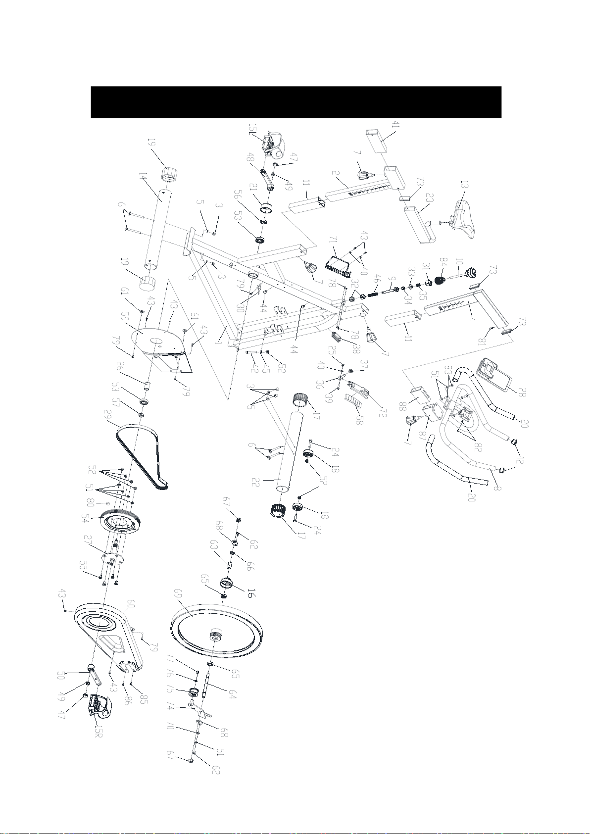


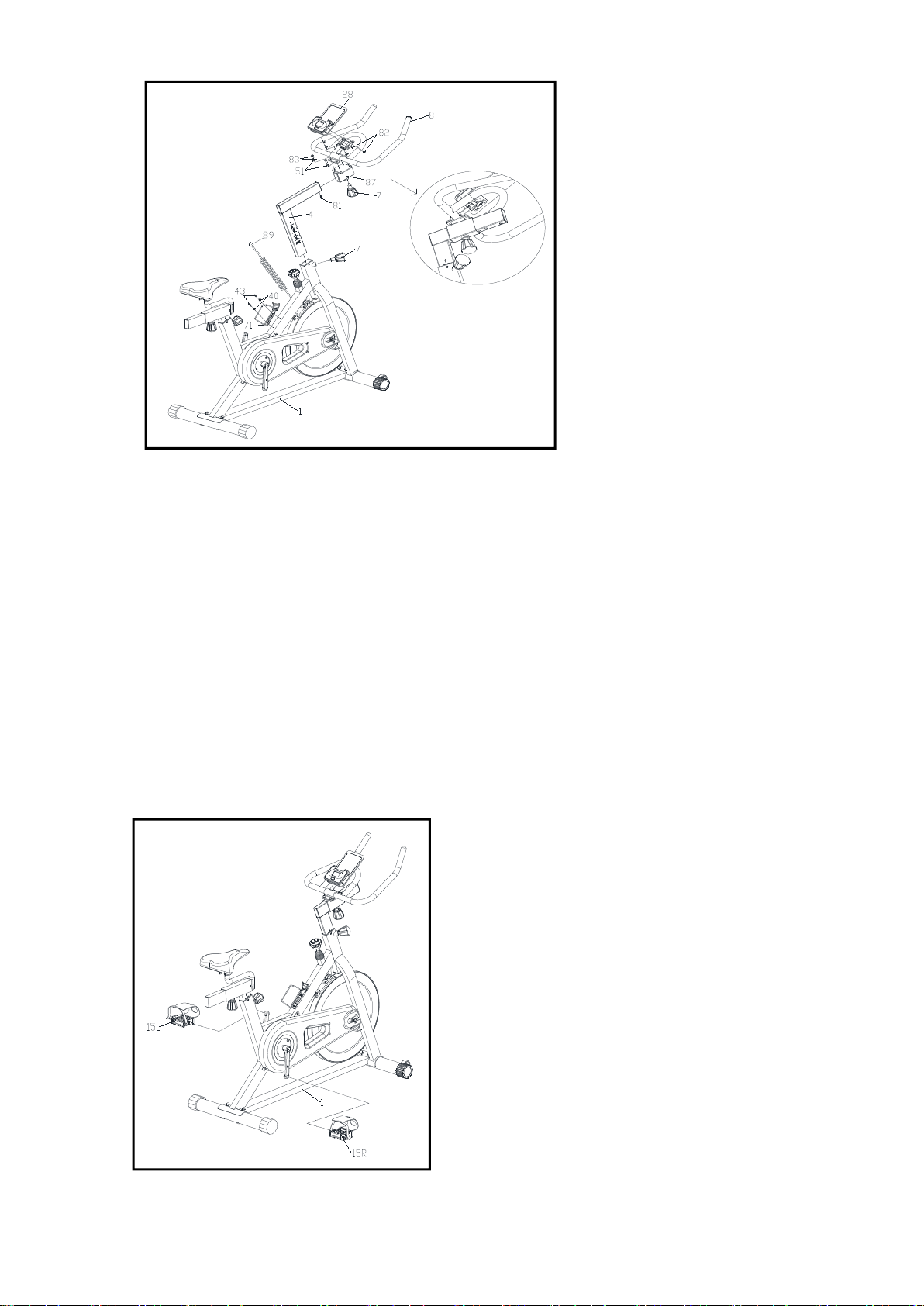


 Service manual")


