jost JB10 Series User manual

OPERATING MANUAL for
BRAKE UNITS
JB10/... JB16/... JB26/... JB40/... JB52/...
(Installation set)
JB
1 of 19
01.96/00/Scho
JB
JÖST GmbH & Co. KG
P.O. Box 1253
D - 48233 Dülmen - Buldern
Tel.: 0 25 90 / 98 - 0
Fax: 0 25 90 / 98 - 101
Telex: 89888

OPERATING MANUAL for
BRAKE UNITS
JB10/... JB16/... JB26/... JB40/... JB52/...
(Installation set)
JB
2 of 19
01.96/00/Scho
1 ELECTRICAL SAFETY
THE JB BRAKE UNIT CARRIES DANGEROUS VOLTAGE WHEN IT
IS CONNECTED TO THE MAINS.
THE JB BRAKE UNIT MUST BE EARTHED BY AN EARTH
CONDUCTOR CONNECTED TO THE PE EARTH TERMINAL OF THE
HEAT SINK.
DANGEROUS VOLTAGE MAY ALSO BE PRESENT EVEN WHEN
THE JB BRAKE UNIT IS SWITCHED OFF.
BEFORE STARTING WORK, CHECK THAT THE JB BRAKE UNIT IS
ISOLATED BY CHECKING THE CONNECTING TERMINALS WITH A
VOLTMETER.
Warning symbols
For your own safety, please pay particular attention to the
instructions marked with the following symbols:
Danger! High voltage
General warning
THE ELECTRICAL INSTALLATION
WORK MUST ONLY BE CARRIED OUT
BY AN AUTHORIZED QUALIFIED
CRAFTSMAN.
!

OPERATING MANUAL for
BRAKE UNITS
JB10/... JB16/... JB26/... JB40/... JB52/...
(Installation set)
JB
3 of 19
01.96/00/Scho
2 NOTES ON EMC LEGISLATION
The CE mark refers to Directive 72/73/EEC (93/68) on low voltage and
to [German] legislation on electromagnetic compatibility (EEC §5.2 9/92).
JB brake units are designed in accordance with standard IEC 947-4-2
for category B public mains and are within the published electro-
magnetic compatibility (EMC) limits.
The limits for emissions under the European standard do not preclude
interference with receivers within 10 m.
Installation of JB brake units must be carried out by staff trained in EMC.
The JB brake unit meets the requirements of the following standards or
equivalent documents:
1. IEC 947-4-2
2. EN 50081-2
3. EN 50082-2
JB brake units may be used only in "industry" without
further measures.

OPERATING MANUAL for
BRAKE UNITS
JB10/... JB16/... JB26/... JB40/... JB52/...
(Installation set)
JB
4 of 19
01.96/00/Scho
3 TABLE OF CONTENTS
1ELECTRICAL SAFETY.....................................................................................................................2
2NOTES ON EMC LEGISLATION .............................................................................................................3
3TABLE OF CONTENTS.............................................................................................................................4
4PREFACE.....................................................................................................................................................5
5PURPOSE.....................................................................................................................................................6
6OPERATING PRINCIPLE.........................................................................................................................6
7INSTALLATION .........................................................................................................................................7
7.1 CONSTRUCTION ....................................................................................................................................7
7.2 NOTES ON INSTALLATION..................................................................................................................7
8NOTES ON CONNECTION AND USE.....................................................................................................8
8.1 POSITION OF THE ADJ. ELEMENTS AND COMPONENTS...................................................................8
8.2 CONNECTIONS.......................................................................................................................................8
8.3 ADJUSTMENT ELEMENTS ....................................................................................................................9
8.4 MOTOR CONTROL SYSTEM AND BRAKE UNIT ................................................................................9
8.5 OVERHEATING PROTECTION(ONLY JB26/... JB40/... JB52/...)..............................................................9
9COMMISSIONING .....................................................................................................................................9
9.1 CHECKS BEFORE SWITCHING ON THE MAINS VOLTAGE..............................................................9
9.2 INTERLOCKING TEST WITHOUT BRAKING CURRENT .................................................................10
9.3 SETTING THE BRAKING CURRENT IBR..............................................................................................11
10 MAINTENANCE .......................................................................................................................................11
11 FAULT FINDING......................................................................................................................................12
12 APPENDIX .................................................................................................................................................13
12.1 TECHNICAL DATA...............................................................................................................................13
12.2 TYPE KEY..............................................................................................................................................15
12.3 DIMENSIONS.........................................................................................................................................15
12.4 LINE REACTOR - ALLOCATION /DIMENSIONS /WEIGHT .....................................................................16
12.5 CONNECTION DIAGRAMM (EXAMPLE FOR 1MOTOR)........................................................................17
12.6 CONNECTION DIAGRAMM (EXAMPLE FOR 2MOTORS)......................................................................18
12.7 CONNECTION DIAGRAMM JB10/...E000 (EXAMPLE 2MOTORS EACH WITH IN <1,5A).............19

OPERATING MANUAL for
BRAKE UNITS
JB10/... JB16/... JB26/... JB40/... JB52/...
(Installation set)
JB
5 of 19
01.96/00/Scho
4 PREFACE
The information contained in this manual refers exclusively to JB brake
units.
It is essential that you read this manual before installation and
commissioning.
The limits specified in the technical data must be observed when using
the brake unit.
The guarantee for manufacturers' drives/machinery does not cover
defects caused by misuse or incorrect use of the brake unit.
The manual is divided into individual sections in accordance with the
table of contents.
Section 1 "Electrical Safety" and Section 2 "Notes on EMC legislation"
must be read before working with the brake unit.
It is essential that the user familiarieses himself with the manual before
using the drive/equipment or before carrying out adjustment work
specific to the operations.
Please contact the manufacturer directly if you have any questions about
the JB brake unit.
The manufacturer reserves the right to make product changes without
prior notice.

OPERATING MANUAL for
BRAKE UNITS
JB10/... JB16/... JB26/... JB40/... JB52/...
(Installation set)
JB
6 of 19
01.96/00/Scho
5 PURPOSE
JB brake units are intended to brake manufacturers' unbalanced motors
or three-phase motors used in conjunction with vibrating machineries.
In conjunction with an existing motor control system, or one to be
installed separately, the JB brake unit is used to shorten the coasting
period of the machine after it is switched off. Generally, machines with
one or two drives can be braked. More than two drives are possible in
special cases.
By virtue of its design, vibrating machinery can generate very high,
undesirable vibrations if motor coasting is unbraked, when passing the
transient frequency. When a JB brake unit is used, the motors can be
braked to a standstill quickly and effectively, so that the undesirable
frequencies are either strongly attenuated, or do not occur at all.
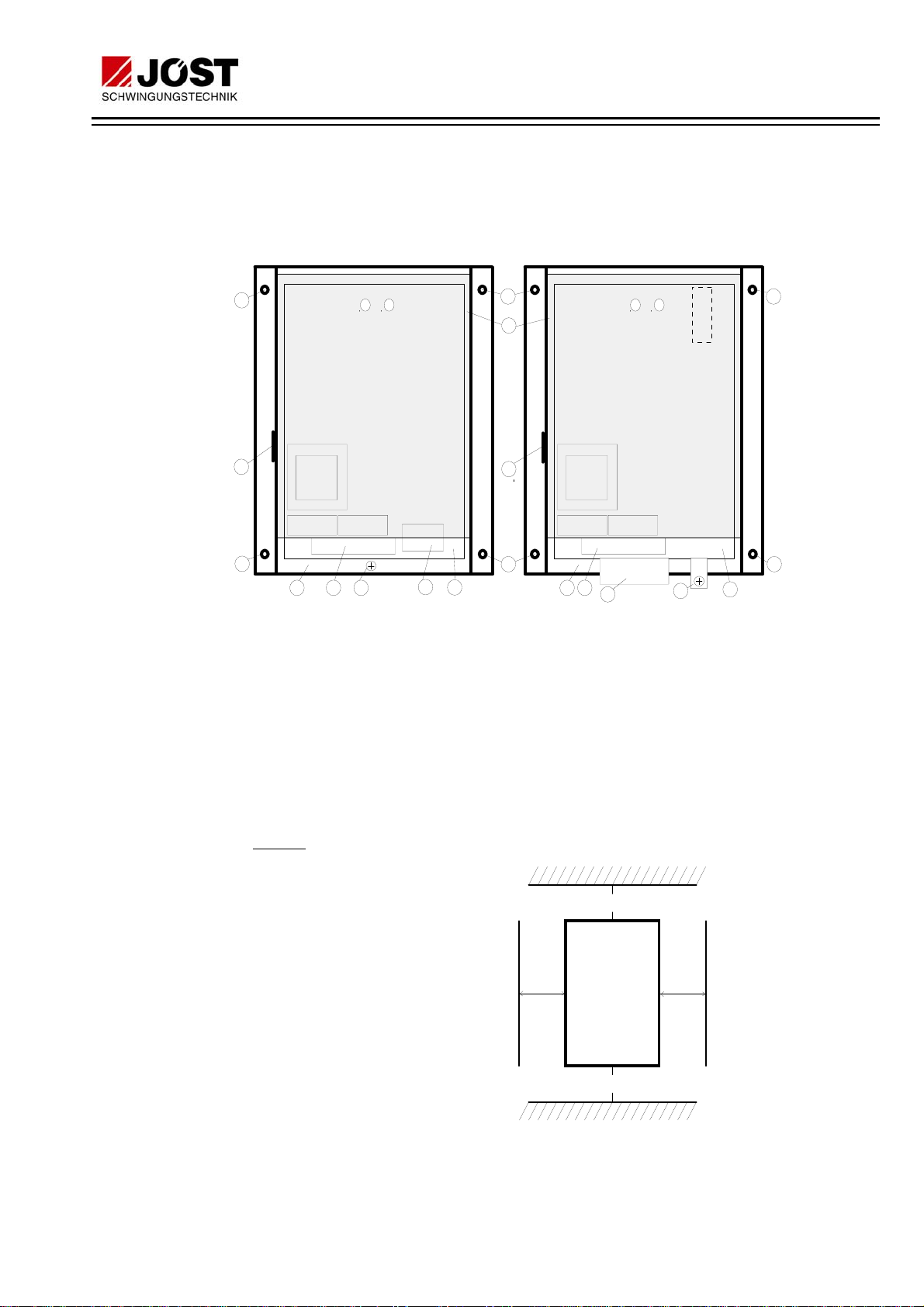
6 OPERATING PRINCIPLE
The JB brake unit operates fully electronically. A thyristor in a phase
controlled system generates an adjustable direct current in conjunction
with the electronic control logic. The control logic ensures that the direct
current does not reach the stator, through a braking contactor, until the
motor has been switched off. Said direct current creates a static
magnetic field, which counters the rotary movement of the rotor.
Automatic detection of standstill ends the braking process.
Stator windings are connected in series through the braking contactor, if
more than one motor is to be braked (see connection diagram in the
appendix).
Operating sequence:
(One motor application; on the basis of the connection diagram in the appendix):
If the brake unit is live from the mains, the LED "P" (mains) will light.
Contact 3/4 is broken and n2/n4 made. When the motor starts,
contactor K2 is locked. The brake unit receives the "motor on" signal
from the motor contactor through connection 6/7. LED "M" (motor on)
thus also lights. Contact n2/n4 (= restart lockout) breaks
simultaneously.
When the motor stops, contactor K2 drops out. The contact at 6/7
breaks. LED "M" goes out. After a short delay, contact 3/4 closes and
LED "B" (braking on) lights. Contactor K1 picks up and the braking
current flows through the motor winding, initiating braking. LED "S"
(standstill display) lights during the braking process until the motor
comes to a standstill. The braking process will be ended, unless the
braking time has been extended with trimming potentiometer "T".
Contact 3/4 breaks, contactor K1 drops out and LED "B" goes out.
Contact n2/n4 is then made again. Only now is it possible to restart the
motor.

OPERATING MANUAL for
BRAKE UNITS
JB10/... JB16/... JB26/... JB40/... JB52/...
(Installation set)
JB
7 of 19
01.96/00/Scho
7 INSTALLATION
7.1 CONSTRUCTION
The major components of JB brake units are as follows:
6
6
5
4
1
2
PE
6
6
3
784 2
6
6
5
7
3
JB10/...E000
JB16/...E000 JB26/...E000
JB40/...E000
JB52/...E000
PE
Zeit Strom Zeit Strom
8
1. Perspex cover
2. 9-pole connecting terminal X1 for control signals
3. 3-pole connecting terminal X2 for power signals
4. Heatsink with thyristor
5. Rating plate
6. Mounting holes
7. PE connection screw
8. Control board
7.2 NOTES ON INSTALLATION
Cooling:
The JB brake unit is
cooled by natural con-
vection. In order to
guarantee an adequate
air flow, the equipment
must be mounted up-
right and the minimum
distances shown in the
adjacent illustration ob-
served. The cooling air
must be as clean as
possible and free of ag-
gressive substances.
Should the cooling air
contain dust, the cooled
areas must be cleaned regularly.
JB -
Brake
100 mm
100 mm
unit
50
mm 50
mm

OPERATING MANUAL for
BRAKE UNITS
JB10/... JB16/... JB26/... JB40/... JB52/...
(Installation set)
JB
8 of 19
01.96/00/Scho
Mounting:
The JB brake unit can be
fastened to a mounting
plate by four screws.
8 NOTES ON CONNECTION AND USE
8.1 POSITION OF THE ADJ. ELEMENTS and COMPONENTS
PE
JB10/...E000
JB16/...E000 JB26/...E000
JB40/...E000
JB52/...E000
O
X1
X2
X1
X2
Bar
display
PE
8ab
34567n1n2n3n4
34567n1n2n3n4 8a b
T
P M B S sec IAmp T
P M B S sec IAmp
Mains
trans-
former
Mains
trans-
former
8.2 CONNECTIONS
8, a : Mains connection
a, b : Brake current output
3, 4 : potential free make contact for actuating the brake contactor
6, 7 : Input "motor on". Connection for the potential free auxiliary
contact of the motor contactor
n2, n4 : Potential free break contact for actuating the motor contactor
n1 : "Standstill detector" input
PE : Protective earth conductor connection
The other terminals must not be connected.
Cross-section of connectable cable:
9-pole terminal strip X1: max. 1.5 mm2
3-pole terminal strip X2: max. 4 mm2for JB10.., JB16..
max. 35 mm2for JB26.., JB40.., JB52..
Please refer to the connection diagram in the appendix for electrical
connections, or to the connection sheet packed with the unit.
O
Drilling plan: JB 10 and JB 16
Hole dia.: 4mm
144 mm
OO
O
137 mm O
Drilling plan: JB 26 and JB 52
Hole dia.: 6 mm
215 mm
OO
O
130 mm

OPERATING MANUAL for
BRAKE UNITS
JB10/... JB16/... JB26/... JB40/... JB52/...
(Installation set)
JB
9 of 19
01.96/00/Scho
8.3 ADJUSTMENT ELEMENTS
IMPORTANT NOTE:
Unauthorised resetting of the adjustment elements can
cause malfunctions in the brake unit.
Trimming potentiometers:
Two trimming potentiometers are mounted on the control board.
Operation of the trimming potentiometers:
I : Setting the brake current IBr
Extreme anti-clockwise setting: minimum brake current
Extreme clockwise setting: maximum brake current
T : Setting the subsequent braking time
Extreme anti-clockwise setting: no subsequent braking time
Extreme clockwise setting: approximately 20 seconds
subsequent braking time
8.4 MOTOR CONTROL SYSTEM AND BRAKE UNIT
The JB brake unit must be used in conjunction with an existing or newly
built motor control system. Suitable connection diagrams for machines
with one or two motors may be found in the appendix.
The brake unit requires only a two-phase mains connection and must be
fused, as stated in the appendix. The cables to terminals X2.8/a/b must
have dimensions appropriate to the brake unit fuse.
The requisite braking contactor must have the same capacity as the
motor contactor. During switching the braking contactor on and off no
current passes through the main contacts.
In the case of machines with two or more drives, each
motor must be connected to the mains through its own
motor contactor. Failure to observe this requirement will
result in short-circuiting of the brake unit.
Do not open the brake contactor during braking! Do not
operate the brake contactor by hand! Failure to observe
this requirement can destroy the brake contactor and the
brake unit.
Terminal X1.n1 is the measurement input for detecting standstill. The
cable must be protected from the auxiliary switch of the brake contactor
as shown in the connection diagram.
Local requirements for earthing and cables must be observed.
8.5 OVERHEATING PROTECTION (Only JB26/... JB40/... JB52/...)
These units have additional overheating protection. Should the heat sink
become too hot due to over-frequent braking, LED "O" will flash.
Switching on the motor will then be prevented, as contact n2/n4 will
remain broken. LED "O" will go out when sufficient cooling has taken
place. The motor can then be restarted.
9 COMMISSIONING
9.1 CHECKS BEFORE SWITCHING ON THE MAINS VOLTAGE
The JB brake unit is supplied unadjusted ex works, i.e. the trimming
potentiometers T (time) and I (current) are set to their minimum (fully
anti-clockwise). The unit must first be set to the relevant vibrating plant,
as described below.
!
!

OPERATING MANUAL for
BRAKE UNITS
JB10/... JB16/... JB26/... JB40/... JB52/...
(Installation set)
JB
10 of 19
01.96/00/Scho
Please check the following points before switching on the mains voltage:
1. The brake unit must be used in conjunction with the relevant
vibrating machine.
2. The details on the brake unit rating plate must match those on
the motor. The nominal motor current (or its aggregate, in the
case of several motors) must be ≤IN[A] (Entry under "A" on
the rating plate).
3. The mains voltage must be within the voltage range specified
on the rating plate (entry under "V" on the rating plate).
4. The mains must be connected to terminals a/8.
5. The brake unit must be earthed through the PE terminal.
6. Only potential free "make" contacts may be connected to
terminals 6/7.
7. The output cable of the brake unit must be connected to
terminals a/b. The motor(s) must be connected correctly.
8. No short circuits or short circuits to earth may be present.
9. Measures must be taken to ensure compatibility with EMC
legislation (see Section 2).
10.The braking contactor K1 and the motor contactor K2 (and K3)
must be electrically interlocked! See connection diagram in the
appendix.
9.2 INTERLOCKING TEST WITHOUT BRAKING CURRENT
•Remove the motor fuses or switch off the motor protective switch.
•Turn trimming potentiometer "T" to its maximum (clockwise).
•Turn trimming potentiometer "I" to its minimum (anti-clockwise).
The mains voltage may now be switched on. LED "P" must light.
A dangerously high voltage will now be present at the JB
brake unit.
The braking and motor contactors must never be active at
the same time!
•Operate motor contactor K2 (or K3) by hand: LED "M" must light.
•Release motor contactor K2 (or K3): LED "M" will go out. LED "B"
must light and braking contactor K1 must pick up.
•Operate contactor K2 (or K3) by hand while LED "B" is alight. Braking
contactor K1 must drop out.
!

OPERATING MANUAL for
BRAKE UNITS
JB10/... JB16/... JB26/... JB40/... JB52/...
(Installation set)
JB
11 of 19
01.96/00/Scho
•Release contactor K2 (or K3). K1 will pick up again. After the braking
time (approximately 20 seconds) has elapsed, LED "B" will go out
and braking contactor K1 will drop out.
•This ends the interlocking test.
•Switch off the mains voltage.
9.3 SETTING THE BRAKING CURRENT IBr
It must be ensured that the braking and motor contactors cannot be
active at the same time (see 9.2, Interlocking Test).
A clamp-ammeter with t.r.m.s. response capability is required to set the
braking current. Connect this meter to the line which is connected to
terminal X2.b of the braking unit.
With JB26/..., JB40/..., and JB52/... units the adjustment can be a-
chieved by means of the bar display (see below).
•The mains voltage must be switched off.
•Insert the motor fuses or switch on the motor protective switch(es).
•Set trimming potentiometer "T" to its ¼ (9 o'clock) position by turning
it anti-clockwise.
•Set trimming potentiometer "I" to its minimum (fully anti-clockwise).
•Switch on the mains power.
A dangerously high voltage will now be present at the JB
brake unit.
•Start the motor and let it warm up. LEDs "P" and "M" must light.
•Switch off the motor. LED "M" will go out. LED "B" will light. The
braking contactor will pick up. Braking has commenced.
•Increase the braking current from zero until the motor is distinctly
braked, by turning trimming potentiometer "I" slowly in a clockwise
direction. Ensure that the maximum braking current of the brake unit
is not exceeded by observing the readings on the ammeter.
(With JB26/..., JB40/..., JB52/... units:
The braking current can be read off the bar display on the control
board. 1 bar = 10% of the maximum braking current IBr).
Note: A good braking effect can usually be obtained at the ½ (12
o'clock) position of trimming potentiometer "I".
•LED "S" (standstill monitoring) will light while the braking current is
flowing and the motor is still turning. LED "S" will go out at
approximately 10% of the nominal speed. The braking process ends
as soon as LED "S" goes out and any subsequent braking time set
with trimming potentiometer "T" (up to 20 seconds) has elapsed. LED
"B" will go out and the braking contactor will drop out.
Adjustment of the braking current is now completed.
10 MAINTENANCE
The JB brake unit is largely maintenance free.
However, under very dusty conditions, regular cleaning is essential.
!

OPERATING MANUAL for
BRAKE UNITS
JB10/... JB16/... JB26/... JB40/... JB52/...
(Installation set)
JB
12 of 19
01.96/00/Scho
11 FAULT FINDING
Please make a note of the following details before reporting a defect to
our service department:
−type of the braking unit (see rating plate)
−braking unit number (see rating plate)
−defects established

OPERATING MANUAL for
BRAKE UNITS
JB10/... JB16/... JB26/... JB40/... JB52/...
(Installation set)
JB
13 of 19
01.96/00/Scho
12 APPENDIX
12.1 TECHNICAL DATA
Nominal mains voltage 230, 400, 500
from JB26/... also 690 V
Mains voltage ranges with 230V: 200 - 240 V
with 400V: 380 - 430 V
with 500V: 440 - 550 V
with 690V: 600 - 700 V
Nominal mains frequency 50/60 Hz
Allocation table:
JB type / Motor nominal current/ Braking current / Fuse
JB type max. (Aggregate)-
Motor nom.current
IN[A]
max. braking
current IBr
[A]
Braking unit
fuse F1/F2
[A, time lag] *)
JB 10/... 10 36 16
JB 16/... 16 60 25
JB 26/... 26 100 50
JB 40/... 40 160 63
JB 52/... 52 200 80
*) Choose fuse max. 1.5x IN(aggregate)-motor nom. current
Braking time adjusted automatically by stand-
still monitoring at terminal X1.n1.
Subsequent braking time of 0 -
20 sec. by trimming pot. T
Braking contactor same capacitiy as motor contac-
tor
On duty time 10 %
Indicating lights 4 x LED (JB10/..., JB16/...);
5 x LED and bar display with
JB26/..., JB40/..., JB52/...
Contact loading at terminals X1.3/4 and n2/n4:
250V AC / 5A
30V DC / 5A
OTHER DATA
Tests IEC 947-4-2, Categorie B;
EN 50081-2
EN 50082-2
Type of cooling air self-cooling
Max. installation altitude 1000 m (if over 1000m: please
consult manufacturer)
Perm. moisture stress DIN 40040 F
Degree of protection (DIN 40050) IP 20

OPERATING MANUAL for
BRAKE UNITS
JB10/... JB16/... JB26/... JB40/... JB52/...
(Installation set)
JB
14 of 19
01.96/00/Scho
Operating temperature 0°C to + 40°C
Storage and transport temp. - 10°C to + 85°C
Installation position vertical
Weight 1.3 kg (JB10.., JB16..)
7,5 kg (JB26.., JB40.., JB52..)
Dimensions 158 x 185 x 110 mm
for JB10..., JB16...
145 x 270 x 180 mm
for JB26.., JB40.., JB52..

OPERATING MANUAL for
BRAKE UNITS
JB10/... JB16/... JB26/... JB40/... JB52/...
(Installation set)
JB
15 of 19
01.96/00/Scho
12.2 TYPE KEY
The designation of the JB brake unit on the rating plate is made up as
follows:
Execution:
E000: separately mounted unit
(G000: Motor braking unit in an enclosure)
Nominal mains voltage [V]
230 / 400 / 500 / 690
perm. max. (aggregate)-motor nom. current
IN[A] : 10, 16, 26, 40, 52
Control system type
12.3 DIMENSIONS a
c
e
d
b
JB10/...
JB16/... JB26/...
JB40/...
JB52/...
110 180
158 185 137 144 4,5JB10, 16
JB26, 40, 52
abcde
145 270 130 215 6,0
Depth:
type:
All dimensions in (mm)
JB10/ 400 E000

OPERATING MANUAL for
BRAKE UNITS
JB10/... JB16/... JB26/... JB40/... JB52/...
(Installation set)
JB
16 of 19
01.96/00/Scho
12.4 LINE REACTOR - Allocation / Dimensions / Weight
Only with the brake unit Type JB16/500E000 a line reactor must be inserted into
the inlet to clamp „8”. This line reactor is delivered loose.
With the types JB26, 40, 52 the line reactor is already built in the unit.
HINWEIS: Brake unit typ JB10/... (all Mains voltage) and JB16/... (230V und 400V
mains voltage) do not need a serial line reactor.
Zuordnungstabelle: JB-Typ / Netzdrossel
Netzdrossel
JB-Type Type Dimensions
(B x H x T)
[mm]
Drilling
mass
(b x h) [mm]
Bore-
hole ∅
[mm]
Weight
[kg]
JB16/500.. KS 0,075 90x75x110 47x57 4 1,5
Dimensional drawing:
Line reactor
T
Hh
b
B

OPERATING MANUAL for
BRAKE UNITS
JB10/... JB16/... JB26/... JB40/... JB52/...
(Installation set)
JB
17 of 19
01.96/00/Scho
12.5 CONNECTION DIAGRAMM (example for 1 motor)
VIBRATOR
M
3
UVW
PE
M1
1
2
3
4
5
6
K2 JB../...E000
a8 3 n2 6
ab 4 n4n1 7
PE
G1
A1
A2
K1 A1
A2
K2
13
14
135
246
Q1 F1 F2
2A
F3
K1 K2 S1
K2 K2
K1
S2
13
14
Q1
F4 L
N
L1
L2
L3
1
2
3
4
5
6
K1
BRAKING M1
MOTOR
EXAMPLE FOR CONTROL CIRCUIT WITH PLC
PLC I/O
A1
A2
K2
K1
K2
13
14
Q1
3n26
4n47
G1
0

OPERATING MANUAL for
BRAKE UNITS
JB10/... JB16/... JB26/... JB40/... JB52/...
(Installation set)
JB
18 of 19
01.96/00/Scho
12.6 CONNECTION DIAGRAMM (example for 2 motors)
VIBRATOR
M
3
UVW
PE
M1
1
2
3
4
5
6
K2 1
2
3
4
5
6
K3
M
3
UVW
PE
M2
VIBRATOR
JB../...E000
a8 3 n2 6
ab 4 n4n1 7
PE
G1
A1
A2
K1 A1
A2
K2 A1
A2
K3
13
14
13
14
135
246
Q1
135
246
Q2 F1 F2
2A
F3
1
2
K1 3
4
5
6K1 K2
K3
S1
K2 K3 K2
K3
K1
S2
13
14
Q1
13
14
Q2
F4 L
N
L1
L2
L3
BRAKING MOTORS
M1 M2
0
EXAMPLE FOR CONTROL CIRCUIT WITH PLC
PLC I/O
13
14
Q2
A1
A2
K2 A1
A2
K3
K1
K2
K3
3n26
4n47
G1

OPERATING MANUAL for
BRAKE UNITS
JB10/... JB16/... JB26/... JB40/... JB52/...
(Installation set)
JB
19 of 19
01.96/00/Scho
12.7 CONNECTION DIAGRAMM JB10/...E000 (example 2 motors each with In <1,5A)
L
N
L1
L2
L3
BRAKING MOTORS
M1 M2
K2
K3
13
14
Q1
13
14
Q2
F4
0
K3K2
S1
K3
K2
F2F1
a8 3 n2 6
ab 4n4n1 7
PE
G1
135
246
Q2
13
14
Vibrator
M
3
UVW
PE
M2
1
2
3
4
5
6
K3
135
246
Q1
13
14
1
2
3
4
5
6
K2
M
3
UVW
PE
M1
Vibrator
1
2
3
4
5
6
K1a 1
2
3
4
5
6
K1b
2A
F3
S2
K1a
K1b
A1
A2
K2 A1
A2
K3
A1
A2
K1b
A1
A2
K1a
JB10/...E000
(In < 1,5A) (In < 1,5A)
K1a
Example for control circuit with PLC
SPS I/O
13
14
Q2
A1
A2
K2 A1
A2
K3
K1
K2
K3
3n26
4n47
G1
L1*)
*) L1: See Chapter 12.4
Direction of rotation:
Please note the operating manual!
This manual suits for next models
4
Table of contents
Popular Industrial Electrical manuals by other brands

Murata
Murata GRM188C81C475KE11 Series Reference sheet

Prodigit
Prodigit 3302F Mainframe Operation manual

Murata
Murata GRM0335C1H120JA01 Series Reference sheet

Murata
Murata GRM155R71C224KA12 Series Reference sheet

Murata
Murata GRM155R71H333KE14 Series Reference sheet

Murata
Murata GRM155R61A105KE15 Series Reference sheet

Elvaco
Elvaco CMeX20w quick start guide

MICRO-EPSILON
MICRO-EPSILON boreCONTROL instruction manual

Murata
Murata GRM022R60J272KE19 Series Reference sheet

Guildline
Guildline 9230A Series Technical manual

Murata
Murata GRM1885C1H6R2BA01 Series Reference sheet

Murata
Murata GRM319R72A102KA01 Series Reference sheet