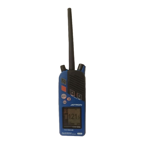
jotron Tron TR30 AIR User manual

www.jotron.com

Tron TR30 AIR
2

Tron TR30 AIR
3
Table of Contents
1GENERAL 5
2IMPORTANT INFORMATION 6
3PRODUCT DESCRIPTION 7
4PRODUCT IMAGES 8
5FUNCTIONAL DESCRIPTION9
5.1 Tron TR30 AIR components 9
5.2 Antenna 10
5.3 Emergency battery 10
5.4 Test battery 11
5.5 Battery endurance 11
5.6 RH-30 Holder 11
6INSTALLATION 13
7EMERGENCY USE 14
8OPERATION INSTRUCTIONS16
8.1 Turning on the radio 16
8.2 Channel selection 16
8.3 Channel 121.5MHz button 16
8.4 Volume adjustment 17
8.5 Squelch adjustment 17
8.6 Key lock and unlock 17
8.7 Menus 18
9MAINTENANCE 21
9.1 Regular inspection 21
9.2 Regular testing 22
10 TEST AND MAINTENANCE RECORDS 23
11 BATTERY SAFETY INSTRUCTION 24
11.1 Hazard identification 24
For complete Product Safety Data Sheet for battery cells, see 24
11.2 First aid measures 24
11.3 Fire fighting measures 25
11.4 Handling and storage 25
11.5 Transportation 25

Tron TR30 AIR
4
12 ACCESSORIES AND SPARE PARTS 26
12.1 Optional accessories 26
12.2 Spare parts 26
12.3 Counterfeit spare parts 26
13 RECYCLING AND DISPOSAL27
14 WARRANTY 28
14.1 Service agents 29
15 STANDARDS 30
16 ABBREVIATIONS 32
17 TECHNICAL SPECIFICATIONS 33
17.1 Product specification 33
18 AMENDMENT RECORDS 34
19 EMERGENCY INSTRUCTIONS35

Tron TR30 AIR
5
1GENERAL
Jotron manufactures safety equipment designed for the search and rescue of human life
and property. For safety equipment to be effective according to the design parameters it
is important that all products are handled, maintained, serviced and stowed in
compliance with this manual.
Copies of all Jotron documentation can be downloaded from our website:
www.jotron.com.
All information contained within this manual has been verified and is to our knowledge
correct, however, Jotron reserves the right to make changes to any product(s) or
module(s) described herein to improve reliability, function or design, without further
notice.
The following three symbols are in use throughout this manual:
This symbol is used to highlight information.
This symbol is used to draw attention to important details.
This symbol is used to highlight information that if not followed can result
in personal injury or body harm.
Jotron is not liable for consequential or special damages and cannot be held responsible
for any damages or injury arising either directly or indirectly due to an error or omission
of information, misuse of a product, breach of procedures, or for failure of any specific
component or other part of the equipment.
Tron TR30 AIR
6
2IMPORTANT INFORMATION
Below are instructions for keeping the radio log and the radio operator's obligation
according to national and international regulation:
1. The radio log shall be kept in accordance with requirements in the Radio
Regulation, SOLAS Convention, national regulations regarding radio installations
and the STCW Convention (STCW 95 including the STCW Code) including relevant
regulation regarding watch keeping on board passenger and cargo ships.
2. Unauthorized transmissions and incidents harmful interference should, if
possible, be identified, recorded in the radio log and brought to the attention of
the Administration in compliance with the Radio Regulations, together with an
appropriate extract from the radio log (STCW Code BVIII/2 No. 32).

Tron TR30 AIR
7
3PRODUCT DESCRIPTION
The Tron TR30 AIR is a ruggedly designed radio made for easy operation. It is a portable
emergency VHF radio for two-way communication between vessel and aircraft. The
radio is possible to operate using one hand, even when wearing gloves. The high
contrast graphical display including integrated back lighting of the display and keys are
very effective for visibility and usage in low light conditions.
It is also resistant to oil, seawater and sunlight. This radio is compact in size with smooth
edges to avoid damage to clothing or a raft.
The Tron TR30 AIR radio is waterproof down to 1 meter and floats in freshwater, battery
included. The radio is designed with a self-draining loudspeaker. The Tron TR30 AIR is
only waterproof when the antenna and jack cover are assembled on the radio correctly.
The Tron TR30 AIR package includes the following components:
•Tron TR30 AIR radio
•TR30 Emergency battery (orange)
•TR30 Test battery (black)
•RH-30 Holder
•Antenna
•Belt clip
•Wrist strap
•User Manual
Part number: 101700 Tron TR30 AIR

Tron TR30 AIR
8
4PRODUCT IMAGES
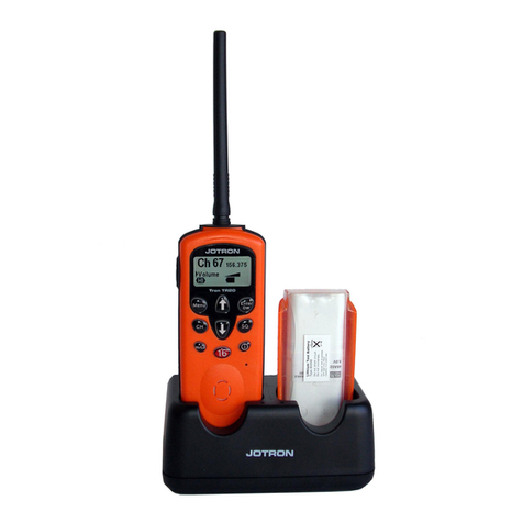
Figure 2: Tron TR30 AIR in RH-30 Holder
Figure 1: Tron TR30 AIR

Tron TR30 AIR
9
5FUNCTIONAL DESCRIPTION
5.1 Tron TR30 AIR components
An overview of the radio components:
Figure 3: Tron TR30 AIR components
1. Antenna TR30 AIR
2. Volume, squelch and
monitor control
3. Loudspeaker
4. Up button
5. Down button
6. Backlight button
7. Emergency mode indicator
8. Frequency indicator
9. Microphone
10. Squelch and signal
strength indicator
11. Transmitter power
indicator (only visible
when transmitting)
12. Battery status indicator
13. Volume control indicator
14. Key lock/unlock button
15. Enter button
16. 121.5 button (instant
access)
17. PTT transmit button
18. On/off button
19. Jack cover (external
accessories connector)

Tron TR30 AIR
10
5.2 Antenna
The antenna for the Tron TR30 AIR is fitted with a standard SMA connector. The antenna
shall be marked with “JOTRON TR30 AIR”. Make sure to use only original and approved
Jotron antenna.
Be sure to use correct antenna type. Antenna for Tron TR30 AIR, shall be marked with
JOTRON TR30 AIR on the sides.
The Tron TR30 AIR unit is not waterproof when the standard antenna is not attached or
if the antenna is not assembled correctly.
5.3 Emergency battery
The Emergency battery (orange) is a Lithium metal battery.
This battery is specially designed for use in distress situation
and cannot be recharged. Keep the Emergency battery in the
RH-30 Holder, then it is easily accessible in a distress
situation.
Always bring a sealed Emergency battery with the radio when
boarding a lifeboat or raft.
See chapter 11 for Battery Safety Instruction.
The emergency battery is a single use item. You must replace the battery
before the battery expiry date and/or if the protective seal on the battery is broken.
New Emergency batteries can be ordered from your local Jotron dealer or from
sales@jotron.com (Order No: 101035 Spare TR30 Emergency Battery).
Figure 4: Emergency battery

Tron TR30 AIR
11
5.4 Test battery
Test battery shall be used for test and training.
Ensure you check the batteries for damage prior to use.
See chapter 11 for Battery Safety Instruction.
New Test battery can be ordered from your local Jotron
dealer or from sales@jotron.com (Order No: 101710 Spare
TR30 Test Battery).
5.5 Battery endurance
The standby and operation times of the batteries is listed below:
Battery
Standby hours at -20°C
Multi-usage at -20°C 1
TR30 Emergency battery 60 hours >20 hours
TR30 Test battery 60 hours >20 hours
5.6 RH-30 Holder
The RH-30 Holder is without any electronics or any charging possibility. The holder has
possibilities to store one radio with or without a mounted Test battery, and an
Emergency battery.
Jotron recommend that the Test battery is always mounted on the radio when not in use
and stored in the RH-30 Holder. This will not drain the battery when the radio is turned
OFF
The RH-30 Holder can both be mounted on a horizontal or a vertical surface.
1Emergency battery lifetime hours have been tested in accordance with 10:10:80 ratio
(Send:Listen:Standby).
Figure 5: TR30 Test battery

Tron TR30 AIR
12
An overview of the RH-30 Holder components:
Figure 6: RH-30 Holder components
1. Battery storage bay
2. Radio storage bay
3. Holes for vertical mounting (36mm
spacing)
4. Holes for horizontal mounting (43mm
spacing)
Figure 7: Tron TR30 AIR radio
and
Emergency battery in
Holder

Tron TR30 AIR
13
6INSTALLATION
Upon receipt of the radio, do the following:
1. Mount the RH-30 Holder. It can be mounted either on a horizontal or vertical
surface, using the respectively holes, see chapter 5.6. The RH-30 Holder should be
mounded in a place where it can always be easily accessible.
2. Connect the antenna to the radio. When assembling the antenna to the radio,
ensure you hold it at the base while turning it clockwise. When the antenna starts to
resist turning, turn it another ¼ turn.
3. Mount the Test battery on the radio.
4. Place emergency battery in the battery storage bay in the RH-30 Holder and the
radio in the radio bay.
The emergency battery should only be installed on the radio in a Distress
situation.
Figure 8: Tron TR30 Air in Holder

Tron TR30 AIR
14
7EMERGENCY USE
To install the emergency battery on the Tron TR30 AIR, do the following:
1. Pull back and remove the
emergency seal sticker on the
battery.
Rip the sticker off at the perforated edge.
2. Using the fixing track, mount the
Emergency battery onto the
back of the radio.
Ensure you enter the bottom
edge of the battery into the
bottom edge of the radio. Do
not force the battery

Tron TR30 AIR
15
3. Squeeze in the black finger grips
on either side of the battery to
lock the battery into place
4. Turn on radio
5. Push PTT to transmit.

Tron TR30 AIR
16
8OPERATION INSTRUCTIONS
The TR30 AIR shall only be used with Emergency battery or Test battery. The Emergency
battery is for use in a distress situation. In case of a test or training, use a Test battery.
If the jack cover is removed, for example when using an accessory, the radio is no longer
waterproof.
The antenna, battery and jack cover must be correctly assembled on the radio in order
to be waterproof.
8.1 Turning on the radio
Press and hold the
On/off button for approximately 3
seconds to turn the radio on.
The radio
loads the following settings:
Frequency 121.5MHz
High volume
Low squelch
8.2 Channel selection
Press the
Up-or Down arrow buttons to change the frequency.
8.3 Channel 121.5MHz button
Press the
121.5 button to jump directly to 121.5MHz
emergency
frequency.

Tron TR30 AIR
17
8.4 Volume adjustment
Turn the
volume control clockwise to increase and anti-
clockwise to reduce
the volume.
The volume symbol in the display indicates the volume level.
Ensure that you do not
press down the volume control while
adjusting the volume.
8.5 Squelch adjustment
Press and turn the
squelch control anti-
clockwise to increase receiver sensitivity.
The squelch bar appears on the screen display
indicating the current active
sensitivity level.
When adjusted fully to the left, the squelch is
completely open. Adjusting to the right lowers
the receiver sensitivity.
The signal strength of the current channel appears on the bar below the squelch bar. If
the received signal is strong enough, the squelch opens and voice is received. This is
indicated by the Rx symbol.
When the squelch control is pressed twice, it opens t
he squelch immediately. Press
twice again to recall the previous squelch setting.
When the receiver signal is too distorted (by
radio noise) to be readable, the loudspeaker or
speaker mic is automatically muted. This is
indicated by the Noise Cancel (NC)
symbol that
appears in the display
8.6 Key lock and unlock
Press and hold the
Key lock/unlock button for 2
seconds to lock or unlock the buttons on the front
A key symbol appears when the radio is locked
PTT, Instant access 121.5MHz, volume and
squelch
are still available when the radio is locked.

Tron TR30 AIR
18
8.7 Menus
Press the Up-and Down arrow buttons at the same time to enter or
exit the menu system. Use the up/down arrow buttons to navigate
and select using Enter button.
Exit
:
Display screen: Menu
number:
Use this menu option to exit the menu system.
Settings:
Menu
number:
Use this
menu option to adjust the following
settings:
Key sound
Key volume
Backlight level
Contrast
1

Tron TR30 AIR
19
Key sound:
Menu
number:
Use this menu option to choose an audio
tone.
You can choose between four different tones.
Using the up/down arrow keys,
select from 1-4.
1.1
Key volume:
Menu
number:
Use this menu option to set the volume of the key
sound.
(Off=0, low to high=1
-6)
1.2
Backlight level:
Menu
number:
Use this menu option to set the display backlight
level.
(Off=0, low=1 or
high=2)
1.3
Contrast:
Menu
number:
Use this menu option to set the display
contrast level
(Low=1, medium= 2 or high=3)
1.4

Tron TR30 AIR
20
System:
Menu
number:
Use this menu option to access the following
information:
Serial Number
SW version
HW version
2
Serial Number:
Menu
number:
Use this menu option to find the
serial number of
the radio
2.1
SW Version:
Menu
number:
Use this menu option to find the
software version
of this radio.
2.2
HW Version:
Menu
number:
Use this menu option to find the
hardware version
of this radio.
2.3
Other manuals for Tron TR30 AIR
1
Table of contents
Other jotron Radio manuals

jotron
jotron Tron TR30 User manual

jotron
jotron Tron TR20 PLUS User manual

jotron
jotron Tron TR30 AIR User manual

jotron
jotron Tron TR30 User manual

jotron
jotron TR-7750C User manual

jotron
jotron TR-810 User manual

jotron
jotron Tron TR30 User manual

jotron
jotron TR-910 User manual

jotron
jotron Tron TR20 GMDSS User manual