JPW JET MBS-708CSB User manual

2
CE-Conformity Declaration
CE-Konformitätserklärung
Déclaration de Conformité CE
Product / Produkt / Produit:
Metal Band Saw / Metallbandsäge / Scie à ruban
MBS-708CSB
Brand / Marke / Marque:
JET
Manufacturer / Hersteller / Fabricant:
JPW (Tool) AG, Tämperlistrasse 5, CH-8117 Fällanden
Schweiz / Suisse / Switzerland
We hereby declare that this product complies with the regulations
Wir erklären hiermit, dass dieses Produkt der folgenden Richtlinie entspricht
Par la présente, nous déclarons que ce produit correspond aux directives suivantes
2006/42/EC
Machinery Directive / Maschinenrichtlinie / Directive Machines
2014/30/EU
electromagnetic compatibility
elektromagnetische Verträglichkeit
compatibilité électromagnétique
designed in consideration of the standards
und entsprechend folgender zusätzlicher Normen entwickelt wurde
et été développé dans le respect des normes complémentaires suivantes
EN ISO 12100:2010
EN 13898:2003+A1:2009
EN 60204-1:2006/AC2010
EN 61000-6-2:2005
EN 61000-6-4:2007/A1:2011
Responsible for the Documentation / Dokumentations-Verantwortung / Résponsabilité de Documentation:
Hansjörg Meier
Head Product-Mgmt. / Leiter Produkt-Mgmt. / Resp. Gestion des Produits
JPW (Tool) AG
2017-10-13 Jan Dätwyler, General Manager
JPW (Tool) AG, Tämperlistrasse 5, CH-8117 Fällanden
Schweiz / Suisse / Switzerland

3
Table of Contents
TABLE OF CONTENTS................................................................................................................... 3
UNPACKING..........................................................................................................................................................................7
CLEANING ............................................................................................................................................................................7
PRIOR TO OPERATION .............................................................................................................................................................7
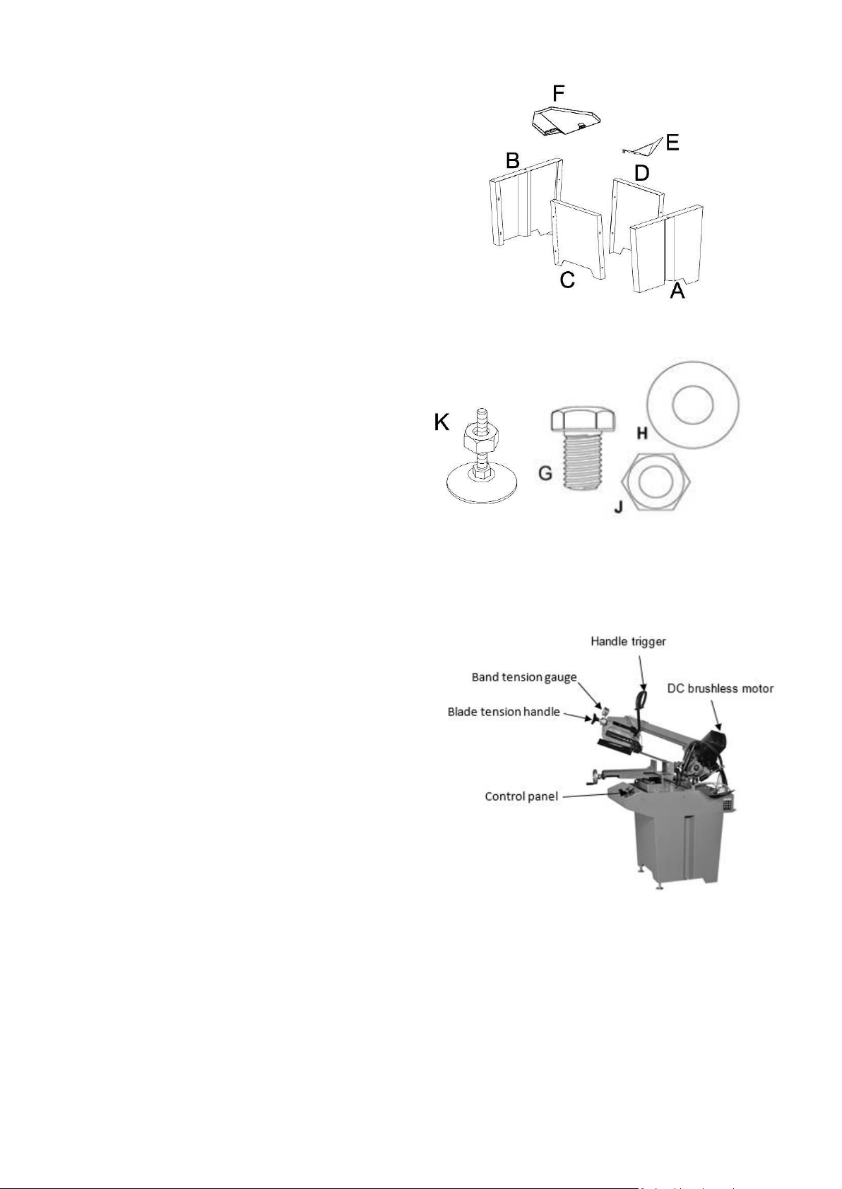
SET-UP AND ASSEMBLY ............................................................................................................... 8
STAND.................................................................................................................................................................................8
HARDWARE ..........................................................................................................................................................................8
SAW HEAD ...........................................................................................................................................................................8
WORK STOP .........................................................................................................................................................................9
STAND ASSEMBLY ..................................................................................................................................................................9
MOUNTING SAW TO STAND.....................................................................................................................................................9
INSTALL THE EXTENSION TRAYS ...............................................................................................................................................10
MACHINE BASE ...................................................................................................................................................................10
COOLANT SYSTEM................................................................................................................................................................10
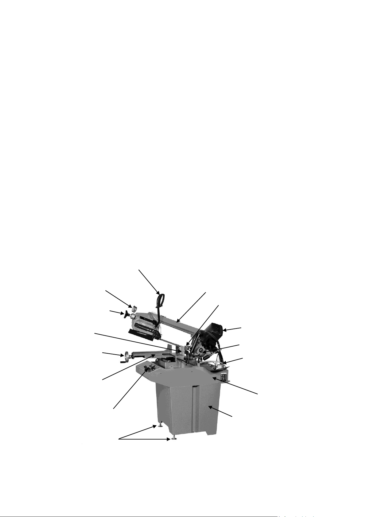
OPERATING CONTROLS ............................................................................................................. 11
OPERATION OF CONTROL PANEL.............................................................................................................................................11
OPERATION .............................................................................................................................. 12
SPRING SETTING ..................................................................................................................................................................12
COUNTERBALANCE SPRING.....................................................................................................................................................12
GENERAL OPERATING PROCEDURE ...........................................................................................................................................12
ADJUSTMENTS .......................................................................................................................... 13
ADJUSTING MOVABLE BLADE GUIDE ........................................................................................................................................13
VISE OPERATION .................................................................................................................................................................13
ADJUSTING BLADE TENSION...................................................................................................................................................13
BLADE INSTALLATION/REPLACEMENT .......................................................................................................................................14
TEST CUTTING TO VERIFY ADJUSTMENT.....................................................................................................................................14
ADJUSTING BLADE SQUARE TO TABLE ......................................................................................................................................15
ADJUSTING BLADE SQUARE TO VISE ........................................................................................................................................15
SQUARING BLADE TO VISE......................................................................................................................................................15
ADJUSTING BLADE TRACKING .................................................................................................................................................16
ADJUSTING BOW ANGLE FOR MITER CUTS.................................................................................................................................16
ADJUSTING BLADE GUIDE BEARINGS........................................................................................................................................17
SELECTING THE BLADE ..........................................................................................................................................................17
BLADE SPEEDS........................................................................................................................... 18
EVALUATING CUTTING EFFICIENCY ............................................................................................ 18
MAINTENANCE ......................................................................................................................... 19
LUBRICATION............................................................................................................................ 19
TROUBLESHOOTING.................................................................................................................. 20
REPLACEMENT PARTS ............................................................................................................... 22
SAW TABLE ASSEMBLY DRAWING (1 OF 3) -EXPLODED VIEW ......................................................................................................22
SAW BOW ASSEMBLY DRAWING (2 OF 3) -EXPLODED VIEW........................................................................................................23
SAW STAND ASSEMBLY DRAWING (3 OF 3) -EXPLODED VIEW .....................................................................................................24
MBS-708CSB PART LIST .....................................................................................................................................................25
WIRING DIAGRAMS................................................................................................................... 30
MBS-708CSB ELECTRICAL APPLIANCE DESCRIPTION .................................................................................................................31

4
1. Read and understand the entire owner's manual before attempting assembly or operation.
2. Read and understand the warnings posted on the machine and in this manual. Failure to comply with all of these
warnings may cause serious injury.
3. Replace the warning labels if they become obscured or removed.
4. This band saw is designed and intended for use by properly trained and experienced personnel only. If you are not
familiar with the proper and safe operation of a band saw, do not use until proper training and knowledge have
been obtained.
5. Do not use this band saw for other than its intended use. If used for other purposes, JPW (TOOLS) Inc., disclaims
any real or implied warranty and holds itself harmless from any injury that may result from that use.
6. Always wear approved safety glasses/face shields while using this band saw. Everyday eyeglasses only have impact
resistant lenses; they are not safety glasses.
7. Before operating this band saw, remove tie, rings, watches and other jewelry, and roll sleeves up past the elbows.
Remove all loose clothing and confine long hair. Non-slip footwear or anti-skid floor strips are recommended. Do
not wear gloves.
8. Wear ear protectors (plugs or muffs) during extended periods of operation.
9. Some dust created by power sanding, sawing, grinding, drilling and other construction activities contain chemicals
known to cause cancer, birth defects or other reproductive harm. Some examples of these chemicals are:
Lead from lead based paint.
Crystalline silica from bricks, cement and other masonry products.
Arsenic and chromium from chemically treated lumber.
Your risk of exposure varies, depending on how often you do this type of work. To reduce your exposure to these
chemicals, work in a well-ventilated area and work with approved safety equipment, such as face or dust masks
that are specifically designed to filter out microscopic particles.
10. Do not operate this machine while tired or under the influence of drugs, alcohol or any medication.
11. Make certain the switch is in the OFF position before connecting the machine to the power supply.
12. Make certain the machine is properly grounded.
13. Make all machine adjustments or maintenance with the machine unplugged from the power source.
14. Remove adjusting keys and wrenches. Form a habit of checking to see that keys and adjusting wrenches are
removed from the machine before turning it on.
15. Keep safety guards in place at all times when the machine is in use. If removed for maintenance purposes, use
extreme caution and replace the guards immediately.
16. Check damaged parts. Before further use of the machine, a guard or other part that is damaged should be carefully
checked to determine that it will operate properly and perform its intended function. Check for alignment of
moving parts, binding of moving parts, breakage of parts, mounting and any other conditions that may affect its
operation. A guard or other part that is damaged should be properly repaired or replaced.
17. Provide for adequate space surrounding work area and non-glare, overhead lighting.
18. Keep the floor around the machine clean and free of scrap material, oil and grease.
19. Keep visitors a safe distance from the work area. Keep children away.
20. Make your workshop child proof with padlocks, master switches or by removing starter keys.
21. Give your work undivided attention. Looking around, carrying on a conversation and “horse-play” are careless acts
that can result in serious injury.

5
22. Maintain a balanced stance at all times so that you do not fall or lean against the blade or other moving parts. Do
not overreach or use excessive force to perform any machine operation.
23. Use the right tool at the correct speed and feed rate. Do not force a tool or attachment to do a job for which it was
not designed. The right tool will do the job better and safer.
24. Use recommended accessories; improper accessories may be hazardous.
25. Maintain tools with care. Keep blades sharp and clean for the best and safest performance. Follow instructions for
lubricating and changing accessories.
26. Make sure the work piece is securely clamped in the vise. Never use your hand to hold the work piece.
27. Turn off the machine before cleaning. Use a brush or compressed air to remove chips or debris —do not use your
hands.
28. Do not stand on the machine. Serious injury could occur if the machine tips over.
29. Never leave the machine running unattended. Turn the power off and do not leave the machine until the blade
comes to a complete stop.
30. Remove loose items and unnecessary work pieces from the area before starting the machine.
31. Pull the mains plug if the machine is not in use.
Familiarize yourself with the following safety notices used in this manual:
This means that if precautions are not heeded, it may result in minor injury and/or possible machine
damage.
This means that if precautions are not heeded, it may result in serious injury or possibly even death.

6
SPECIFICATIONS
Model ..........................................................................................................................................................MBS-708CSB
Stock Number...............................................................................................................................................50000316M
Round at 90°(mm) ............................................................................................................................................... 180
Round at Right 45°(mm) ...................................................................................................................................... 125
Round at Left 45°(mm) ....................................................................................................................................... 140
Round at 60°(mm) ................................................................................................................................................. 95
Rectangle at 90°(mm) .................................................................................................................................165 x 220
Rectangle at Right 45°(mm) ..........................................................................................................................150 x 70
Rectangle at Left 45°(mm) .........................................................................................................................135 x 150
Rectangle at 60°(mm) .....................................................................................................................................90 x 95
Blade Size (mm)....................................................................................................................................... 19 x 0.9 x 2285
Blade Tension (kg/cm2)............................................................................................................................. 1500~1700
Blade material...................................................................................................................................... HSS M42 5/8T
Blade Speeds (MPM) ........................................................................................................................................... 35 ~ 85
Blade Wheel Diameter (mm) .................................................................................................................................... 250
Coolant Capacity (Liter)............................................................................................................................................... 10
Bed Height (mm) ....................................................................................................................................................... 920
Motor (DC Brushless) ........................................................................................................................0.75kW, 230V, 1Ph
Floor Space Required (L x W x H) (mm).............................................................................................. 1140 x 562 x 1295
Machine Package (mm)........................................................................................................................ 1250 x 580 x 912
Net Weight (kg) ......................................................................................................................................................... 120
Gross Weight (kg)...................................................................................................................................................... 145
Coolant pump
Handle trigger
Blade tension handle
Fixed vise
Band tension gauge
Adjustable level
pad
Steel stand
Control panel
Water tray with coolant tank
Adjustable vise
Rotating arm for miter
cuts
DC brushless motor
Vise locking Wheel
Blade guide
Bow

7
SHIPPING CONTENT
Read and understand the entire contents of this
manual before attempting assembly or
operation! Failure to comply may cause serious
injury.
Unpacking
Remove box and wood crating completely from
around saw. Check for shipping damage. Report
any damage immediately to your distributor and
shipping agent. Do not discard any shipping
material until the Table Saw is assembled and
running properly.
Compare the contents of your container with the
parts lists in the next page to make sure all parts
are intact. Missing parts, if any, should be reported
to your distributor. Read the instruction manual
thoroughly for assembly, maintenance and safety
instructions.
1. Unbolt the saw from the skid.
2. Carefully slide the saw from the pallet onto
the floor.
Do not connect the saw to the power source
until all assembly has been completed! Failure to
comply may cause serious injury!
The Metal Saw should be placed in an area with a
sturdy level floor, good ventilation and sufficient
lighting. Leave enough space around the machine
for mounting extension trays and bow swivel, and
loading and off-loading stock and general
maintenance work.
Cleaning
Exposed metal surfaces, such as the table top and
moveable vise sliding area, have been given a
protective coating at the factory. This should be
removed with a soft cloth moistened with
kerosene. Do not use acetone, gasoline, or lacquer
thinner for this purpose. Do not use solvents on
plastic parts, and do not use an abrasive pad
because it may scratch the surfaces.
Prior to operation
1. Check to see blade tooth direction matches
diagram on saw body.
2. Check to see that blade is properly seated on
wheels after proper tension has been applied.
3. Set blade guide roller bearing snug against
blade. See Adjusting Blade Guide Bearings for
more details.
4. Check for slight clearance between vertical
rollers and back of blade.
5. Position movable blade guide as close to work
as possible.
6. Select proper speed and feed rate for
materials being cut.
7. Material to be cut must be held securely in
vise.
8. Do not start cut on a sharp edge. File the
edge first.

8
Set-Up and Assembly
Stand
Referring to Figure 1.
1 Band Saw (not shown)
1 Front Stand Panel (A)
1 Rear Stand Panel (B)
1 Left Stand Panel (C)
1 Right Stand Panel (D)
1 Extension Water Tray for Front (E)
1 Extension Water Tray for Rear (F)
1 Operating Instructions manual (not shown)
Hardware
Referring to Figure 2.
8 M8 x 15 Hex Head Cap Screw (G)
8 5/16” Flat Washer (H)
8 M8 Hex Nut (J)
2 Adjustment Pad w/ Hex nut (K)
Machine Features
Referring to Figure 3.
It depicts the main features of the Model MBS-708CSB
Bandsaw. The machine consists of a machine base onto
which is installed a saw head.
Saw Head
The saw head consists of a drive motor, gearbox, blade
wheels, blade guides and supports, control panel, blade
tension mechanism, wire brush, and the saw blade.
The drive wheel is installed on the output shaft of the
gearbox. The driven wheel is located on the left side of
the machine and is mounted on a shaft that is part of
the blade tension mechanism. The blade tension
mechanism is used to tighten the saw blade on the
blade wheels.
Blade tension generally requires adjustment only after
the saw blade is changed, but the tension should be
monitored with the convenient blade tension indicator.
Contents of the Carton (Fig 1)
Hardware (Fig 2)
Fig 3

9
Work Stop
Referring to Figure 4.
A work-stop is provided with the machine to allow
cutting multiple pieces of identical length. The stop
consists of a set rod onto which is installed a distance
set bracket, stop rod assembly and two lock handles.
The rod is installed in a bore in the front of the saw bed.
The distance set bracket is moved in or out on the set
rod to establish the length of the work-piece and the
stop rod can be adjusted to accommodate work-pieces
of various widths.
Stand Assembly
Referring to Figure 5.
Tools required for assembly:
Two 13mm wrenches (Note: A ratchet wrench may
speed assembly time.)
1. Assemble the rear (D1) and right side (E1)panels
with two M8 x 15 hex cap screws (A), two 5/16” flat
washers (B) and two M8 hex nuts (C). Tighten the
hex nuts.
2. Assemble E2and D2in the same manner.
3. Assemble the level pad (G) and hex nut (F) in stand.
4. Finish assembling E2to D1and E1to D2in the same
manner as above.
Mounting Saw to Stand
Remove any plastic or holding straps from around the
band saw. Areas of the machine have been given a
protective coating at the factory. This should be
removed using a soft cloth moistened with kerosene or
a cleaner-degreaser. Do not use gasoline, paint thinner,
or lacquer thinner as these will damage painted
surfaces. Do not use an abrasive pad.
Determine the final location for the saw and allow for a
sufficient work space around it.
The saw is extremely heavy. Use a
hoist to lift.
When moving the saw/stand top
assembly the cutting head, or “bow”, should be in the
down position.
Fig. 4
Assembly (Fig 5)

10
Referring to Figure 6:
1. The saw (A) and stand top (B) come as an
assembled unit. Use a hoist to lift and place the saw
onto the stand (C).
Note that the front of the saw faces the same
direction as the indented panel of the stand.
2. Adjust the stand top (B) and stand (C) so the corner
mounting holes (D) are aligned.
3. Secure the stand top (B) to the stand (C) with four
each M8 hex cap screws (E) with M8 flat washers
(F). Tighten with a 13mm hex wrench.
Install the extension trays
Refer to Fig 7.
Install the coolant collectors (R) at the left and right side
of the base.
Machine Base
Referring to Fig 8.
The base is a structure supporting the saw frame, the
vise, the bar stop, the work-piece supporter, coolant
pump, swing arm, and the coolant return plates. The
base house includes the cooling liquid tank.
Assembly (Fig 6)
Fig. 7
Fig. 8
Coolant System
Referring to Fig 9.
Oils for Lubricating Coolant
Considering the vast range of products on the market,
the user can choose the one most suited to their own
requirements, using as reference the type SHELL LUTEM
OIL ECO. THE MINIMUM PERCENTAGE OF OIL DILUTED
IN WATER IS 10 - 20 %.
Cleaning the Tan
Use hex wrench to open the plug located on the rear
base below the pump. Allow the coolant to drain-out.
Remove the filter net (P) by loosening the four screws.
Remove the pump (Q) by loosening the four screws.
Use a vacuum cleaner to vacuum chips and debris from
the tank.
Replace the plug.
Thoroughly clean the pump (Q) and replace.
Fill the tank with coolant to approximately 25mm below
the filter net (P).
Clean and replace the filter net.
R
C

11
Operating controls
Operation of Control Panel
Referring to Fig 10.
1. Emergency stop switch
Press down the Emergency switch to stop all of
machine function if any unsafely situation occurred.
2. Stop power button
O: Press to disconnect the power of motor.
3. Power on button
I: Press to connect the power of motor
4. Blade speed adjusting knob
Variable blade speed is controlled by the knob.
Turn knob clockwise to increase speed from 35
to 85 MPM. Turn knob counter clockwise to
decrease blade speed.
5. Cutting mode selection Switch
There is two cutting modes and neutral position can
be selected. Select any cutting mode the power
should be cut by the neutral position.
Manual mode.
Hydraulic flow controlled descend mode.
Turn switch left for hydraulic controlled descend
mode and right for manual mode.
6. Coolant ON/OFF Switch
I: Turn on the coolant
O: Turn off the coolant
7. Saw Arm Descend Valve
Control saw bow descent speed
Fig. 9
P
Q
Fig. 10
7
1
2
3
5
4
6

12
Fig. 12
Operation
Spring Setting
Referring to Fig 11.
Counterbalance spring
The counterbalance spring helps control the amount of
weight the saw bow puts on the work-piece when the
hydraulic control valve is fully open. The hydraulic
cylinder will not compensate for improper
counterbalance.
If the spring is not set properly, one can expect poor
performance, crooked cuts, tooth stripping, stalling,
and/or the blade running off the wheels.
Spring tension has been set by the manufacturer, and
should not require adjustment. If future problems arise,
indicating improper counterbalance, adjust spring as
follows:
1. Disconnect machine from power source.
2. Turn ON hydraulic cylinder valve and place saw bow
in horizontal position.
3. Turn feed rate valve on hydraulic cylinder
counterclockwise until it stops.
4. Place a weigh scale (such as a spring or hanging
scale) beneath blade tension handle, and lift saw
bow. Scale should indicate approximately 5 to 6 kg
(11-13 LB).
5. If adjustment is needed, loosen wing nut A on the
eye bolt, until scale indicates 5 to 6 kg (11-13 LB).
Fig. 11
General operating procedure
Referring to Fig 12.
1. Raise bow until it will clear work-piece by a few
inches, and close hydraulic cylinder valve to secure
it in place.
NOTE: Never start a cut with blade contacting
work-piece.
2. Place work-piece in vise and tighten vise. The work-
piece should be fitted directly between the jaws
without adding other objects.
When work-piece to be cut is a profiled section, flat
piece or special shape, refer to examples in Figure
29 for proper clamping positions. The top row
shows acceptable clamping positions; the bottom
row shows unacceptable positions.
If thickness of profiled section is very thin, a piece
which duplicates the profile should be fitted inside
the work-piece itself, to prevent work-piece being
crushed between the jaws.
A

13
Adjustments
Adjusting movable Blade Guide
Refer to Fig 13.
Red blade guard must be reinstalled
after new blade is fitted.
1. Disconnect machine from the power source.
2. Loosen lock handle A and knob B. Slide blade guide
assemblies as close as possible to the material for
cutting stably.
3. Tighten handle A and knob B after adjusting.
Fig.13
Vise Operation
Refer to Fig 14.
Do not make any adjustments or
load/unload material from vise while machine is
running! Failure to comply may cause serious injury!
The vise is mounted on the machine base. Follow the
easy steps to open or close the vise.
1. Turn the hand wheel (A) Fig.14 counter clockwise
to open the vise jaw to allow the width of vise can
load work piece.
2. Make sure the work piece is well located on the
table. Turn the handle (A) clockwise to close the
vise jaw to clamp the work piece. Sure the work
piece is well located on the table. Turn the handle
(A) clockwise to close the vise jaw to clamp the
work piece.
Fig. 14
Adjusting Blade Tension
Refer to Fig 15.
Blade tension is important to the proper operation of
the saw. This saw proper blade tension is in 1500 to
1700kg/cm2as measured on blade tension gauge.
To set the blade tension without the use of a blade
tension gauge:
1. Disconnect machine power, open wheel covers to
install blade belt between wheels and insert blade
between bearings on blade guides.
2. Tension blade slightly to remove any sag in blade
between blade wheels.
3. Turn blade tension knob (A) clockwise to tighten
until the red line approach to central line (B).
4. After blade has been completely installed, close
wheel covers, connect to the power source, and
run saw for one minute so blade can seat properly.
Fig. 15
A
B
A
A
B

14
Blade installation/replacement
Disconnect the cut-off saw from its electrical power
source.
Refer to Fig 16 and 17.
1. Disconnect machine from the power source.
2. Raise saw bow to proper position and lock in place
by turning hydraulic valve switch off.
3. Remove saw bow cover (A, Fig. 16) by removing six
screws (B).
4. Loose blade guard nuts and screws (C, Fig. 17).
Remove right and left two blade guards.
5. Loosen blade tension by turning blade tension knob
(D) counter-clockwise.
6. Carefully remove old blade. Caution: blade teeth
are sharp. Handle with care.
7. Install new blade (E) by placing blade between
blade guides (F) first. Make sure blade teeth face
the same direction as indicated on the label found
on the saw bow.
8. Place blade around both wheels. Make sure the
blade back edge rests near the wheel flange on
both wheels.
9. Turn blade tension knob clockwise to tension blade
to tighten until the red line approach to central line
(B, Fig. 15). Do not over tension.
10. Put on the blade guards and tighten blade guard
nuts and screws back.
11. Close blade wheel cover and secure with lock
screws.
12. Install red blade guard, and brush assembly.
13. Connect machine to the power source.
14. Run saw and make sure blade is tracking properly.
Fig. 16
Use leather gloves when changing
the saw blade to protect your hands from cuts and
scratches. Use protective eye wear that meets locate
codes.
Fig . 1 7
Test cutting to verify adjustment
Test cuts can be used to determine whether or not you
have adjusted the blade accurately. Use 2-inch round
bar stock to perform these test cuts, as follows:
1. With bar stock securely clamped in the vise, make a
cut through the bar stock. (See Figure 18.)
2. Mark the top of the bar stock.
3. Move the bar stock about 1/4-inch past the blade
so that you can begin a second cut.
4. Rotate the bar stock 180 degrees so the mark you
made is now at the bottom of the cut.
5. Make a cut through the bar stock.
6. Use a micrometer to measure the thickness
variation of the disk you have cut from the bar
stock. Measure at top and bottom of disk.
The saw blade can be considered correctly adjusted
when the variation measure is no more than 0.012 inch
across the face of the disk.
If you do not have a piece of 2-inch bar stock available
for a test cut, use a larger diameter test piece rather
than a smaller one. The maximum thickness variation on
any test piece should be no more than 0.003 inch, per
side, per inch of stock diameter.
C
D
E
C
F
F
A
B

15
Fig 18.
Adjusting Blade Square to table
Refer to Fig 19.
The settings on your band saw, such as blade
squareness and tracking, were carefully performed by
the manufacturer. You should, however, verify these
before operating, in case misalignment has occurred
during shipping.
1. Disconnect machine from the power source.
2. Place machinist’s square on the table next to the
blade as in Figure 19.
3. Check to see blade makes contact with the square
along the entire width of the blade.
4. If adjustment is necessary, loosen bolt (A, Fig. 19)
and rotate blade guide assemblies slightly in the
same direction until blade makes contact with the
square along its entire width.
5. Tighten bolt (Fig. 19).
6. Connect machine to the power source.
NOTE: If adjustment of squaring blade to table was
necessary, re-verify all other blade adjustments.
Fig. 19
Adjusting Blade Square to Vise
Refer to Fig. 20/21
Squaring blade to vise
1. Disconnect machine from the power source.
2. Place a machinist’s square as pictured in (A, Fig. 20)
square should lie along entire length of vise and
blade without a gap.
3. If adjustment is necessary, loosen saw frame lock
bolts and swiveling saw frame to match with vise
square so that square lines up properly. Tighten
lock bolts.
4. Retighten the lock handle. (B, Fig. 21)
5. Connect machine to the power source.
Fig. 20
Fig. 21
A
B
A

16
Adjusting Blade Tracking
Note: Before making any tracking adjustments, try a
new blade. Warped blades do not track well.
Blade tracking has been set at the factory and should
not require adjustment. If a tracking problem occurs,
adjust the machine as follows:
Refer to Fig 22 / 23.
1. Move saw bow to proper height position and lock
in place by shutting off the hydraulic cylinder valve.
2. Confirm that blade tension is set properly. To
adjust, see section titled Adjusting Blade Tension.
3. Open back wheel cover by loosening lock screws.
4. Run saw and observe blade. Blade should run next
to but not tightly against wheel flange.
5. If need to adjust blade track, remove the screws of
cover (A, Fig. 22).
6. Loosen bolts (B, Fig. 23) a little bit.
7. Turn setscrew (C, Fig. 23) while observing blade
tracking on wheel. Turn setscrew (C) clockwise to
track blade closer to the wheel flange. Turn set
screw counter-clockwise to track blade away from
the wheel flange.
8. Once tracking is set, tighten bolts (B).
9. Recovery the cover (A).
Fig. 22
Fig. 23
Adjusting Bow Angle for miter cuts
Refer to Fig 24/25.
For miter cutting, it needs to swivel saw frame to
desired angle. The cutting angle for this machine is 0 ~
60°on the left side, 0~45°on the right side.
There is a bar (A) for frame to stop at zero position on
right side swiveling moving, if need to cut in the left side
that have to pull out the zero position lock bar (A) then
swivel frame to set desired angle at the left cutting.
Loosen the frame tighten lock handle (B) and wing nut
(D) at the other side before swiveling.
Swiveling saw frame and seat to desired angle which
indicated with angle scale (C). Then Tighten handle
screw and wing nut eventually.
Fig. 24
Fig. 25
When you doing the left side angle cutting (0 ~ -45). You
need to move the vise forward, in the meanwhile, take
the part to the back of the vise.
Refer to Fig. 26/27/28/29/30.
B
C
A
A
B
C
D

17
Fig. 26
Fig. 27
Fig. 28
Fig. 29
Fig. 30
Adjusting Blade Guide Bearings
This band saw is designed for use with blades that are
19mm wide by 0.9mm thick x 2285mm long. Use of
blades with different specification may cause inferior
performance.
Refer to Fig 31.
1. Disconnect machine from the power source.
2. Raise arm up to proper position and lock in place
by turning off the hydraulic cylinder valve.
3. Loosen hex cap screw (A) and adjust assembly so
that back roller bearing is approximately 0.08mm-
0.12mm from the back of the blade.
4. Turn nut (B) to adjust eccentric bearing shaft to the
blade (the other side bearing shaft is fixed). Blade
should still move up and down freely when
grasped. Warning! Make sure power is
disconnected and hands are protected before
handling blade. Be sure that blade teeth do not
interfere with the roller bearings.
5. Connect machine to the power source.
Fig. 31
Selecting the Blade
Refer to Fig 32.
This band saw is designed for use
with blades that are 19mm wide by 0.9mm thick x
2285mm long. Use of blades with different
specification may cause inferior performance.
Refer to the section on selecting the blade.
1. A general- use high speed steel blade in furnished
with this metal cutting band saw.
2. Never use a blade so coarse that less than 3 teeth
are engaged in the work piece at any time. (Too
few teeth will cause teeth to strip out.)
3. Never use a blade finer then required obtaining a
satisfactory surface finish or satisfactory flatness.
A
B

18
(Too many teeth engaged in the work piece will
prevent attainment of a satisfactory sawing rate;
frequently cause premature blade wearing;
frequently produce "dished" cuts or the cuts are
neither square nor parallel.)
4. The chart is not expected to be correct for all cases.
It is intended as a general guide to good sawing
practices. Your blade supplier or qualified
engineers should be you most reliable source for
correct information on operational details of saw
blades and their use.
Note:
1. When cutting a thin walled pipe, angle steel, and I-
beam steel use a blade with 5/8 TPI.
2. Cutting pipe with 1/2" or more wall thickness uses a
blade with 5/8 TPI or 4/6 TPI.
3. When cutting angle steel, H-beam, or solid bar
material, cut the thinnest cross section of the
material first. There must be at least 3 teeth cutting
the material at all times.
Blade Speeds
When user operates band saw always change the blade
speed to best suit the material being cut.
Refer to Fig 33.
Adjust the blade speed while the machine is running.
Controls the variable speeds between 35-85 MPM, turn
the speed control knob to get desired speed for cutting
the work piece, below is blade speed chart for cutting
reference.
Fig.32
Blade speed selection chart
1. 35 ~ 44
MPM
Tool steel,
stainless steel,
Hard cast iron,
Alloy steel, Hard
bronze
2. 45 ~ 59
MPM
Mild steel, Soft
cast iron,
Medium hard
bronze, Hard
aluminum.
3. 60 ~ 85
MPM
Plastics,
Soft and medium
aluminum,
Other light
materials.
Fig.33
Evaluating cutting efficiency
Is the blade cutting efficiently? The best way to
determine this is to observe the chips formed by the
cutting blade.
If chip formation is powdery, then the feed rate is much
too light, or the blade is dull.
If chips formed are curled, but colored —that is, either
blue or straw-colored from heat generated during the
cut —then the feed rate is too high.
If chips are slightly curled and are not colored by heat –
the blade is sufficiently sharp and is cutting at its most
efficient rate.

19
Maintenance
Disconnect the cut-off saw from its
electrical power source.
1. Keep all surfaces clean and free of rust, slag, chips.
2. Do not use compressed air to clean band saw.
Compressed air may force chips into the guide
bearings and other critical areas of the saw.
3. Use a small paint brush or parts cleaning brush to
remove metal particles.
4. Wipe saw with a clean dry cloth and oil all
unpainted surfaces with light machine oil.
5. Keep blade guides clean and free of metal chips.
6. Check guide bearings frequently to make sure they
are properly adjusted and turning freely.
Lubrication
Lubricate the following components at the specified
frequencies and using the lubricants defined as follows:
Ball Bearings –the bearings are lubricated and sealed –
periodic lubrication is not required.
Blade Guide Bearing –the bearings are lubricated and
sealed –periodic lubrication is not required.
Wheel Bushings –six to eight drops of oil each week.
Pivot Points, Shafts, and Bearing areas –six to eight
drops of oil each week.

20
Troubleshooting
Fault
Probable Cause
Suggested remedy
Excessive blade
breakage
1. Material loose in vise.
2. Incorrect speed or feed.
3. Teeth too coarse for material.
4. Incorrect blade tension.
5. Saw blade is in contact with work-piece
before the saw is started.
6. Misaligned guides.
7. Cracking at weld.
1. Clamp work securely.
2. Check Machinist’s Handbook for
speed/feed appropriate for the material
being cut.
3. Check Machinist’s Handbook for
recommended blade type.
4. Adjust blade tension to the point where
the blade just does not slip on the
wheel.
5. Start the motor before placing the saw
on the work-piece.
6. Adjust guides.
7. Longer annealing cycle.
Premature blade
dulling
1. Blade teeth too coarse.
2. Blade speed too high.
3. Inadequate feed pressure.
4. Hard spots in work-piece or scale on/in
work-piece.
5. Work hardening of material (especially
stainless steel).
6. Insufficient blade tension.
7. Operating saw without pressure on
work-piece.
1. Use a finer tooth blade.
2. Try a lower blade speed.
3. Decrease spring tension.
4. Increase feed pressure (hard spots).
Reduce speed, increase feed pre-sure
(Scale).
5. Increase feed pressure by reducing
spring tension.
6. Increase tension to proper level.
7. Do not run blade at idle in/on material.
Bad cuts (crooked)
1. Work-piece not square with blade.
2. Feed pressure too fast.
3. Guide bearings not adjusted properly.
4. Inadequate blade tension.
5. Span between the two blade guides too
wide.
6. Dull blade.
7. Incorrect blade speed.
8. Blade guide assembly is loose.
9. Blade guide bearing assembly loose.
10. Blade track too far away from wheel
flanges.
11. Guide bearing worn.
1. Adjust vise so it is square with the blade.
(Always clamp the work-piece tightly in
the vise.)
2. Decrease pressure.
3. Adjust guide bearing clearance to 0.001
inch (0.002 inch maximum).
4. Gradually increase blade tension.
5. Move blade guide bracket closer to
work.
6. Replace blade.
7. Check blade speed.
8. Tighten blade guide assembly.
9. Tighten blade guide bearing assembly.
10. Adjust blade tracking.
11. Replace worn bearing.
Table of contents
Other JPW Saw manuals
Popular Saw manuals by other brands

Milwaukee
Milwaukee M18 FHZ Original instructions

AEG Powertools
AEG Powertools PS 254 SB Original instructions

Central Machinery
Central Machinery 63469 Owner's manual & safety instructions

Black & Decker
Black & Decker BES702 instructions

WilTec
WilTec 61950 Operation manual

ATIKA
ATIKA BMS 250 Operating manual – safety instructions – spare parts