5 General Section
Section 1: Using this manual
This Manual is divided into three specific sections:
Airplane, Sailplane and Helicopter.
In this manual you will find the specifications for the
radio and its various components and accessories. In
addition, guidelines for the installation have been
included. Instructions for setting all the functions and
programs are presented in the three sections of the
manual: Airplane, Sailplane and Helicopter. These
features are discussed in the same order that they
would normally be needed to set up a typical aircraft,
servo winged sailplane and helicopter respectively. An
explanation of the use and purpose of each feature is
provided, followed by a labeled illustration of its
respective LCD display.
A blank data sheet has been included at the end of
each section. Once all data has been input for a
particular model, it is highly recommended that you
record it on a copy of the sheet provided.
Section 2: Features
The computer-designed, ergonomically-styled
transmitter case ensures a comfortable fit in your
hands. You will also be introduced to our exclusive
“Rolling Selector” on the face of the transmitter for fast
and effortless movement through any programming
sequence.
The ultra-precision control sticks offer adjustable spring
tensions and length. The throttle stick offers a ratchet in
Airplane/Sailplane configuration. Stick modes 1-4 are
menu selectable.
30-model memory storage allows programming of all
parameters of thirty separate airplanes, sailplanes or
helicopters; you can program more than one setup for a
single aircraft, allowing you to instantly change the flight
characteristics.
R770 Receiver
R770 ( asic Air and Sailplane
Systems)
The R770 is a high-performance 7 channel PCM single-
conversion receiver with 10KHz super narrow band
ABC&W circuitry.
A narrow band ceramic filter for high-signal selectivity
assists in rejecting cross modulations from other
common radio frequencies, such as RC transmitters or
local paging systems.
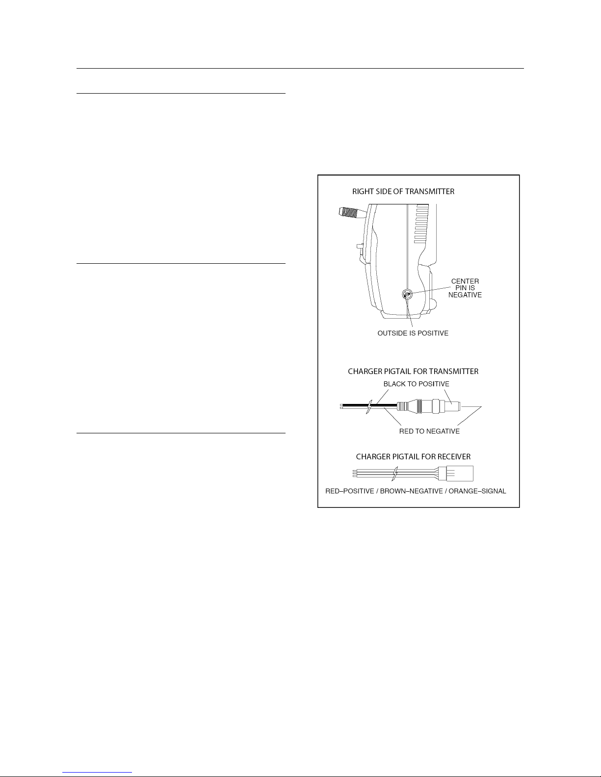
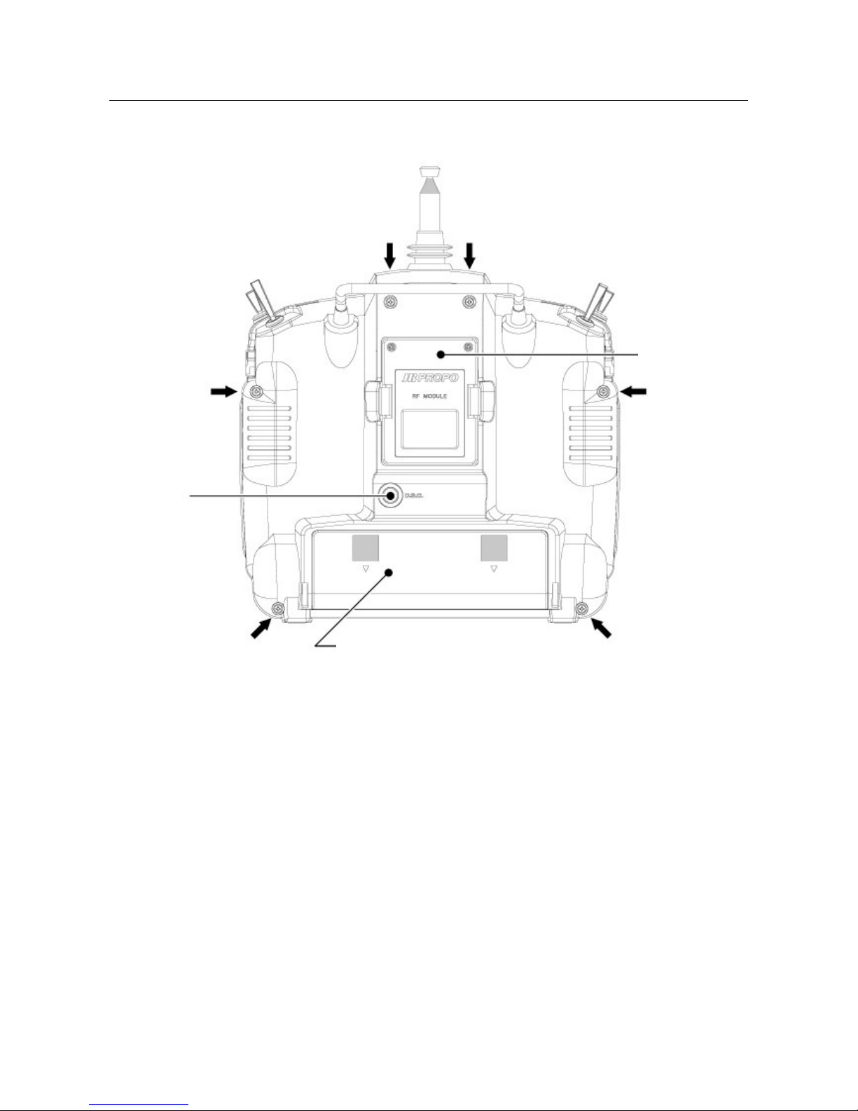
This receiver features Direct Servo Control (DSC) for
control of servos without radio frequency output.
The receiver has low current consumption.
The R770’s Slimline design allows it to fit into most
model applications.
R900 Receiver
R900 (Advanced Air, asic & Advanced
Helicopter Systems)
The R900 is a high-performance 9 channel PCM single-
conversion receiver with 10KHz super narrow band
ABC&W circuitry.
A narrow band ceramic filter for high-signal selectivity
assists in rejecting cross modulations from other
common radio frequencies, such as RC transmitters or
local paging systems.
This receiver features Direct Servo Control (DSC) for
control of servos without radio frequency output.
The receiver has low current consumption.
The R900’s credit card size design allows it to fit into
most model applications.