JRC JMA-5206 User manual

MARINE RADAR
MARINE RADAR
EQUIPMENT
EQUIPMENT
INSTRUCTION
INSTRUCTION
MANUAL
MANUAL
JMA-5206/HS
JMA-5206/HS
JMA-5210-4/6
JMA-5210-4/6
JMA-5220-7/9
JMA-5220-7/9
01ETM ISO 9001, ISO 14001 Certified
Printed in Japan
Marine Service Department
+81-3-3492-1305
+81-3-3779-1420
Telephone :
Facsimile :
e-mail :
AMSTERDAM Branch
Telephone :
Facsimile :
e-mail :
+31-20-658-0750
+31-20-658-0755
SEATTLE Branch
Telephone :
Facsimile :
e-mail :
+1-206-654-5644
+1-206-654-7030
CODE No.7ZPRD0652
CODE No.7ZPRD0652
MAY. 2007 Edition 3 JRC
Not use the asbestos
For further information,contact:
URL http://www.jrc.co.jp


◆◆◆PRECAUTIONS BEFORE OPERATION◆◆◆
■Cautions for high voltage
High voltages from hundreds volts to tens of thousands volts are to be applied to the electronic
equipment such radio and radar devices. You do not face any danger during normal operation,
but sufficient cares are required for maintenance, inspection and adjustment of their internal
components. (Maintenance, check-up and adjustment of the inside of the equipment are prohibited
except by maintenance specialists.)
High voltages of tens of thousands volts are so dangerous as to bring an instantaneous death from
electric shock, but even voltages of hundred volts may sometimes lead to a death from electric
shock. To prevent such an accident, make it a rule to turn off the power switch, discharge
capacitors with a wire surely earthed on an end make sure that internal parts are no longer charged
before you touch any parts inside these devices. At the time, wearing dry cotton gloves ensures
you further to prevent such danger. It is also a necessary caution to put one of your hands in the
pocket and not to use your both hands at the same time.
It is also important to select a stable foothold always to prevent additional injuries once you were
shocked by electricity. If you were injured from electric shock, disinfect the burn sufficiently
and get it taken care of promptly.
■What to do in case of electric shock
When finding a victim of electric shock, turn off the power source and earth the circuit
immediately.
If it is impossible to turn off the circuit, move the victim away promptly using insulators such as
dry wood plate and cloth without touching the victim directly.
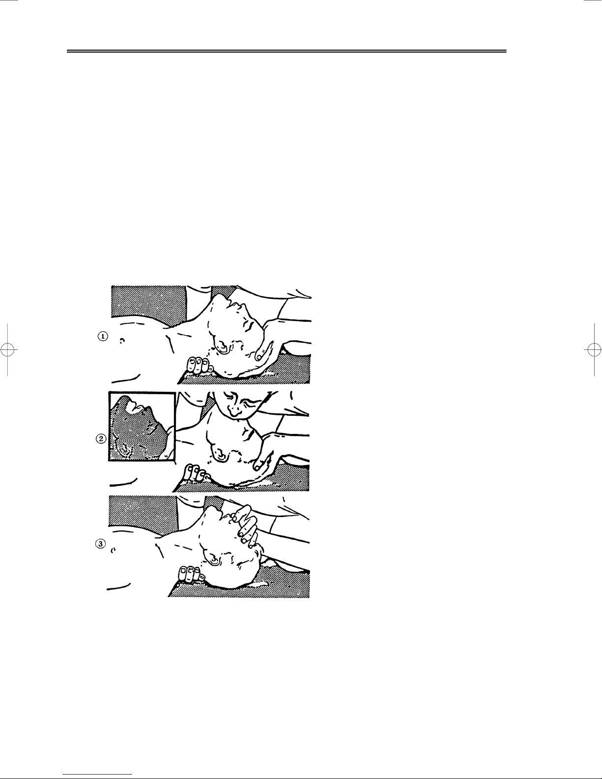
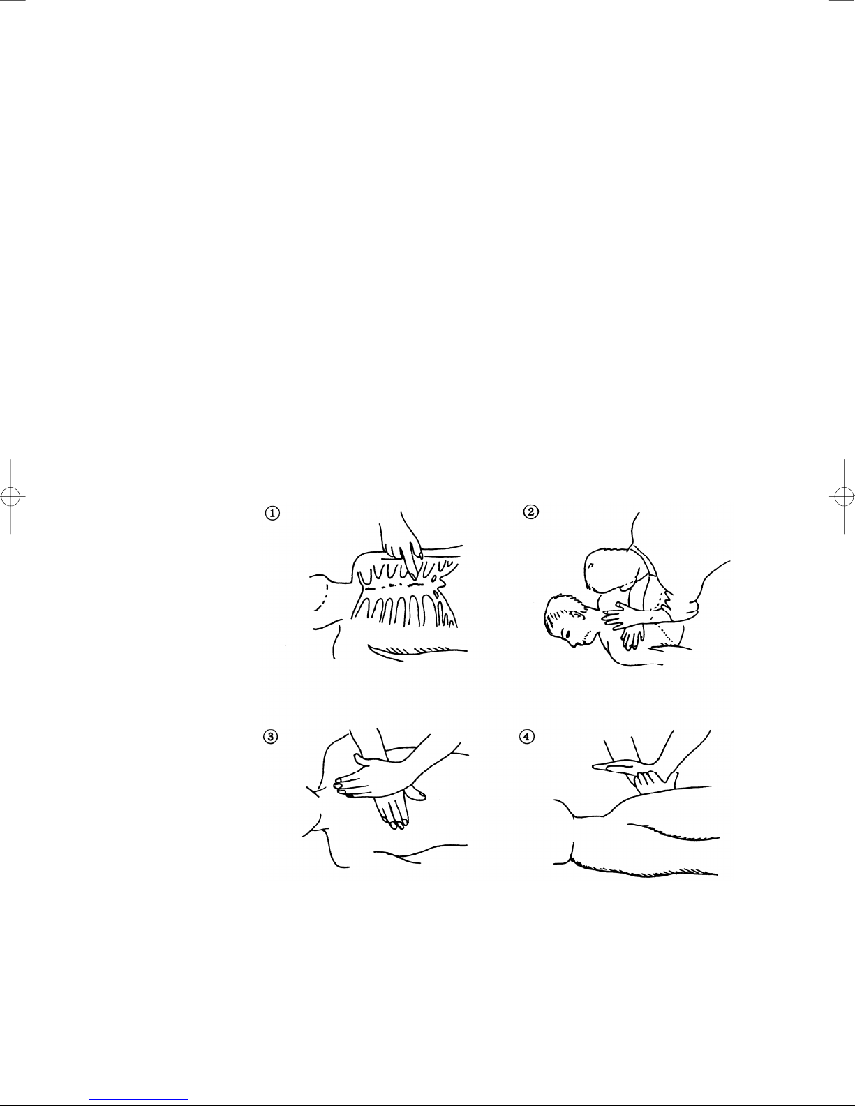
In case of electric shock, breathing may stop suddenly if current flows to the respiration center in
the brain. If the shock is not so strong, artificial respiration may recover breathing. When
shocked by electricity, the victim will come to look very bad with weak pulse or without beating,
resulting in unconsciousness and rigidity. In this case, it is necessary to perform an emergency
measure immediately.

◆◆◆FIRST-AID TREATMENTS◆◆◆
☆First-aid treatments
As far as the victim of electric shock is not in dangerous condition, do not move him and practice
artificial respiration on him immediately. Once started, it should be continued rhythmically.
(1) Do not touch the victim confusedly as a result of the accident, but the rescuer may also get an
electric shock.
(2) Turn off the power source calmly and move the victim away quietly from the electric line.
(3) Call a physician or ambulance immediately or ask someone to call a doctor.
(4) Lay the victim on this back and loosen his necktie, clothes, belt, etc.
(5) a. Examine the victim’s pulse.
b. Examine his heartbeat bringing your ear close to his heart.
c. Examine his breathing bringing the back of your hand or your face close to his face.
d. Check the size of the pupils of his eyes.
(6) Open the victim’s mouth and take out artificial teeth, cigarette or chewing gum if any.
Keep his mouth open, stretch his tongue and insert a towel or the like in his mouth to prevent
the tongue from suffocating. (If it is hard to open his mouth due to set teeth, open it with a
screwdriver and insert a towel in this mouth.)
(7) Then, wipe his mouth so that foaming mucus does not accumulate inside.

☆When pulse is beating but breathing has stopped
(Mouth-to-mouth respiration) Fig. 1
(1) Tilt the victim’s head back as far as this face looks back. (A pillow may be inserted his neck.)
(2) Push his jaw upward to open his throat wide (to spread his airway).
(3) Pinch the victim’s nostrils and take a deep breath, block his mouth completely with yours
and blow into his mouth strongly. Take a deep breath again and blow into his mouth.
Continue this 10 to 15 times a minutes (blocking his nostrils).
(4) Carefully watch that he has recovered his natural breathing and atop practicing artificial
respiration.
(5) If it is difficult to open the victim’s mouth, insert a rubber or vinyl tube into one of his
nostrils and blow into it blocking the other nostril and his mouth completely.
(6) When the victim recovers consciousness, he may try to stand up suddenly, but let him lie
calmly and serve him with a cup of hot coffee or tea and keep him warm and quiet. (Never
give him alcoholic drinks.)
Method of mouth-to-mouth respiration by raising head
(1) Raise the victim’s head. Support his
forehead with one of your hand and his
neck with the other hand. →1
When you tilt his head backward, the
victim, in most cases, opens his mouth to
the air. This makes mouth-to mouth
respiration easy.
(2) Cover his mouth as widely as possible with
yours and press your cheek against his nose
→2
or, pinch his nostrils with your fingers to
prevent air from leaking. →3
(3) Blow into his lungs. Continue blowing
into his mouth until his breast swells.
Blow into his mouth as quickly as possible
for the first 10 times.
Fig. 1 Mouth-to mouth respiration

☆When both pulse and breathing have stopped
Perform the (Cardiac massage) Fig. 2 and (Mouth-to-mouth respiration) Fig. 1
When no pulse has come not to be felt, his pupils are open and no heartbeat is heard, cardiac arrest
is supposed to have occurred and artificial respiration must be performed.
(1) Place your both hands, one hand on the other, on the lower one third area of his breastbone
and compress his breast with your elbows applying your weight on his breast so that it is
dented about 2cm (Repeat compressing his breast 50 times or so a minutes). (Cardiac
massage)
(2) In case of one rescuer,
Repeat cardiac massages about 15 times and blow into his mouth 2 times quickly, and repeat
this combination.
In case of two rescuers,
One person repeats cardiac massages 15 times while the other person blow into his mouth
twice, and they shall repeat this combination. (Perform the cardiac massage and
mouth-to-mouth respiration)
(3) Examine his pupils and his pulse sometimes. When the both have returned to normal, stop
the artificial respiration, serve him with a cup of hot coffee or tea and keep him warm and
calm while watching him carefully. Commit the victim to a medical specialist depending
on his condition. (Never give him alcoholic drinks.) To let him recover from the mental
shock, it is necessary for persons concerned to understand his situations and the necessary
treatment.
Fig. 2 Cardiac massage

- i -
PREFACE
Thank you very much for purchasing the JRC marine radar equipment, JMA-5200 series.
This equipment is a marine radar equipment designed to obtain safe operation of marine ships.
This equipment consists of a radar signal transmitter-receiver unit, a LCD display unit and a scanner unit as its
main units.
● Before operating the equipment, be sure to read this instruction manual carefully for correct operation.
● Maintain this instruction manual so that operators can refer to it at anytime.
Refer to this manual when any inconvenience or defect occurs.

- ii -
●Before Operation●
Pictorial Indication
Various pictorial indications are included in this manual and are shown on these equipment so that you can
operate them safety and correctly and prevent any danger to you and/or to other persons and any damage to
your property during operation. Such indications and their meanings are as follows.
Please understand them before you read this manual:
DANGER This indication is shown where incorrect equipment operation due to
negligence may cause death or serious injuries.
WARNING This indication is shown where any person is supposed to be in
danger of being killed or seriously injured if this indication is
neglected and these equipment are not operated correctly.
CAUTION This indication is shown where any person is supposed to be injured
or any property damage is supposed to occur if this indication is
neglected and these equipment are not operated correctly.
Examples of Pictorial Indication
Electric Shock
The Umark represents CAUTION (including DANGER and WARNING).
Detailed contents of CAUTION (“Electric Shock” in the example on the
left.) is shown in the mark.
Disassembling
Prohibited
Prohibited
The ;mark represents prohibition.
Detailed contents of the prohibited action (“Disassembling Prohibited” in the
example on the left.) is shown in the mark.
Disconnect
the power
plug
Instruction
The zmark represents instruction.
Detailed contents of the instruction (“Disconnect the power plug “ in the
example on the left.) is shown in the mark.
Warning Label
There is a warning label on the top cover of the equipment.
Do not try to remove, break or modify the label.

- iii -
Never conduct inspection or repair work of equipment
components.
Inspection or repair work by uncertified personnel may
result in fire hazard or electrocution.
For inspection and repair work of equipment
components, consult with our branch office, branch
shop, sales office, or our distributor in your district.
When conducting maintenance, make sure to turn the
main power off.
Failure to comply may result in electrocution.
Turn off the main power before cleaning the equipment.
Especially when a rectifier is used, make sure to turn it
off since voltage is still outputted from the rectifier even
after the indicator and the radar are turned off. Failure to
comply may result in equipment failure, or death or
serious injury due to electric shock.
When conducting maintenance work on the antenna,
make sure to turn its main power off.
Failure to comply may result in electrocution or injuries.
●PRECAUTIONS●
DANGER

- iv -
DANGER
Make sure to turn off the antenna operation switch.
Failure to comply may result in injuries caused by
physical contact with the rotating antenna.
WARNING
Never directly touch the internal components of the
antenna, receiver/transceiver, or indicator. Direct
contact with these high-voltage components may cause
electrocution. For maintenance, inspection, or
adjustment of equipment components, consult with our
branch office, branch shop, sales office, or our distributor
in your district.
To contact our sales department, branch offices, branch
shops, and sales offices:
Please refer to the "Office List" at the end of the
document.
Do not get close to the radiant section of the antenna. It
is a rotating part, and it may cause injuries if it suddenly
starts rotating and consequently hits the body. It is
recommended that the radiant section be installed at a
high place such as on the roof of the wheelhouse, on the
flying bridge, on the trestle, or on the radar mast so that
no one can get close to it. When any work must be done
on the antenna, make sure to turn the antenna switch off.

- v -
WARNING
About radiation from the antenna:
Never stare at the antenna from a distance closer than
that specified below for each type of antenna when it is
emitting radiation. Being within the specified distance
from the center of the front face of the antenna may
cause radiation exposure which could result in injuries
(especially of the eyes).
NKE-2102/2252 ( radio-density : 10 W/m2): 0.6 m
Make sure to install the antenna at a place higher than
human height.
Direct exposure to electromagnetic waves at close range
will have adverse effects on the human body.
Direct exposure to electromagnetic waves at close range
will have adverse effects on the human body. When it is
necessary to get close to the antenna for maintenance or
inspection purposes, make sure to turn the indicator
power switch to "OFF" or "STBY."
Direct exposure to electromagnetic waves at close range
will have adverse effects on the human body.
When conducting maintenance work, make sure to turn
off the power and unplug the power connector J1 of the
processor so that the power supply to the equipment is
completely cut off.
Some equipment components can carry electrical current
even after the power switch is turned off, and conducting
maintenance work without unplugging the power
connector may result in electrocution, equipment failure,
or accidents.

- vi -
CAUTION
Use the radar only as a navigation aid. The final
navigation decision must always be made by the operator
him/herself. Making the final navigation decision based
only on the radar display may cause accidents such as
collisions or running aground.
WARNING
When cleaning the display screen, do not wipe it too
strongly with a dry cloth. Also, do not use gasoline or
thinner to clean the screen. Failure to comply will result
in damage to the screen surface.
When disposing of used lithium batteries, be sure to
insulate the batteries by attaching a piece of adhesive
tape on the ⊕and {terminals. Failure to comply may
cause heat generation, explosion, or fire when the
batteries get shorted out.
Do not change MBS Level/Area unless absolutely
necessary.
Incorrect adjustment will result in deletion of nearby
target images and thus collisions may occur resulting in
death or serious injuries.

- vii -
CAUTION
Use ATA only as a navigation aid. The final navigation
decision must always be made by the operator
him/herself. Making the final navigation decision based
only on ATA information may cause accidents.
ATA information such as vector, target numerical data,
and alarms may contain some errors. Also, targets that
are not detected by the radar cannot be acquired or
tracked.
Making the final navigation decision based only on the
radar display may cause accidents such as collisions or
running aground.
When using the [AUTO SEA] function, never set the
suppression level too high canceling out all image noises
from the sea surface at close range.
Detection of not only echoes from waves but also targets
such as other ships or dangerous objects will become
inhibited.
When using the [AUTO SEA] function, make sure to
choose the most appropriate image noise suppression
level.
When using the [AUTO RAIN] function, never set the
suppression level too high canceling out all image noises
from the rain or snow at close range.
Detection of not only echoes from the rain or snow but
also targets such as other ships or dangerous objects will
become inhibited.
When using the [AUTO RAIN] function, make sure to
choose the most appropriate image noise suppression
level.
A malfunction may occur if the power in the ship is
instantaneously interrupted during operation of the
radar. In this case, the power should be turned on
again.

- viii -
CAUTION
When setting a guard zone, make sure to properly adjust
gain, sea-surface reflection suppression level, and
rain/snow reflection suppression level so that the optimal
target images are always on the radar screen. The guard
zone alarm will not be activated for targets undetected by
the radar, and it may result in accidents such as
collisions.
The simulation function is used exclusively for deciding
whether or not ATA is properly operating. Therefore,
never use this function unless you wish to check ATA
operations.
Note especially that, if this function is used during actual
navigation, simulated targets are displayed and may
become confused with other actual targets. Therefore,
never use this function during actual navigation.
Optimal values have been set for VD LEVEL and
CONSTANT; therefore, never change their values unless
absolutely necessary. Failure to comply may result in
accidents that would lower ATA performance.
Make sure to shut off the main power before replacing
parts. Failure to comply may result in electrocution or
equipment failure.
When replacing magnetrons, make sure to shut off the
main power and let the equipment stand for more than 5
minutes to discharge the high-voltage circuit. Failure to
comply may result in electrocution.

- ix -
CAUTION
Make sure to take off your watch when your hand must
get close to the magnetron.
Failure to comply may result in damage to the watch
since the magnetron is a strong magnet.
Make sure that two or more staff member work together
when replacing the LCD. If only one person attempts to
replace the LCD, he/she may drop it and become injured.
Do not directly touch the inverter circuit of the LCD
display with a bare hand since high voltage temporarily
remains in the circuit even after the main power is shut
off.
Failure to comply may result in electrocution.
Any adjustments must be made by specialized service
personnel.
Incorrect settings may result in unstable operation.
Do not make any adjustments during navigation. Failure
to comply may result in adverse effects on the radar
function which may lead to accidents or equipment
failure.
Any adjustments must be made by specialized service
personnel.
Failure to comply may result in accidents or equipment
failure.
Do not make any adjustments during navigation. Failure
to comply may result in adverse effects on the radar
function which may lead to accidents or equipment
failure.

- x -
CAUTION
Do not change the quantization level settings unless
absolutely necessary. If set at an inappropriate value,
the acquisition or tracking function of ATA deteriorates,
and this may lead to accidents.

- xi -
EQUIPMENT APPEARANCE
Scanner Unit Type NKE-2064/HS (4 feet)
Scanner Unit Type NKE-2102-4 (4 feet)
Scanner Unit Type NKE-2102-6 (6 feet)
Scanner Unit Type NKE-2252-7 (7 feet)

- xii -
Scanner Unit Type NKE-2252-9 (9 feet)
NDC-1340 Processor Unit (Desktop Type)
NWZ-164 Display Unit (Desktop Type)
NCE-7699 Operation Unit (Desktop Type)
NCD-4340 Display Unit (Desktop Type)

- xiii -
CONTENTS
PREFACE................................................................................................................i
BEFORE OPERATION ........................................................................................... ii
PRECAUTIONS..................................................................................................... iii
EQUIPMENT APPEARANCE ................................................................................ xi
GLOSSARY.......................................................................................................... xx
1. GENERAL AND EQUIPMENT COMPOSITION
1.1 FUNCTIONS........................................................................................... 1-1
1.1.1 FUNCTION OF THIS SYSTEM ........................................................ 1-1
1.2 FEATURES............................................................................................. 1-2
1.3 CONFIGURATION.................................................................................. 1-4
1.4 EXTERIOR DRAWINGS......................................................................... 1-5
1.5 GENERAL SYSTEM DIAGRAMS ......................................................... 1-15
2. NAMES AND FUNCTIONS OF CONTROL PANEL KEYS
AND FUNCTIONS OF SOFTWARE BUTTONS
2.1 NAMES AND FUNCTIONS OF CONTROL PANEL KEYS...................... 2-1
2.2 FUNCTIONS OF SOFTWARE BUTTONS.............................................. 2-7
3. BASIC OPERATION
3.1 FLOW OPERATION................................................................................ 3-1
3.1.1 POWER ON AND START THE SYSTEM ......................................... 3-2
3.1.2 OBSERVE AND ADJUST VIDEO ..................................................... 3-3
3.1.3 ACQUIRE AND MEASURE DATA .................................................... 3-3
3.1.4 END THE OPERATION AND STOP THE SYSTEM ......................... 3-4
3.2 MENU COMPOSITION........................................................................... 3-5
3.2.1 OVERVIEW OF MENU STRUCTURE.............................................. 3-5
3.2.2 BASIC MENU OPERATION ............................................................. 3-6

- xiv -
3.3 PREPARATION .......................................................................................3-8
3.3.1 ADJUST DISPLAY BRILLIANCE.......................................................3-8
3.3.2 ADJUST CONTRAST .......................................................................3-8
3.3.3 ADJUST OPERATION PANEL BRILLIANCE [PANEL]......................3-9
3.3.4 SWITCH DAY/NIGHT MODE [DAY/NIGHT]......................................3-9
3.3.5 ADJUST BRILLIANCE OF INFORMATION ON RADAR DISPLAY
(BRILLIANCE SETTING) ................................................................3-10
3.3.6 ADJUST SOUND VOLUME (BUZZER VOLUME) .......................... 3-11
3.3.7 RESET ALARM BUZZER [ALARM ACK] ........................................ 3-11
3.3.8 SET DISPLAY COLOR....................................................................3-12
3.4 BASIC OPERATIONS ...........................................................................3-14
3.4.1 START TRANSMISSION [TX/PRF].................................................3-14
3.4.2 STOP TRANSMISSION [STBY] ......................................................3-14
3.4.3 CHANGE RANGE (OBSERVATION RANGE SCALE)
[RANGE+/-] .....................................................................................3-14
3.4.4 TUNE ..............................................................................................3-15
3.4.5 CONTROL SENSITIVITY [GAIN/PL]...............................................3-15
3.4.6 SUPPRESS SEA CLUTTER [AUTO-SEA] ......................................3-16
3.4.7 SUPPRESS RAIN/SNOW CLUTTER [AUTO-RAIN].......................3-18
3.4.8 REJECT RADAR INTERFERENCE [IR] .........................................3-20
3.4.9 HIDE/DISPLAY RANGE RINGS (RINGS) .......................................3-21
3.4.10 HIDE SHIP’S HEADING LINE (HL OFF).........................................3-21
3.4.11 HIDE GRAPHICS INFORMATION ON RADAR DISPLAY
(GRAPHIC DISPLAY) .....................................................................3-22
3.5 GENERAL OPERATIONS .....................................................................3-23
3.5.1 MOVE CROSS CURSOR MARK BY TRACKBALL.........................3-23
3.5.2 USE EBLS (ELECTRONIC BEARING LINES) [EBL1/2] .................3-24
3.5.3 SET EBL OPERATION (EBL1 /2 SETTING) ...................................3-26
3.5.4 DISPLAY VARIABLE RANGE MARKERS [VRM1/VRM2]...............3-29
3.5.5 DISPLAY PARALLEL INDEX LINES (PARALLEL INDEX LINE) .....3-32
3.5.6 SWITCH BEARING DISPLAY MODE [AZI MODE] .........................3-40
3.5.7 SWITCH TRUE/RELATIVE MOTION DISPLAY MODE [TM/RM]....3-41
3.5.8 MOVE OWN SHIP’S DISPLAY POSITION [OFF CENT].................3-42
3.5.9 DISPLAY OTHER SHIPS’ TRAILS [TRAILS] ..................................3-43
3.5.10 SWITCH PULSE LENGTH (GAIN/PL) ............................................3-46
3.5.11 EXPAND TARGETS (TARGET ENHANCE) ....................................3-47
3.5.12 USE VIDEO PROCESS (PROCESS) .............................................3-48
3.5.13 ZOOM .............................................................................................3-49
3.5.14 USE MARKER [MOB] .....................................................................3-50
3.5.15 MARKING [MARK] ..........................................................................3-51
This manual suits for next models
5
Table of contents
Other JRC Marine Radar manuals

JRC
JRC JMA-5204 User manual

JRC
JRC JMR-9230-S User manual

JRC
JRC JMA-9102-CA User manual

JRC
JRC JMA-5912-6 User manual

JRC
JRC JMA-3300 Series User manual

JRC
JRC JMA-5212-4/6 User manual

JRC
JRC JMR-5410-6X User manual

JRC
JRC JMA-5322-6HS User manual

JRC
JRC JMA-7133-SA User manual

JRC
JRC JMA-9900 Series User manual