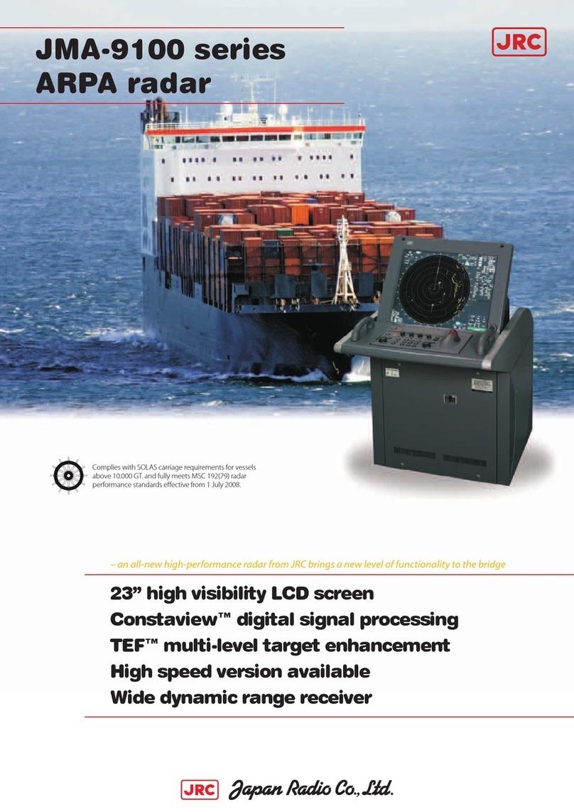
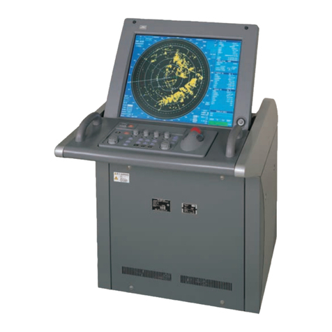
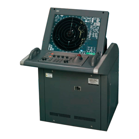
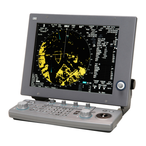
JRC JMR-7296-6X User manual

Overview
1
Name and Function of Each Unit
2
Common Basic Operations
3
Range and Bearing Measurement Methods
4
Basic Operation of the Radar
5
Target Tracking and AIS
6
True and False Echoes on Display
7
Functions of the ECDIS (Option)
8
Route Planning
9
Route Monitoring
10
Monitoring a Dragging Anchor
11
Automatic Sailing (Option)
12
Operating a Chart (Option)
13
Creating a User Chart/ Updating a Chart
Manually
14
Logbook
15
Setting Up Screen View
16
Setting Up Alerts
17
Setting Up the Operation Mode
18
Adjusting and Setting Up Equipment (for
Services)
19
Playing Back Data Recorded During
Navigation [Playback]
20
Maintenance & Inspection
21
Failures and After-Sale Services
22
About Disposal
23
Specifications
24
Radar Antenna Block Diagrams
APP A
Alert List
APP B
Setting the Interswitch
APP C
Menu List and Materials
APP D
JMR-7230-S3/S
JMR-7225-7X3/9X3/6X/9X/6XH
JMR-7210-6X/6XH
JMR-7272-S
JMR-7282-S/SH
JMR-7296-6X/9X
JMR-9230-S3/S
JMR-9225-7X3/9X3/6X/9X/6XH
JMR-9210-6X/6XH
JMR-9272-S
JMR-9282-S/SH
JMR-9296-6X/9X
Marine Radar Equipment
Instruction Manual
<Reference>


㻌
㻌
㻌(1) Contents
2
3
4
5
6
7
8
9
10
11
12
13
14
15
16
17
18
19
20
21
22
23
24
25
26
27
Section 19 Adjusting and Setting up Equipment (for Services)....................... 19-1
19.1 Service Menu ...................................................................................................................... 19-1
19.1.1 To display the Service menu:...................................................................................... 19-1
19.2 Radar Adjustment................................................................................................................ 19-3
19.2.1 Displaying the [Adjustment] dialog box....................................................................... 19-3
19.2.2 Performing basic adjustments on the radar................................................................ 19-4
19.2.2.1 Displaying the "Basic Adjustment" dialog ............................................................. 19-4
19.2.2.2 Tune adjustment ................................................................................................... 19-5
19.2.2.3 Adjusting the bearing............................................................................................ 19-5
19.2.2.4 Adjusting a distance ............................................................................................. 19-6
19.2.2.5 Radar operation modes ........................................................................................ 19-6
19.2.3 Adjusting Antenna....................................................................................................... 19-7
19.2.3.1 Displaying the [TXRX] dialog................................................................................ 19-7
19.2.3.2 Adjusting an radar antenna height ....................................................................... 19-7
19.2.3.3 Setting a tuning bar peak value............................................................................ 19-8
19.2.3.4 Adjusting a tuning peak value .............................................................................. 19-8
19.2.3.5 Setting bearing pulse output................................................................................. 19-8
19.2.4 Adjusting a radar performance monitor (Radar screen only) ..................................... 19-9
19.2.4.1 Displaying the [Performance Monitor]/[Performance Monitor (SSR)] dialog........ 19-9
19.2.4.2 Adjusting a magnetron radar performance monitor............................................ 19-10
19.2.4.3 Adjusting a performance monitor of a Solid State Radar (SSR) ........................ 19-11
19.2.5 Setting Sector Blank (Radar screen only) ................................................................ 19-13
19.2.5.1 Displaying the [Sector Blank] dialog................................................................... 19-13
19.2.5.2 Setting Sector Blank ........................................................................................... 19-13
19.2.6 Adjusting the TT function .......................................................................................... 19-14
19.2.6.1 Displaying the [TT] dialog ................................................................................... 19-14
19.2.6.2 Setting vector constants ..................................................................................... 19-15
19.2.6.3 Setting a quantization level at manual acquisition ............................................. 19-15
19.2.6.4 Setting a quantization level at automatic acquisition.......................................... 19-15
19.2.6.5 Setting a gate size used for tracking .................................................................. 19-16
19.2.6.6 Displaying a TT limit ring .................................................................................... 19-16
19.2.7 Adjusting MBS .......................................................................................................... 19-16
19.2.7.1 Displaying the [MBS] dialog................................................................................ 19-17
19.2.7.2 Performing MBS adjustment............................................................................... 19-17
19.2.7.3 Adjusting a MBS application range .................................................................... 19-17
19.3 Verifying Installation and Initial Setting ............................................................................. 19-18
19.3.1 Displaying the [Installation] dialog box...................................................................... 19-18
19.3.2 Verifying/Setting CCRP (Consistent Common Reference Point).............................. 19-19
19.3.2.1 Displaying the [CCRP] dialog ............................................................................. 19-19
19.3.2.2 Setting CCRP ..................................................................................................... 19-20
19.3.3 Setting a Serial Port.................................................................................................. 19-21
19.3.3.1 Displaying the [Serial Port] dialog ...................................................................... 19-22
7ZPNA4448
K

Contents (2)
19.3.3.2 [Diagnosis] lamp light colors............................................................................... 19-22
19.3.3.3 Setting a serial port............................................................................................. 19-22
19.3.3.4 To change the communication settings of the Serial Port .................................. 19-25
19.3.4 Setting a System Function........................................................................................ 19-28
19.3.4.1 Displaying a [System Function] dialog ............................................................... 19-28
19.3.4.2 Lamp light colors ................................................................................................ 19-28
19.3.4.3 Setting a system function ................................................................................... 19-29
19.3.5 Setting own ship's parameters.................................................................................. 19-35
19.3.5.1 Displaying the [Ship's Parameters] dialog.......................................................... 19-35
19.3.5.2 Setting own ship's parameters ........................................................................... 19-35
19.3.6 Setting the automatic sailing system ........................................................................ 19-36
19.3.6.1 Displaying the [Autosail] dialog .......................................................................... 19-36
19.3.6.2 Setting the automatic sailing system .................................................................. 19-37
19.3.7 Setting the AIS password.......................................................................................... 19-37
19.3.7.1 Displaying the [AIS] dialog.................................................................................. 19-37
19.3.7.2 Setting the AIS password ................................................................................... 19-38
19.3.8 Setting Sensor .......................................................................................................... 19-39
19.3.8.1 Displaying the [Sensor] dialog............................................................................ 19-39
19.3.8.2 Displaying an alert set point ............................................................................... 19-39
19.3.8.3 Setting the GPS switching linkage function........................................................ 19-40
19.3.9 Setting Route Sharing............................................................................................... 19-41
19.3.9.1 Displaying the [Route Sharing] dialog ................................................................ 19-41
19.3.9.2 Selecting a route sharing method....................................................................... 19-41
19.3.10 Setting the GPS Shared Route................................................................................. 19-42
19.3.10.1
Displaying the [GPS Shared Route] dialog........................................................ 19-42
19.3.10.2
Setting the GPS Shared Route.......................................................................... 19-42
19.3.11 Setting the Route Plan Exchange............................................................................. 19-44
19.3.11.1
Displaying the [Route Plan Exchange] dialog ................................................... 19-44
19.3.11.2
Setting the Route Plan Exchange...................................................................... 19-44
19.4 Maintenance...................................................................................................................... 19-45
19.4.1 Displaying the [Maintenance] dialog box .................................................................. 19-45
19.4.2 Managing storage ..................................................................................................... 19-46
19.4.3 Maintaining the radar (Radar screen only) ............................................................... 19-47
19.4.3.1 Displaying the [RADAR] dialog........................................................................... 19-47
19.4.3.2 Changing the operation mode of the safety switch ............................................ 19-47
19.4.3.3 Clearing a radar antenna operation time............................................................ 19-48
19.4.3.4 Replacing a TXRX circuit of a radar antenna ..................................................... 19-48
Section 20 Playing Back Data Recorded During Navigation........................... 20-1
20.1 Playback Controller ............................................................................................................. 20-3
20.2 Selecting Playback Data ..................................................................................................... 20-6
20.2.1 Sorting the Playback List ............................................................................................ 20-6
20.3 Playing back Logbook Data ................................................................................................ 20-7

(3) Contents
2
3
4
5
6
7
8
9
10
11
12
13
14
15
16
17
18
19
20
21
22
23
24
25
26
27
20.3.1 Changing the Playback Speed ................................................................................... 20-8
20.4 Exiting the Playback Mode.................................................................................................. 20-9
20.5 Outputting Navigation Record Data .................................................................................. 20-10
20.6 Functional Restrictions when in the Playback Mode ........................................................ 20-12
Section 21 Maintenance & Inspection............................................................. 21-1
21.1 Maintenance Functions Executed from Menu..................................................................... 21-1
21.1.1 Starting maintenance functions .................................................................................. 21-1
21.1.2 Setting Date/Time/Time Zone ..................................................................................... 21-1
21.1.3 Confirming System Information .................................................................................. 21-3
21.1.3.1 Confirming software information........................................................................... 21-4
21.1.3.2 Checking the enable/disable statuses of the functions that have been installed . 21-6
21.1.3.3 Confirming H/W key information........................................................................... 21-9
21.1.3.4 Confirming the compliant standards for the equipment...................................... 21-11
21.1.4 Confirming Operating Time....................................................................................... 21-13
21.1.5 Displaying/Resetting the Current Voyage Distance.................................................. 21-14
21.1.6 Setting and confirming the Sensor Source ............................................................... 21-16
21.1.7 Checking the Route Plan Exchange Log.................................................................. 21-19
21.2 General Maintenance........................................................................................................ 21-20
21.3 Maintenance on Each Unit................................................................................................ 21-21
21.3.1 Radar antenna NKE-1125/A、1129、1130/A、1139、1696......................................... 21-21
21.3.1.1 Precautions in mounting the cover..................................................................... 21-22
21.3.1.2 Radiator .............................................................................................................. 21-24
21.3.1.3 Rotating section.................................................................................................. 21-24
21.3.2 Flexible wave guide (JMR-9225-7X3/9X3, JMR-7225-7X3/9X3) ............................. 21-24
21.3.3 Coaxial cable (JMR-9230-S3, JMR-7230-S3) .......................................................... 21-25
21.3.4 Transmitter-receiver (NTG-3225/3230) .................................................................... 21-25
21.3.5 Display unit ............................................................................................................... 21-25
21.3.5.1 The Screen ......................................................................................................... 21-26
21.3.5.2 The Trackball ...................................................................................................... 21-26
21.4 Performance Check .......................................................................................................... 21-27
21.4.1 Starting Selftest functions ......................................................................................... 21-28
21.4.2 Confirming the screen status [Monitor Test] ............................................................. 21-29
21.4.3 Confirming the operation of the operation unit [Key Test]......................................... 21-33
21.4.4 Confirming the alert sound [Sound Test]................................................................... 21-34
21.4.5 Testing the brightness of LED [Light Test] ................................................................ 21-35
21.4.6 Checking the magnetron current level of the radar [Magnetron Curr.] ..................... 21-36
21.4.7 Checking the memory [Memory Check].................................................................... 21-37
21.4.8 Checking the performance monitor status................................................................ 21-38
21.4.8.1 MON Check ........................................................................................................ 21-39
21.4.8.2 MON Check (SSR) ............................................................................................. 21-41
21.4.9 Cleaning the lens of the DVD drive........................................................................... 21-42
21.5 Replacement of Major Parts.............................................................................................. 21-44
Contents (4)
21.5.1 Parts expected for periodic replacement .................................................................. 21-44
21.5.2 Replacement of magnetron ...................................................................................... 21-46
21.5.2.1 Handling of magnetron under long-time storage................................................ 21-46
21.5.2.2 Magnetron replacement procedure for radar antenna NKE-1130/A................... 21-47
21.5.2.3 Magnetron replacement procedure for radar antenna NKE-1125/A、
NKE-2254-HS..................................................................................................... 21-49
21.5.2.4 Magnetron replacement procedure for radar antenna NKE-2103、
NKE-2103HS ...................................................................................................... 21-51
21.5.2.5 Magnetron replacement procedure for transmitter-receiver unit NTG-3230 ...... 21-54
21.5.2.6 Magnetron replacement procedure for transmitter-receiver unit NTG-3225 ...... 21-56
21.5.3 Replacing the motor.................................................................................................. 21-59
21.5.3.1 Motor replacement procedure for radar antenna NKE-1130/A、NKE-1139 ........ 21-59
21.5.3.2 Motor replacement procedure for NKE-1632 ..................................................... 21-62
21.5.3.3 Motor replacement procedure for radar antenna NKE-2632/ NKE-2632-H ....... 21-64
21.5.3.4 Motor replacement procedure for radar antenna NKE-1125/A 、NKE-1129 、
NKE-1696 ........................................................................................................... 21-68
21.5.3.5 Motor replacement procedure for radar antenna NKE-2254-HS........................ 21-72
21.5.3.6 Motor replacement procedure for radar antenna NKE-2103、NKE-2103-HS .... 21-75
21.6 Software Update ............................................................................................................... 21-78
21.6.1 Local Update............................................................................................................. 21-78
21.6.2 Remote Update......................................................................................................... 21-81
21.7 Firmware Update............................................................................................................... 21-85
21.8 Updating Help Data........................................................................................................... 21-88
21.9 Confirming Maintenance INFO ......................................................................................... 21-91
21.9.1 Screen items/fields and their function....................................................................... 21-91
21.9.2 Switching to the standard window or the expanded window .................................... 21-94
21.9.3 Exporting maintenance information .......................................................................... 21-96
21.10 Data Backup/Restore........................................................................................................ 21-97
21.10.1 Backing up data ........................................................................................................ 21-97
21.10.2 Restoring backed up data......................................................................................... 21-99
21.11 Recovery of the Images in the C Drive ........................................................................... 21-101
21.11.1 Starting the equipment with the OS in the D drive.................................................. 21-102
21.11.2 Executing the SSD recovery tool ............................................................................ 21-102
21.11.3 Starting the equipment with the OS in the C drive (Software automatic recovery) 21-103
21.11.4 Re-setting C-MAP ................................................................................................... 21-104
Section 22 Failures and After-Sale Services................................................... 22-1
22.1 Failure Detection ................................................................................................................. 22-1
22.1.1 About alerts................................................................................................................. 22-1
22.1.2 Alert description .......................................................................................................... 22-1
22.1.3 S-57/63 chart related error message list..................................................................... 22-1
22.1.4 ARCS chart related error message list ....................................................................... 22-1
22.1.5 Fuse inspection........................................................................................................... 22-2

(5) Contents
2
3
4
5
6
7
8
9
10
11
12
13
14
15
16
17
18
19
20
21
22
23
24
25
26
27
22.2 Countermeasures for Failures ............................................................................................ 22-3
22.2.1 Special parts ............................................................................................................... 22-3
22.2.2 Repair circuit block...................................................................................................... 22-5
22.3 Troubleshooting................................................................................................................. 22-33
22.4 After-Sale Services ........................................................................................................... 22-48
22.4.1 About the retaining period of service parts ............................................................... 22-48
22.4.2 When requesting a repair ......................................................................................... 22-48
22.4.3 Recommendation of inspection and maintenance.................................................... 22-48
22.4.4 Extending the functions ............................................................................................ 22-50
22.4.4.1 Importing the license information ....................................................................... 22-50
Section 23 About Disposal.............................................................................. 23-1
23.1 About Disposal of This Equipment...................................................................................... 23-1
23.2 About Disposal of Used Magnetrons .................................................................................. 23-1
23.3 About Disposal of TR Tubes ............................................................................................... 23-1
23.4 Chinese Version RoHS ....................................................................................................... 23-2
Section 24 Specifications................................................................................ 24-1
24.1 JMR-9230-S3 ...................................................................................................................... 24-1
24.2 JMR-9230-S ........................................................................................................................ 24-2
24.3 JMR-9225-9X3 .................................................................................................................... 24-3
24.4 JMR-9225-7X3 .................................................................................................................... 24-4
24.5 JMR-9225-9X ...................................................................................................................... 24-5
24.6 JMR-9225-6X ...................................................................................................................... 24-6
24.7 JMR-9225-6XH ................................................................................................................... 24-7
24.8 JMR-9210-6X ...................................................................................................................... 24-8
24.9 JMR-9210-6XH ................................................................................................................... 24-9
24.10 JMR-9272-S ...................................................................................................................... 24-10
24.11 JMR-9282-S ...................................................................................................................... 24-11
24.12 JMR-9282-SH ................................................................................................................... 24-12
24.13 JMR-9296-9X .................................................................................................................... 24-13
24.14 JMR-9296-6X .................................................................................................................... 24-14
24.15 JMR-7230-S3 .................................................................................................................... 24-15
24.16 JMR-7230-S ...................................................................................................................... 24-16
24.17 JMR-7225-9X3 .................................................................................................................. 24-17
24.18 JMR-7225-7X3 .................................................................................................................. 24-18
24.19 JMR-7225-9X .................................................................................................................... 24-19
24.20 JMR-7225-6X .................................................................................................................... 24-20
24.21 JMR-7225-6XH ................................................................................................................. 24-21
24.22 JMR-7210-6X .................................................................................................................... 24-22
24.23 JMR-7210-6XH ................................................................................................................. 24-23

Contents (6)
24.24 JMR-7272-S ...................................................................................................................... 24-24
24.25 JMR-7282-S ...................................................................................................................... 24-25
24.26 JMR-7282-SH ................................................................................................................... 24-26
24.27 JMR-7296-9X .................................................................................................................... 24-27
24.28 JMR-7296-6X .................................................................................................................... 24-28
24.29 NKE-1139.......................................................................................................................... 24-29
24.30 NKE-1130/A....................................................................................................................... 24-30
24.31 NKE-1129.......................................................................................................................... 24-31
24.32 NKE-1125/A....................................................................................................................... 24-32
24.33 NKE-2254-6HS ................................................................................................................. 24-33
24.34 NKE-2103.......................................................................................................................... 24-34
24.35 NKE-1632.......................................................................................................................... 24-35
24.36 NKE-2632、NKE-2632-H................................................................................................... 24-36
24.37 NKE-1696.......................................................................................................................... 24-37
24.38 NTG-3230 ......................................................................................................................... 24-38
24.39 NTG-3225 ......................................................................................................................... 24-38
24.40 NJU-84 .............................................................................................................................. 24-39
24.41 NJU-85 .............................................................................................................................. 24-39
24.42 Display Unit ....................................................................................................................... 24-40
24.43 Target Tracking.................................................................................................................. 24-44
24.44 AIS..................................................................................................................................... 24-45

24.45 Central Control Unit........................................................................................................... 24-46
24.46 Power Supply Unit............................................................................................................. 24-47
24.47 Trackball Operation Unit ................................................................................................... 24-48
24.48 19inch Display (NWZ-207)................................................................................................ 24-48
24.49 19inch Display (NWZ-214)................................................................................................ 24-49
24.50 26inch Display................................................................................................................... 24-50
24.51 Keyboard OPU .................................................................................................................. 24-51
24.52 26inch Display Unit Mount Kit ........................................................................................... 24-51
24.53 19inch Display Unit Mount Kit ........................................................................................... 24-51
24.54 Sensor LAN Switch Unit.................................................................................................... 24-52
24.55 Junction Box...................................................................................................................... 24-53
Appendix A Radar Antenna Block Diagrams ......................................................A-1
A.1 NKE-1139 (110 VAC).............................................................................................................A-1
A.2 NKE-1139 (220 VAC) ............................................................................................................A-2
A.3 NTG-3230 .............................................................................................................................A-3
A.4 NKE-1130 (110 VAC).............................................................................................................A-4
A.5 NKE-1130 (220 VAC) ............................................................................................................A-5
A.6 NKE-1130A (110/220 VAC) ...................................................................................................A-6

(7) Contents
2
3
4
5
6
7
8
9
10
11
12
13
14
15
16
17
18
19
20
21
22
23
24
25
26
27
A.7 NKE-1632..............................................................................................................................A-7
A.8 NKE-2632/2632-H.................................................................................................................A-8
A.9 NKE-1129 (110 VAC).............................................................................................................A-9
A.10 NKE-1129 (220 VAC) ..........................................................................................................A-10
A.11 NTG-3225 ........................................................................................................................... A-11
A.12 NKE-1125 (110 VAC)...........................................................................................................A-12
A.13 NKE-1125 (220 VAC) ..........................................................................................................A-13
A.14 NKE-1125A (110/220 VAC) .................................................................................................A-14
A.15 NKE-2254/2254-6HS ..........................................................................................................A-15
A.16 NKE-2103/2103-6HS ..........................................................................................................A-16
A.17 NKE-1696............................................................................................................................A-17
Appendix B Alert, Maintenance INFO and Permanent information ....................B-1
B.1 Alert .......................................................................................................................................B-1
B.1.1 Priority: Alarms..............................................................................................................B-2
B.1.2 Priority: Warnings..........................................................................................................B-3
B.1.3 Priority: Cautions.........................................................................................................B-10
B.1.4 List of Alert escalation.................................................................................................B-16
B.1.5 List of Alerts with responsibility-transferred state .......................................................B-17
B.1.6 List of Aggregated Alerts .............................................................................................B-18
B.1.7 List of Alert Icons.........................................................................................................B-21
B.2 Maintenance INFO ..............................................................................................................B-22
B.3 Permanent Information........................................................................................................B-72
Appendix C Setting the Inter switch....................................................................C-1
C.1 Overview .............................................................................................................................. C-1
C.1.1 Overview ...................................................................................................................... C-1
C.1.2 Checking the connection status with the connected radar antennas .......................... C-2
C.2 Inter switch Operations ........................................................................................................ C-3
C.2.1 Flow of operations........................................................................................................ C-3
C.2.2 Opening the [Inter Switch] dialog box.......................................................................... C-4
C.2.3 Checking the connection pattern ................................................................................. C-6
C.2.3.1 About equipment defect mark ( ) and error notification mark ( ) ................. C-8
C.2.4 Changing the connection pattern................................................................................. C-9
C.2.5 Changing the name of radar antenna or display unit................................................. C-10
C.2.6 Using the set connection pattern ................................................................................C-11
C.3 Reference........................................................................................................................... C-14
C.3.1 Pre-heat time after changing the connection pattern................................................. C-14
C.3.2 Precautions while changing the connection pattern .................................................. C-14
C.3.3 Precautions during a slave connection...................................................................... C-14
C.3.4 Setting during installation........................................................................................... C-15
Appendix D Menu List and Materials..................................................................D-1

Contents (8)
D.1 Menu List.............................................................................................................................. D-1
D.1.1 Route Planning ............................................................................................................ D-1
D.1.2 Route Monitoring.......................................................................................................... D-3
D.1.3 Anchor Watch............................................................................................................... D-4
D.1.4 Autosail*....................................................................................................................... D-5
D.1.5 Chart ............................................................................................................................ D-6
D.1.6 User Chart.................................................................................................................... D-8
D.1.7 Logbook ....................................................................................................................... D-9
D.1.8 TT/AIS........................................................................................................................ D-10
D.1.9 Tools........................................................................................................................... D-13
D.1.10 View ........................................................................................................................... D-16
D.1.11 Alert............................................................................................................................ D-21
D.1.12 Settings ...................................................................................................................... D-22
D.1.13 Chart Maintenance..................................................................................................... D-28
D.1.14 Maintenance .............................................................................................................. D-30
D.1.15 Help............................................................................................................................ D-33
D.1.16 Code Input ................................................................................................................. D-34
D.1.17 Service ....................................................................................................................... D-35
D.2 Context Menu List .............................................................................................................. D-43
D.2.1 No object.................................................................................................................... D-43
D.2.1.1 ECDIS (S57/C-MAP) screen ............................................................................... D-43
D.2.1.2 ECDIS(ARCS) screen ......................................................................................... D-44
D.2.1.3 RADAR screen .................................................................................................... D-45
D.2.2 AIS D-46
D.2.2.1 Sleeping AIS target.............................................................................................. D-46
D.2.2.2 Activated AIS target ............................................................................................. D-47
D.2.2.3 Numeric displayed AIS target .............................................................................. D-48
D.2.3 TT D-49
D.2.3.1 Internal TT ........................................................................................................... D-49
D.2.3.2 External TT .......................................................................................................... D-49
D.2.3.3 TT detail information display (internal TT)........................................................... D-50
D.2.3.4 TT detail information display (external TT).......................................................... D-50
D.2.4 NAVTEX..................................................................................................................... D-51
D.2.4.1 NAVTEX............................................................................................................... D-51
D.2.5 Mariner's Mark/Line ................................................................................................... D-52
D.2.5.1 Event mark .......................................................................................................... D-52
D.2.5.2 Information mark.................................................................................................. D-52
D.2.5.3 Current mark........................................................................................................ D-52
D.2.5.4 Clearing line......................................................................................................... D-52
D.2.5.5 Highlighted display .............................................................................................. D-53
D.2.6 User chart .................................................................................................................. D-54
D.2.6.1 Symbol................................................................................................................. D-54
D.2.6.2 Simple line ........................................................................................................... D-54

(9) Contents
2
3
4
5
6
7
8
9
10
11
12
13
14
15
16
17
18
19
20
21
22
23
24
25
26
27
D.2.6.3 Line - Circle ......................................................................................................... D-54
D.2.6.4 Line - Ellipse ........................................................................................................ D-54
D.2.6.5 Arc ....................................................................................................................... D-55
D.2.6.6 Polygon................................................................................................................ D-55
D.2.6.7 Area - Circle......................................................................................................... D-55
D.2.6.8 Area - Ellipse ....................................................................................................... D-55
D.2.6.9 Fan....................................................................................................................... D-56
D.2.6.10 Text ...................................................................................................................... D-56
D.2.6.11 Arrow ................................................................................................................... D-56
D.2.7 Manual Update........................................................................................................... D-57
D.2.7.1 Symbol................................................................................................................. D-57
D.2.7.2 Simple line ........................................................................................................... D-57
D.2.7.3 Line - Circle ......................................................................................................... D-57
D.2.7.4 Line - Ellipse ........................................................................................................ D-57
D.2.7.5 Arc ....................................................................................................................... D-58
D.2.7.6 Polygon................................................................................................................ D-58
D.2.7.7 Area - Circle......................................................................................................... D-58
D.2.7.8 Area - Ellipse ....................................................................................................... D-58
D.2.7.9 Fan....................................................................................................................... D-59
D.2.7.10 Text ...................................................................................................................... D-59
D.2.7.11 Arrow ................................................................................................................... D-59
D.2.8 Manual Update(ARCS, C-MAP) ................................................................................ D-59
D.2.8.1 Objects that have not been saved....................................................................... D-59
D.2.8.2 Saved objects (hidden)........................................................................................ D-59
D.2.9 Monitored route.......................................................................................................... D-60
D.2.9.1 Monitored route ................................................................................................... D-60
D.2.10 Planned route............................................................................................................. D-61
D.2.10.1 Planned route ...................................................................................................... D-61
D.2.11 Monitoring dragging anchor ....................................................................................... D-62
D.2.11.1 Dragging anchor monitoring circle....................................................................... D-62
D.2.11.2 Dragging anchor monitoring polygon .................................................................. D-62
D.3 Abbreviations of Geodetic Data ......................................................................................... D-63
D.4 Lists of Terminologies, Units, and Abbreviations................................................................ D-65
D.5 Icon Button List for User Chart........................................................................................... D-74
D.6 Icon Button List for Manual Update (S-57)......................................................................... D-79
D.6.1 Symbol ....................................................................................................................... D-80
D.6.2 Line ............................................................................................................................ D-84
D.6.3 Area ........................................................................................................................... D-90
D.6.4 Tex t .......................................................................................................................... D-107
D.6.5 ENC object attributes............................................................................................... D-108
D.7
Manual Update Icon Button Lists (ARCS and C-MAP)
........................................................ D-121
D.7.1 Symbol ..................................................................................................................... D-122
D.7.2 Line .......................................................................................................................... D-143

Contents (10)
D.7.3 Area ......................................................................................................................... D-147
D.7.4 Tex t .......................................................................................................................... D-148
D.8 List of Navigation-related Symbols .................................................................................. D-149
D.8.1 Related to own ship symbols ................................................................................... D-149
D.8.2 TT/AIS related.......................................................................................................... D-151
D.8.3 Navigation monitoring related .................................................................................. D-152
D.8.4 Tool related .............................................................................................................. D-153
D.9 List of Icons/Icon Buttons ................................................................................................. D-155
D.10 Data Format of the File that can be Imported/Exported in the ECDIS............................. D-161
D.10.1 File Types................................................................................................................. D-161
D.10.2 File Name................................................................................................................. D-161
D.10.3 CSV File Data Structure .......................................................................................... D-161
D.10.4 Route File................................................................................................................. D-162
D.10.5 User Chart File......................................................................................................... D-165
D.10.6 Log Book File ........................................................................................................... D-183
Software License Agreement....................................................................................................... D-188
Font License Agreement.............................................................................................................. D-189
IPA Font License Agreement v1.0................................................................................................ D-190

19-1 Section 19 Adjusting and Setting up Equipment (for Services)
1
2
3
4
5
6
7
8
9
10
11
12
13
14
15
16
17
18
19
20
21
22
23
24
25
APP A
APP B
Section 19 Adjusting and Setting up
Equipment (for Services)
This section describes the methods for radar adjustment, installation verification, and maintenance that
are conducted by the service staff by using the Service menu at installation construction of this
equipment.
Never have the equipment adjusted by unauthorized service personnel.
If the equipment is set up incorrectly, it may cause unstable operation.
Further, an accident or trouble may occur.
Never make adjustments while sailing.
Doing so may adversely affect the radar functions, causing accidents
and/or malfunctions.
19.1 Service Menu
The Service menu consists of three submenus of Adjustment, Installation and Maintenance. To display
the Service menu, a password is required.
19.1.1 To display the Service menu:
1 Click on the [MENU] button on the left toolbar.
The menu is displayed.

Section 19 Adjusting and Setting up Equipment (for Services) 19-2
2 Change over to the second page using the page switching button, and click the [Code
Input] button.
The password input dialog is displayed.
3 Enter 0 in Password.
4 Click on the [MENU] button on the left toolbar.
The menu is displayed.
5 Change to the 2nd page by using the page change button.
The [Service] button is added
6 Click the [Service] button.
The submenu is displayed.
7 Display a submenu dialog box by clicking on one of the [Adjustment], [Installation],
and [Maintenance] buttons.

19-3 Section 19 Adjusting and Setting up Equipment (for Services)
1
2
3
4
5
6
7
8
9
10
11
12
13
14
15
16
17
18
19
20
21
22
23
24
25
APP A
APP B
19.2 Radar Adjustment
Use the [Adjustment] dialog box to adjust the radar of this equipment.
19.2.1 Displaying the [Adjustment] dialog box
Clicking the [Adjustment] button in the submenu displays the [Adjustment] dialog box.
The [Adjustment] dialog box consists of the classification pane and the edit pane.
By clicking the Disclosure button (>>) , you can hide the edit pane. To show the edit pane again, click
the Disclosure button (<<).
1 Click the item you want to set up in the classification pane.
The setup dialog of the item you selected appears in the edit pane.
2 Set up in the edit pane.
Note
On the ECDIS screen, [Performance Monitor] and [TT] do not function. Alternatively, the setting of
[Sector Blank] cannot be changed.
Disclosure button
Classification pane Edit pane
[Adjustment] dialog box

Section 19 Adjusting and Setting up Equipment (for Services) 19-4
19.2.2 Performing basic adjustments on the radar
Perform basic adjustments on the radar by using the [Basic Adjustment] dialog.
19.2.2.1 Displaying the "Basic Adjustment" dialog
When you select [Basic Adjustment] in the classification pane, the [Basic Adjustment] dialog is
displayed in the edit pane.

19-5 Section 19 Adjusting and Setting up Equipment (for Services)
1
2
3
4
5
6
7
8
9
10
11
12
13
14
15
16
17
18
19
20
21
22
23
24
25
APP A
APP B
19.2.2.2 Tune adjustment
Note
• After replacement of the magnetron, perform rough tuning while the image is stable after setting
the radar to the Standby state for 20 to 30 minutes as the preheating time, operating the radar
from the short pulse range, and shifting the operation to the long pulse range sequentially.
• This operation is disabled when the Radar Interswitch is set to the Slave mode.
• Not displayed when the solid-state radar antenna is connected.
1 Click on the [Tune Adjustment] (rough tuning) input box.
A numeric value input keyboard is displayed. (0 to 127)
2 Enter an adjustment value (0 to 127) in the input box so that the tuning bar indicates
the maximum level (the tuning bar touches the right-most position).
For the method of using the numeric input keyboard, refer to "3.16.2 Name and function of each
section of the keyboard".
19.2.2.3 Adjusting the bearing
Adjust the bearing so that the bearing of the target measured by the compass on the ship and the
bearing of the image that is displayed on the radar match.
Note
This function is disabled when the radar interswitch is set to the Slave mode.
1 Set the bearing mode to [H UP] and set the image processing mode to [Process Off].
For the bearing mode setting method, refer to "5.4.5 Setting the azimuth mode" and for the
image processing mode setting method, refer to "5.4.4 Using video processing (Echo
Process)".
2 Measure a bearing in the ship's heading direction of a suitable target (for instance,
halted ship, breakwater, and buoy) by using the compass on the ship.
3 Click on the [Bearing Adjustment] input box.
A numeric value input keyboard is displayed.
4 Input an adjustment value in the input box so that the bearing of the target that was
measured in Step 2 indicates a correct bearing. (0 to 359.9°)
For the method of using the numeric input keyboard, refer to "3.16.2 Name and function of each
section of the keyboard".

Section 19 Adjusting and Setting up Equipment (for Services) 19-6
19.2.2.4 Adjusting a distance
Adjust the distance of the target on the screen so that the correct distance is displayed.
1 On the radar screen, specify a target whose distance is available in advance.
2 Click on the [Range Adjustment] input box.
A numeric value input keyboard is displayed.
3 Enter an adjustment value in the input box so that the distance of the target specified
in Step 1 indicates the correct distance. (128 to 1024)
For the method of using the numeric input keyboard, refer to "3.16.2 Name and function of each
section of the keyboard".
19.2.2.5 Radar operation modes
Click one of the radar operation mode buttons to select either the [Master] mode or the [Slave] mode.
[Master]:
Can control the radar antenna.
[Slave]:
Cannot control the radar antenna. The display unit uses the radar signals controlled by the master
radar antenna.
Note
While in the Slave mode, the operation to control the radar antenna is disabled.

19-7 Section 19 Adjusting and Setting up Equipment (for Services)
1
2
3
4
5
6
7
8
9
10
11
12
13
14
15
16
17
18
19
20
21
22
23
24
25
APP A
APP B
19.2.3 Adjusting Antenna
Adjust the antenna by using the [TXRX] dialog.
19.2.3.1 Displaying the [TXRX] dialog
When you select [TXRX] in the classification pane, the [TXRX] dialog is displayed in the edit pane.
19.2.3.2 Adjusting an radar antenna height
1 Measure the height from the sea surface to the radar antenna.
2 In the [Antenna height] combo box, select the setting value corresponding to the
height of the antenna that was measured in step 1.
•Under 5m
•5-10m
•10-20m
•20m Over

Section 19 Adjusting and Setting up Equipment (for Services) 19-8
19.2.3.3 Setting a tuning bar peak value
Set the scale when the tuning bar touches the peak value.
Notes
• This function is disabled under radar slave mode.
• Not displayed when a solid-state radar antenna is connected.
• Disabled in ECDIS mode.
1 Set the range to 48 NM or more.
2 Click on the [Tune Indicator] (tune indicator bar display) input box.
A numeric value input keyboard is displayed.
3 Input a setting value in the input box so that the tuning bar oscillates within the range
from 80% to 90% of the maximum amplitude position (0 to 127).
For the method of using the numeric input keyboard, refer to "3.16.2 Name and function of each
section of the keyboard".
19.2.3.4 Adjusting a tuning peak value
Adjust a tuning indication and an echo peak.
Notes
• Disabled in radar slave mode.
• Displayed under 10kW radar (NKE-2103-6, NKE-2103-6HS) only.
1 Adjust the tuning indication bar as described in “19.2.3.3 Setting a tuning bar peak
value”.
2 Set the range to 48nm or more.
3 Click the [Tune Peak Adjustment] input box.
A numerical value input keyboard is displayed.
4 Adjust the tuning peak adjustment value so that the radar image becomes strongest
when the tuning indication at the top left corner of the screen points to the maximum.
For the method of using the numerical value input keyboard, refer to “3.16.2 Name and function
of each section of the keyboard”.
19.2.3.5 Setting bearing pulse output
Notes
Disabled in ECDIS mode.
1 From the [Output BP] (bearing pulse output) combo box, select a bearing pulse count
that is output from the radar antenna (2048 or 4096).
This manual suits for next models
28
Other JRC Marine Radar manuals

JRC
JRC JMA-5352-9R User manual

JRC
JRC JMA-7133-SA User manual

JRC
JRC JMA-5200MK2 - User manual

JRC
JRC JMR-5410-6XH User manual

JRC
JRC JMA-932B-SA User manual

JRC
JRC JMR-7230-S3 User guide

JRC
JRC JMR-5404-X User manual

JRC
JRC JMA-9110-6XA User manual

JRC
JRC JMA-9133-SA User manual

JRC
JRC JMA-9133-SA User manual

JRC
JRC JMA-3806 User manual

JRC
JRC JMA-5104 User manual

JRC
JRC JMA-922B-6XA User manual

JRC
JRC JMA-3400 Series User manual

JRC
JRC JMA-5312-6/6HS User manual

JRC
JRC JMA-7710-6 User manual

JRC
JRC JMA-9832-SA User manual

JRC
JRC JMR-9230-S User manual

JRC
JRC JMA-5212-4 User manual

JRC
JRC JMA-5300 Series User manual