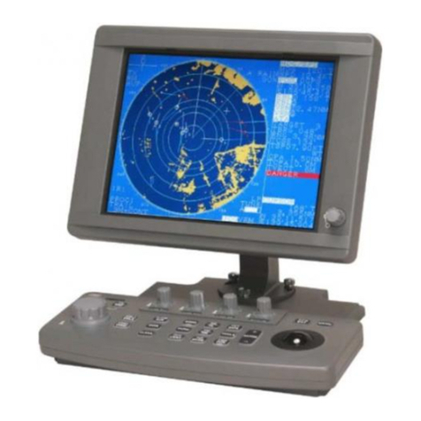
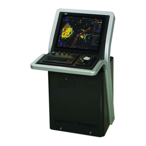
JRC JAN-701B - User manual

JAN-701B/901BJAN-701B/901B
INSTRUCTIONINSTRUCTION
MANUALMANUAL
ECDISECDIS


Cautions for High Voltage
High voltages, ranging from several hundreds to tens of thousands of volts, are used in
electronic apparatus, such as radio and radar instruments. These voltages are totally
harmless in most operations. However, touching a component inside the unit is very
dangerous. (Any person other than authorized service engineers should not service,
inspect, or adjust the unit.)
High voltages on the order of tens of thousand volts are most likely to cause instant
deaths from electrical shocks. At times, even voltages on the order of several hundred volts
could lead to electrocution. To defend against electrical shock hazards, don't put your hand
into the inside of apparatus. When you put in a hand unavoidably in case of urgent, it is
strongly suggested to turn off the power switch and allow the capacitors, etc. to discharge
with a wire having its one end positively grounded to remove residual charges. Before you
put your hand into the inside of apparatus, make sure that internal parts are no longer
charged. Extra protection is ensured by wearing dry cotton gloves at this time. Another
important precaution to observe is to keep one hand in your pocket at a time, instead of
using both hands at the same time.
It is also important to select a secure footing to work on, as the secondary effects of
electrical shock hazards can be more serious. In the event of electrical shocks, disinfect the
burnt site completely and obtain medical care immediately.
Precautions for Rescue of Victim of
Electric Shock
When a victim of electric shock is found, turn off the power source and ground the circuit
immediately. If this is impossible, move the victim away from the unit as quick as possible
without touching him or her with bare hands. He or she can safely be moved if an insulating
material such as dry wood plate or cloth is used.
Breathing may stop if current flows through the respiration center of brain due to electric
shock. If the electric shock is not large, breathing can be restored by artificial respiration. A
victim of electric shock looks pale and his or her pulse may become very weak or stop,
resulting in unconsciousness and rigidity at worst. It is necessary to perform first aid
immediately.
Method of First-Aid Treatment
☆Precautions for First-Aid Treatments
Whenever a person is struck by an electrical shock, give the patient artificial respiration
immediately on the spot, unless it is absolutely necessary to move the patient for safety's
sake. Once started, artificial respiration should be continued rhythmically.
(1) Refrain from touching the patient carelessly as a result of the accident; the first-aider
could suffer from electrical shocks by himself or herself.
(2) Turn off the power calmly and certainly, and move the patient apart from the cable
gently.
(3) Call or send for a physician or ambulance immediately, or ask someone to call doctor.
(4) Lay the patient on the back, loosening the necktie, clothes, belts and so on.
(5) (a) Feel the patient's pulse.
(b) Check the heartbeat by bringing your ear close to the patient's heart.
(c) Check for respiration by bringing your face or the back of your hand to the patient's
face.
(d) Check the size of patient's pupils.
(6) Opening the patient's mouth, remove artificial teeth, cigarettes, chewing gum, etc. if
any. With the patient's mouth open, stretch the tongue and insert a towel or the like into
the mouth to prevent the tongue from being withdrawn into the throat. (If the patient
clenches the teeth so tight that the mouth won't open, use a screwdriver or the like to
force the mouth open and then insert a towel or the like into the mouth.)
(7) Wipe off the mouth to prevent foaming mucus and saliva from accumulating.

☆Treatment to Give When the Patient Has a
Pulse Beating but Has Ceased to Breathe
*Performing mouth-to-mouth artificial respiration - Fig. 1
(1) Bend the patient's face backward until it is directed to look back. (A pillow may be
placed under the neck.)
(2) Pull up the lower jaw to open up the airway. (to spread the airway)
(3) Pinching the patient's nose, breathe deeply and blow your breath into the patient's
mouth strongly, with care to close it completely. Then, move your mouth away and
take a deep breath, and blow into his or her mouth. Repeat blowing at 10 to 15 times
a minute (always with the patient's nostrils closed).
(4) Continue artificial respiration until natural respiration is restored.
(5) If the patient's mouth won't open easily, insert a pipe, such as one made of rubber or
vinyl, into either nostril. Then, take a deep breath and blow into the nostril through
the pipe, with the other nostril and the mouth completely closed.
(6) The patient may stand up abruptly upon recovering consciousness. Keep the patient
lying calmly, giving him or her coffee, tea or any other hot drink (but not alcoholic
drink) to keep him or her warm.
Meouth-to-mouth artificial respiration with the patient's head lifted
①
(1) Lift the back part of the patient's
head. Support the forehead with one
of your hand and the neck with the
other hand.→①.
Many patients will have their airways
opened by lifting their head in this
way to ease mouth-to-mouth artificial
respiration.
②
(2) Closing the patient's mouth with your
mouth, press your cheek against the
patient's nose→②.
A
lternatively, hold the patient's nose
with your finger to prevent air leak
→③.
③(3) Blowing air into the patient's lungs.
Blow air into the patient's lungs until
chest is seen to rise. The first 10
breaths must be blown as fast as
possible.
Fig.1 Mouth-to-mouth artificial respiration

☆
Treatment to Give When the Patient Has No
Pulse Beating and Has Ceased to Breathe
*Performing cardiac massage - Fig. 2
If the patient has no pulse beating, with the pupils open and no heartbeat being heard,
the patient has a cardiac arrest and requires immediate artificial respiration. Continue
this until a medical specialist arrives, and follow his or her directions after that.
(1) Putting one hand on about the lower one third of the patient's ribs and the other hand
over the back of the first, with your elbow fully stretched (with bended elbow, you
can’t press to the extent the patient’s ribs are depressed), apply your body weight to
the hands to press the patient's body until it is depressed about 2 cm (Repeat this
about 50 times a minute). (Cardiac massage.)
(2) If only one first-aider is available, perform a cardiac massage about 15 times and
then give mouth-to-mouth artificial respiration 2 times. Repeat this sequence. If two
first-aiders are available, while one person performs a cardiac massage 15 times,
and the other should give mouth-to-mouth artificial respiration 2 times. Repeat this
sequence (combined cardiac massage and mouth-to-mouth artificial respiration
method).
(3) Check the patient's pupils and feel the pulse from time to time. When the pupils are
restored to normal and the pulse begins to beat regularly, stop treating and keep the
patient calm while giving him or her coffee, tea or any other hot drink to keep him or
her warm while watching him or her carefully.
Fig.2 Cardiac massage
①
③
②
④

v
PREFACE
Thank you for purchasing the JRC JAN-701B/901B ECDIS/Conning Display.
This equipment consists of ECDIS (Electronic Chart Display and Information
System) and Conning Display.
This ECDIS meets the performance standards of the IMO (International Maritime
Organization) and the IHO (International Hydro graphic Organization), and serves to
improve safety, reduce fuel combustion, reduce voyage time and automate voyages.
●For the best operation and performance results, read this manual thoroughly
before use.
●Keep this manual in a convenient place for future reference.
Make use of this manual when experiencing operation difficulties.
●This LCD uses 1,310,000 (JAN-701B)/1,920,000 (JAN-901B) or more TFTs
(Thin Film Transistor).
If some pixels on the screen are not clear, the color is different, or the screen is
brighter than usual, it is not because of defect, instead it is because of inherent
characteristic of the TFT display technology.
●The information in this manual is subject to change without notice at any time.

vi
●Before Operation ●
Pictorial Indication
Various pictorial indications are included in this manual and are
shown on this equipment so that you can operate them safely and
correctly and prevent any danger to you and / or to other persons
and any damage to your property during operation. Such
indications and their meanings are as follows.
Please understand them before you read this manual:
This indication is shown where any person is supposed to be in
danger of being killed or seriously injured if this indication is
neglected and this equipment is not operated correctly.
This indication is shown where any person is supposed to be
injured or any property damage is supposed to occur if this
indication is neglected and this equipment is not operated
correctly.
Examples of pictorial indication
The △mark represents CAUTION (including DANGER and WARNING).
Detailed content of CAUTION (“Electric Shock” in the example on the
Electric left.) is shown in the mark.
The mark represents prohibition.
Detailed content of the prohibited action (“Disassembling Prohibited” in
Disassembling the example on the left) is shown in the mark.
The ●mark represents instruction.
Detailed content of the instruction (“Disconnect the power plug” in the
example on the left) is shown in the mark.
Warning label
There is a warning label on the top cover of the equipment.
Do not try to remove, break or modify the label.

vii
●Precautions Upon Equipment Operation ●
Never remove the cover of this equipment.
Touching the high-voltage section inside will cause an electric shock.
Do not attempt to disassemble or tamper with this equipment.
Otherwise, a fire, an electric shock, or a malfunction may occur.
Do not place a glass or cup containing water, etc., or a small metal object on
this equipment.
If water or such object gets inside, a fire, an electric shock, or a malfunction
may occur.
In case water or a metal object gets inside the equipment, turn off the power
immediately, unplug the power supply cable from an electric outlet, and contact
our head office, or a nearby branch or local office to request servicing.
Keeping the equipment in operation under such condition may cause a fire, an
electric shock or a malfunction.
In case you find smoke, strange smell or unusual heat coming from the
equipment, turn off the power immediately, unplug the power supply cable from
an electric outlet, and contact our head office, or a nearby branch or local office
to request servicing.
Keeping the equipment in operation under such condition may cause a fire or
an electric shock.
Do not use the offset function during navigation.
If the equipment is used with the offset value entered as the own ship position,
the position of your ship displayed on the screen is shifted from the real one,
and accidents may result.
When the offset values are entered, the background color of the position panel
on the display panel is colored in sky blue, and the message “Position Shift” is
displayed in the message display area. Check these indications, and cancel the
offset function if necessary.

viii
If the LCD module breaks and the liquid inside spills out to stick to your skin,
wash it off immediately under running water for more than 15 minutes. If you
find any skin problem afterwards, consult a doctor immediately. If the liquid gets
in your eye, wash it off immediately under running water for more than 15
minutes, and then, consult a doctor as soon as possible.
Before starting automatic sailing, be sure to check the safety of the route and
crossing safety contour.
Otherwise, accidents may result.
If the own ship has arrived at the boundary of a WPT during automatic sailing,
be sure to check the safety and perform turning manually (press the [TURN]
key ).
Otherwise, the ship keeps the course with the leg bearing, and accidents may
result.
Input the parameter accurately according to the specification of the ship.
Otherwise, accidents may result.
After changing the setting, execute to exit “Navigation & Planning”.
Otherwise, accidents may result because ECDIS is not affected by the set
parameter.
Before disposing of used lithium batteries, insulate them by applying tapes on
their and terminals.
Otherwise, they may short-circuit to generate heat, explode or cause a fire.
Before reading and writing of the file by using the USB storage, confirm that
there is not a computer virus in the USB storage.
Otherwise they may affect other equipments and may cause a malfunction.
Never attempt to check or repair the inside of the equipment.
Checking or repair by an unqualified person may cause a fire or an electric
shock.
Contact our head office, or a nearby branch or local office to request servicing.

ix
Do not use or leave the equipment under direct sunlight or in the temperatures
above 55°C for a long time.
Otherwise, a fire or a malfunction may occur.
Do not block the ventilation opening of the equipment.
Otherwise, heat may accumulate inside to cause a fire or a malfunction.
This equipment is intended for use as an aid to navigation only.
●If no backup measures are taken, such as using another EDIS unit for
confirmation, be sure to use official marine charts together with this
equipment to make any navigational decision.
●This equipment is not designed to assess the positional information
automatically for navigation.
The positional information should always be checked by the user against
such information from other sources.
Otherwise, accidents may result.
Do not touch the equipment with hands or gloves wet with water.
Otherwise, an electric shock or a malfunction may occur.
Do not turn off the power during index creation by Chart Portfolio.
Otherwise, a malfunction may occur.
Do not leave the floppy disk in the floppy disk drive after use.
Also, do not leave the CD・DVD in the DVD drive.
Malfunctions of the drives may result.
●Do not place any object on the operation panel.
Avoid placing anything extremely hot, in particular, as this may deform the
panel.
●Do not apply any undue shock on the operation panel, trackball and dials.
Otherwise, a malfunction may result.

x
Do not turn on the power of the equipment with a floppy disk inserted in the
floppy disk drive.
The equipment will not start normally.

If checking of the equipment is unavoidably necessary, be sure to turn off the
power before starting checking.
Otherwise, a fire or a malfunction may occur.
If a fan alarm or CPU temperature rise alarm has occurred, immediately turn off
the power.
Keeping the equipment in operation under such condition may cause a fire or a
malfunction.
After turning off the power, contact our head office, or a nearby branch or local
office to request servicing.
Edit routes in accordance with the world geodetic system (WGS-84).Use of
routes edited with any other geodetic systems may cause accidents.
During sailing, be sure to check own ship’s position and bearing as often as
necessary, regardless of whether the automatic sailing is in operation or not.
Otherwise, accidents may result.
Do not turn off the power during Backup / Restore.
Otherwise, a malfunction may occur.

xi
Do not leave the USB Storage in the USB port after use.
Malfunctions may result.
In the case of turning on the power under the condition of low temperature, do
pre-heat less than 30 minutes.
The equipment will not start normally.
Recover the system with [Recovery Boot CD] after reading an explanation well,
and having understood the function of [Recovery Boot CD] enough.
Don’t continue the recovery as leave disk structure abnormal. Otherwise a
malfunction may occur.
This equipment is the system which is totally different from ECDIS
JAN701B/901B. Don’t recover the system by a tool except attached [Recovery
Boot CD]. Otherwise a trouble and a malfunction may occur.
The judgement of formal or informal about chart is depend on the
Administration organization of the flag state. About the offically of the chart,
please contact the Administration organization.

xii
Equipment Appearance
Stand-alone type (JAN-701B)

xiii
Stand-alone type (JAN-901B)

xiv
Glossary
AIS : Automatic Identification System
ARCS : Admiralty Raster Chart Service. A raster chart published by UKHO.
ARPA : Automatic RADAR Plotting Aid. Collision prevention radar.
AUTHORIZATION CODE : Encryption key for C-MAP Ed.2. Supplied by C-MAP Norway.
AUTO SAIL : The system automatically navigates to keep the scheduled route. Same as
automatic sailing.
Base CD : Chart CD containing a complete chart data.
Cell Permit : A file containing an encryption key for S-63 chart. Supplied by UKHO,
PRIMAR STAVANGER, and Hydrographic and Oceanographic Department of
Japan Coast Guard.
Chart Portfolio : Software to manage the charts. Imports and updates the charts.
C-MAP Ed.2 : C-MAP Edition 2. A digital chart format by C-MAP Norway.
C-MAP Ed.3 : C-MAP Edition 3. A digital chart format by C-MAP Norway.
C-MAP : Nautical chart in a digital format by C-MAP Norway.
CTS : Course to steer. Heading command.
COG : Course Over the Ground
Data Server : Organization providing S-63 chart.
Display : Screen displayed on the LCD.
DIST : Distance
DR : Dead Reckoning
EBL : Electronic Bearing Lines
ECDIS : Electronic Chart Display and Information System
ENC : Electronic Navigation Chart. Meaning S-57 and S-63.
ETA : Estimated Time of Arrival
ETD : Estimated Time of Departure
F.ETA : Final ETA. Estimated time of arrival to the final waypoint.

xv
GC : Great Circle
HDG : Ship’s heading
Hydrographic and Oceanographic Department:
Hydrographic and Oceanographic Department of Japan Coast Guard.
Publisher of ENC.
Import (for Chart Portfolio) : A procedure of enabling the chart supplied by Base CD to be displayed on
ECDIS.
Leg : Line between two consecutive waypoints
LMT : Local Mean Time
LON : Longitude
Primary : Main positioning sensor.
PRIMAR STAVANGER : A Norwegian company supplying charts. Publisher of encrypted charts, S-63.
Range : An area of the chart displayed on the screen. Represented by one half of the
length of the chart display screen.
RL : Rhumb Line
Rubber band : Border that indicates the selected range.
S-57 : IHO transfer standard for digital hydrographic data.
S-63 : IHO Data Protection Scheme
SA Certificate file : An electronic file certifying the supplier of S-63 chart. Required for import/
update of S-63 chart.
Scale : The display scale.
SENC : System Electronic Navigational Chart
Ship-avoiding operation : To operate the ship in order to avoid obstacles during automatic navigation,
regardless of the scheduled route.
SOG : Speed Over the Ground
Spot depth : Numeric representation of depth.
TCS : Track Control Systems
UKHO : United Kingdom Hydrographic Office

xvi
Update (for Chart Portfolio) : A procedure of reflecting the update data supplied by Update CD on the
imported chart.
Update CD : Chart CD containing the chart data updated from Base CD. Base CD data has
been imported.
USER CODE : A user-specific code assigned by JRC. Required in using ARCS and S-63
charts.
UTC : Universal Time, Coordinated
VRM : Variable Range Markers
WOL : Wheel Over Line
WOP : Wheel Over Point
WPT : Waypoint
WPT-WPT : The division of the leg specified by two waypoints. Displays data between two
consecutive waypoints.
XTD : Cross Track Distance
XTL : Cross Track Limit

Contents
PREFACE ................................................................................................................................................... v
●Before Operation ●............................................................................................................................. vi
●Precautions Upon Equipment Operation ●....................................................................................... vii
Glossary ................................................................................................................................................... xiv
1 Overview ...............................................................................................................................................1-1
2 Names and Functions ...........................................................................................................................2-1
2.2.1 Display Panel ............................................................................................................2-7
2.2.1.1 Own Ship Information .....................................................................................2-8
2.2.1.2 The Other Ship Displaying Status .................................................................2-10
2.2.1.3 Auto Sailing Status ........................................................................................2-12
2.2.1.4 The setting of the route .................................................................................2-12
2.2.1.5 The other information on the own ship..........................................................2-13
2.2.1.6 CHART Information for S-57/C-MAP ............................................................2-15
2.2.1.7 CHART Information for ARCS.......................................................................2-16
2.2.1.8 Tools Panel....................................................................................................2-17
2.2.1.9 Brilliance Setting Panel .................................................................................2-18
2.2.2 Menu Title Bar .........................................................................................................2-19
3 Basic Operation of ECDIS ....................................................................................................................3-1
3.1.1 How to Select the Menu ............................................................................................3-3
3.1.1.1 How to Use the Trackball ................................................................................3-3
3.1.1.2 How to Select the Menu..................................................................................3-5
3.1.1.3 How to Use the context Menu.........................................................................3-8
3.1.2 Various Panels ........................................................................................................3-10
3.1.3 How to Enter Numbers and Letters.........................................................................3-12
3.1.3.1 Use of the PS/2 Keyboard ............................................................................3-12
3.1.3.2 Use of the Software Keyboard ......................................................................3-13
3.1.3.3 Numerical Input.............................................................................................3-14
3.1.3.4 Character Input .............................................................................................3-16
3.2.1 General Flowchart ...................................................................................................3-17
3.2.2 Flowchart for Sailing................................................................................................3-18
3.3.1 Power ON ([POWER]).............................................................................................3-20
3.3.2 Selecting the Startup Menu .....................................................................................3-21
3.3.3 Startup Screen and ARCS PIN Input (ARCS Only).................................................3-22
3.3.4 Power OFF Operation .............................................................................................3-24

3.3.5 Adjusting the Brightness and Sound Volume ..........................................................3-24
3.3.6 Changing the Display Color ([DAY/NIGHT])............................................................3-28
3.3.7 How to Release the Alarm ([ALARM ACK]) ............................................................3-30
3.3.8 Displaying the Radar Image ([RADAR])..................................................................3-37
3.3.9 The AIS/TT target Display .......................................................................................3-40
3.3.9.1 AIS/TT display ON/OFF ................................................................................3-40
3.3.9.2 Opening the AIS/TT list .................................................................................3-41
3.3.9.3 Target Track ..................................................................................................3-46
3.3.9.4 File operation ................................................................................................3-49
3.3.9.5 Display Received Message...........................................................................3-50
3.3.9.6 AIS sentence .................................................................................................3-50
3.3.9.7 Activating and Deactivating AIS Targets .......................................................3-50
3.3.9.8 Panel Display of AIS/TT Target .....................................................................3-52
3.3.10 MOB (Man OverBoard) .........................................................................................3-53
3.3.11 Using the DVD Drive and Floppy Disk Drive and DVD .........................................3-55
3.4.1 Shifting the Chart with the [HOME] button ..............................................................3-56
3.4.2 Shifting the Chart with the Cross Cursor.................................................................3-57
3.4.3 Shifting the Chart with the Hand Cursor..................................................................3-58
3.4.4
Shifting the Chart with the [Port List]
.............................................................................3-58
3.4.5
Displaying the Chart by Entering the Position
............................................................3-59
3.5.1 Zooming Area Using the Rubber Band (S-57/C-MAP Only) ...................................3-60
3.5.2 Zooming In/Out (S-57/C-MAP Only) .......................................................................3-61
3.5.3 Switching the Range (S-57/C-MAP Only) ...............................................................3-62
3.5.4 Switching the Scale (S-57/C-MAP Only).................................................................3-63
3.7.1 Selecting Motion Mode............................................................................................3-69
3.7.2
Selecting Azimuth Mode
............................................................................................3-69
3.7.3 Setting Chart Fix Mode............................................................................................3-70
3.8.1 Adding to My Port List .............................................................................................3-71
3.8.2 Deleting My Port List ...............................................................................................3-72
3.10.1
Selecting Larger/Smaller Chart (ARCS Only)
...........................................................3-74
3.10.2 Selecting Chart under Cursor (ARCS Only) .......................................................3-75
3.10.3 Selecting Chart from All (ARCS Only)...................................................................3-76
3.10.4 Changing Active Panels (ARCS Only) ..................................................................3-77
3.10.5
Loading a Low Resolution Chart (ARCS Only)
......................................................3-78
3.10.6
To Select the High Resolution Chart
(ARCSOnly)
....................................................3-78
3.10.7
Displaying the Note and Diagram (ARCS Only)
...........................................................3-79
3.10.8
Displaying Temporary and Preliminary Notice (ARCS Only)
.....................................3-80
3.10.9 Adjusting Datum (ARCS Only) ..............................................................................3-81
3.11.1 Multi View Screen..................................................................................................3-86
Other manuals for JAN-701B -
1
This manual suits for next models
1
Table of contents
Other JRC Marine Radar manuals

JRC
JRC JMA-1030 Series User manual

JRC
JRC JMA-2343 User manual

JRC
JRC JMA-5104 User manual

JRC
JRC JMA-5312-6HS User manual

JRC
JRC JMA-7110-6XA User manual

JRC
JRC JMA-3300 Series User manual

JRC
JRC JMA-5204 User manual

JRC
JRC JMA-993-SA User manual

JRC
JRC JMA-3400 Series User manual

JRC
JRC JMA-5212-4/6 User manual

JRC
JRC JMA-5912-6 User manual

JRC
JRC JMA-3400 Series User manual

JRC
JRC JMA-5212-4 User manual

JRC
JRC JMA-5352-9R User manual

JRC
JRC JMA-3300 Series User manual

JRC
JRC JMR-5404-X User manual

JRC
JRC JMR-7230-S3 User guide

JRC
JRC RADAR 1800 User manual

JRC
JRC JMA-5104 User manual

JRC
JRC JMA-9110-6XA User manual