MF/HF radio equipment
– speciÿ cations
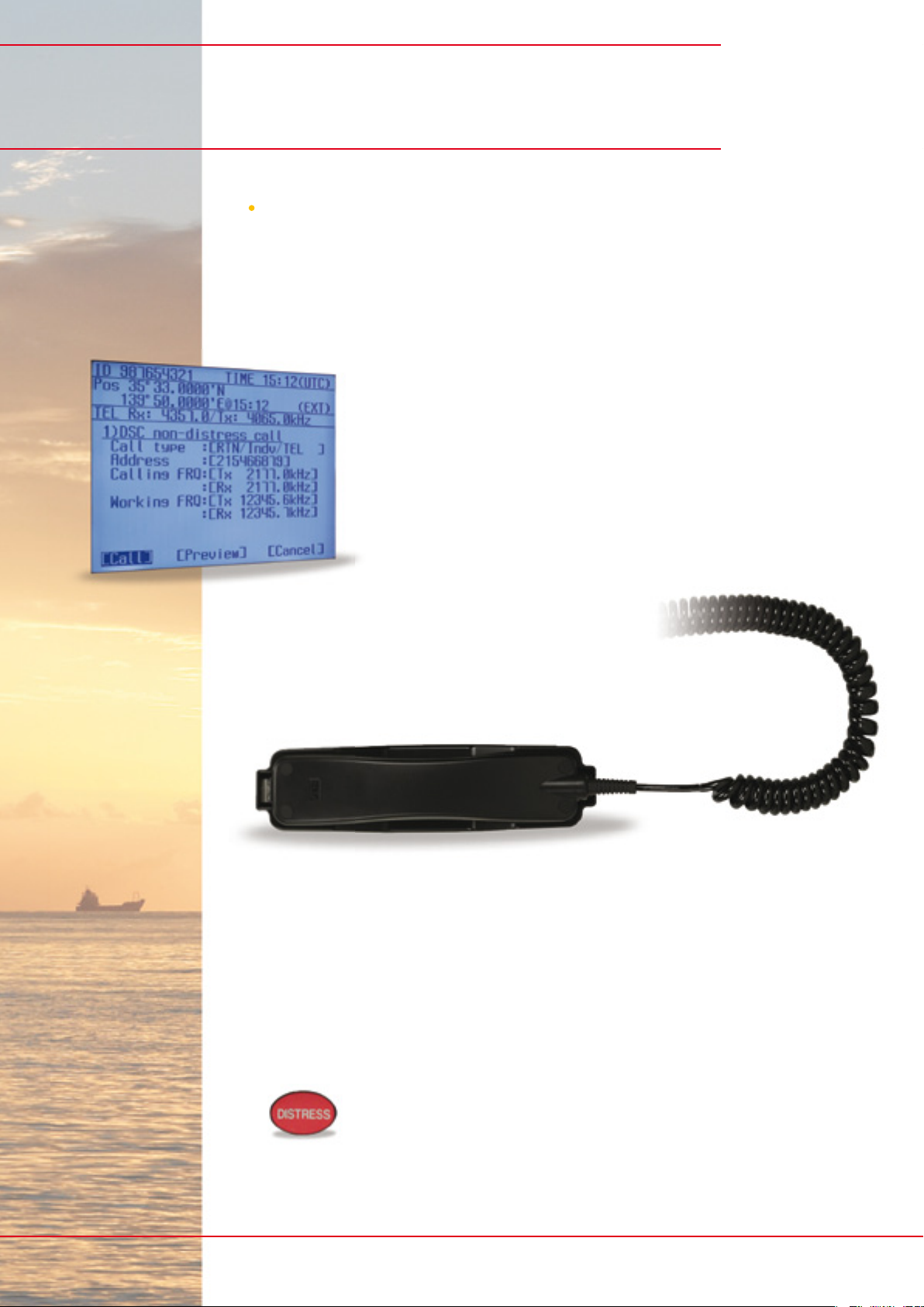
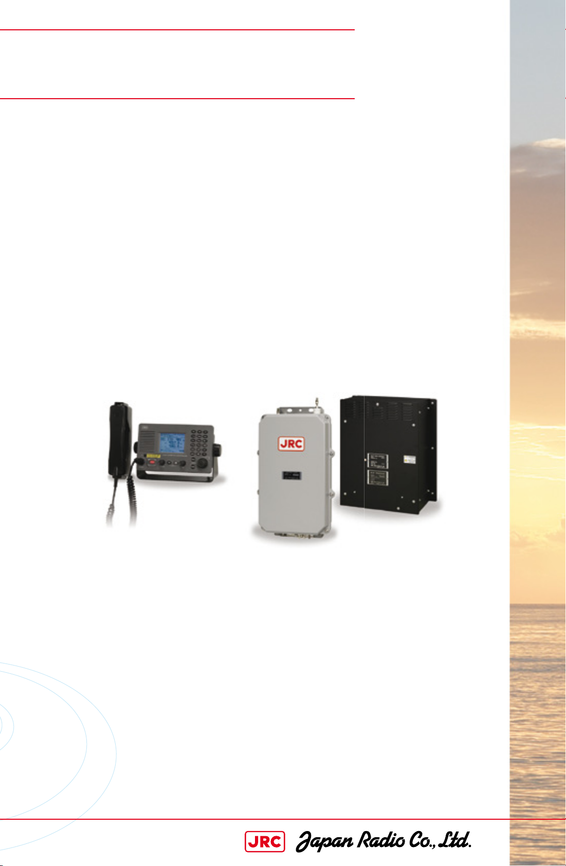
Model JSS-2150
IMO compliant
General
Display 3.8-inch, LED backlit, 320 by 240 pixels
Communication speed 57.6 kbps
Microphone input -54 dBm
Rated audio output speaker (8˜): °5W , handset (150˜): 1 mW or mor e
Frequency transmit 1605.0 to 27500.0 kHz (100 Hz steps)
Frequency receive 90.0 to 29999.9 kHz (100 Hz steps)
Emission type J3E, F1B, A1A, H3E, H2B, J2D
Channels up to 400 (20 ch x 20 groups)
ITU preset channels 831 ch
Channel switching time °15 sec
Communication method push-to-talk (simplex, semi-duplex)
Antenna impedance 50˜
Interface IEC61162-1 (GPS, RMS), NMEA0183
NMEA version 1.5, 2.0, 2.3
NMEA input GGA, GLL, RMC, GNS, ZDA
Power supply 21.6V to 31.2V DC
Power consumption 150W transmit: °30A, r eceive: °5A
Operating temperature -15° to 55°C (parts exposed to condensation -25° to 55°C)
Storage temperature -15° to 55°C (parts exposed to condensation -25° to 70°C)
Operating humidity 0% to 93% non-condensing
Protection rate IP22 (controller)
Transmitter
Antenna output power 1605.0 to 3999.9 kHz: 100Wpep
4000.0 to 27500.0 kHz: 150Wpep
Modulation method low-power stage balanced modulation
Occupied bandwidth J3E, J2D, H2B: within 3 kHz, F1B, A1A: within 0.5 kHz
Receiver
Receiving system double superheterodyne
Intermediate frequency 70.036 MHz, 36 kHz
Frequency stability within ±10 Hz
Sensitivity J3E: °2.5 uV , F1B: °0.7 uV , A1A: °1.4 uV
Clariÿ er variable range ±200 Hz (1 Hz steps)
Line output 0 dBm 600˜ (balanc ed)
Optional items
Power supply (AC/DC) NBD-2150
Battery charger NBB-724
Controller (max 2 in conÿ guration) NCM-2150
Mounting bracket for controller (˝ ush) MPBC42957
Mounting bracket for controller (table) MPBX44354
Connection box (for second controller) NQD-2250
Waterproof handset (IP66) NQW-261
Printer (wall, ˝ ush mount) NKG-91
Printer (desktop type) DPU-414, NKG-800
Junction box (for antenna tuner) NQD-2253
All speciÿ cations are subject to change without notiÿ cation.JRC has several antenna solutions available
© 2009.5 CAT.No.Y14-212 (No.814-1-3) A Printed in Japan