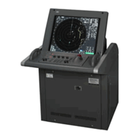
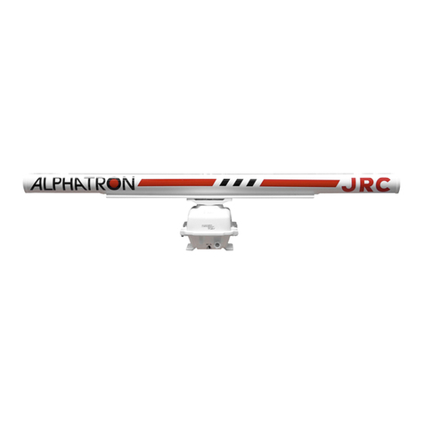
JRC JMA-933B User manual

Chart RADAR
Installation Manual


i
PREFACE
Thank you for purchasing the JRC JMA-900B Chart RADAR.
This manual describes how to install the equipment. For the best operation and
performance results, read this manual thoroughly before insallation.
For preventing electric shock and for securing periformance, grounding work is
needed.
Make sure to perform earth connection.
For the detailed operation, refer to the Instruction Manulal for JMA-900B.

ii
●Before Operation ●
Pictorial Indication
Various pictorial indications are included in this manual and are shown
on the component equipment so that you can operate them safely and
correctly and prevent any danger to you and / or to other persons and
any damage to your property during operation. Such indications and
their meanings are as follows.
Please understand them before you read this manual:
This indication is shown where any person is supposed to be in
danger of being killed or seriously injured if this indication is
neglected or equipment is not operated correctly.
This indication is shown where any person is supposed to be injured
or any property damage is supposed to occur if this indication is
neglected or equipment is not operated correctly.
Examples of pictorial indication
The △mark represents CAUTION (including DANGER and
WARNING).
Detailed contents of CAUTION (“Electric Shock” in the example on the
left) are shown in the mark.
The mark represents prohibition.
Detailed contents of the prohibited action (“Disassembling Prohibited”
in the example on the left) are shown in the mark.
The ●mark represents instruction.
Detailed contents of the instruction (“Disconnect the power plug” in the
example on the left) are shown in the mark.
Warning label
There is a warning label on the top cover of the equipment.
Do not try to remove, break or modify the label.

iii
●Precautions upon Equipment Operation ●
Before installing the power cable, make sure to turn off the braker of the main
power line. Otherwise, an electric shock or a malfunction may occur.
When connecting/disconnecting the connection cables between the external
equipment, make sure to turn off the braker of the main power line.
Otherwise, a fire or an electric shock may occur.

iv
Do not touch the LAN/USB connectors directly with your hands.
Otherwise, a malfunction may occur due to electrostatic charges.
Divert electrostatic charges by touching chassis before accessing LAN/USB
connectors.

CONTENTS
1. CONFIGURATION ...................................................................................................1-1
1.1 Components........................................................................................................................... 1-1
1.1.1 JMA-900B Series ............................................................................................................ 1-1
1.2 List of Circuits........................................................................................................................ 1-3
1.2.1 JMA-900B Series Scanner Unit, Tranceiver Unit.......................................................... 1-3
1.3 System Diagram..................................................................................................................... 1-8
1.4 System Configuration ......................................................................................................... 1-14
2. INSTALLATION OF SCANNER UNIT....................................................................2-18
2.1 Equipment Cable .................................................................................................................2-18
2.1.1 H-2695110056* .............................................................................................................. 2-18
2.1.2 H-2695111153* .............................................................................................................. 2-19
2.1.3 Cable end processing method .................................................................................... 2-20
2.1.4 Connection to Terminals ............................................................................................. 2-21
2.2 Installation of Scanner Unit ................................................................................................ 2-22
2.2.1 NKE-1125 Type Scanner .............................................................................................. 2-22
2.2.2 NKE-1129 Type Scanner .............................................................................................. 2-24
2.2.3 NKE-1130 Type Scanner .............................................................................................. 2-26
2.2.4 NKE-1139 Type Scanner .............................................................................................. 2-28
2.3 Installation of Tranceiver Unit............................................................................................. 2-30
2.3.1 NTG-3225 Type Tranceiver .......................................................................................... 2-30
2.3.2 NTG-3230 Type Tranceiver .......................................................................................... 2-32
2.4 Precautions .......................................................................................................................... 2-34
2.4.1 Insatallation of Scanner Unit ....................................................................................... 2-34
2.4.2 Routing Coaxial Cable and Flexible Waveguide ........................................................ 2-39
2.4.3 Scanner Installation Position ...................................................................................... 2-41
2.4.4 Confirmation during Test Run..................................................................................... 2-46
3. INSTALLATION OF DISPLAY UNIT ........................................................................3-1
3.1 Installation of Display Unit....................................................................................................3-1
3.2 Installing Power Cable........................................................................................................... 3-6
3.2.1 Input Voltage Specification............................................................................................ 3-6
3.2.2 Connecting Power Cable ............................................................................................... 3-6
3.3 Connections with Scanner and Transceiver........................................................................ 3-8
3.4 Connection with GPS ............................................................................................................ 3-9
3.5 Connection with Vessel Speed Unit (2-AXIS LOG)............................................................ 3-10
3.6 Connections with GYRO and Electormagnetic LOG......................................................... 3-11
3.7 Connection with GYRO (IEC61162-1/2) .............................................................................. 3-13
3.8 Connection with AIS ............................................................................................................ 3-15
3.9 Connection with ECDIS....................................................................................................... 3-16
3.10 Connect with Alarm Monitoring System ............................................................................ 3-17
3.11 Installation of Cable Ground............................................................................................... 3-18
4. INITIAL SETTING ....................................................................................................4-1
4.1 Confirming Power Supply ..................................................................................................... 4-1
4.2 Connecting to CQD-2121 Standard Terminal Board............................................................ 4-2
4.3 Setting Equipment Configuration......................................................................................... 4-4
4.3.1 Setting Ethernet Rotary Switch..................................................................................... 4-4
4.4 Connecting to CQD-2128 Radar Terminal Board................................................................. 4-6
4.5 Setting of GYRO I/F ............................................................................................................... 4-8
4.5.1 Setting of STEP・SYNC................................................................................................... 4-8
5. SETTING..................................................................................................................5-1
5.1 Port Setting ............................................................................................................................ 5-1
5.1.1 Display the Device Menu ............................................................................................... 5-1
5.1.2 Display the Configulation Set Menu ............................................................................. 5-2
5.1.3 The Configuration Setting ............................................................................................. 5-3

5.1.3.1 Select the equipment and the connect-acknowledge...................................... 5-3
5.1.3.2 Configuration Setting......................................................................................... 5-6
5.1.3.3 Sensor Setting.................................................................................................. 5-15
5.1.3.4 Alarm Relay Setting.......................................................................................... 5-22
5.1.3.5 Update of Application Software....................................................................... 5-26
5.1.3.6 Update of SRB/ROL Software .......................................................................... 5-31
5.1.4 Setting of the Sensor ................................................................................................... 5-34
5.2 Setting of the Ships Paramater........................................................................................... 5-37
5.3 Setting of the Installation Location .................................................................................... 5-38
5.4 Setting of the RADAR Application...................................................................................... 5-39
5.4.1 Setting of the Navigation Equipment.......................................................................... 5-40
5.4.2 Tune Adjustment .......................................................................................................... 5-41
5.4.3 Tune Indicator Adjustment .......................................................................................... 5-42
5.4.4 Bearing Adjustment ..................................................................................................... 5-43
5.4.5 Range Adjustment........................................................................................................ 5-44
5.4.6 Setting of the Antenna Height ..................................................................................... 5-45
5.4.7 Setting of the Main Bang Suppression....................................................................... 5-46
5.4.8 Adjustmant the Performance Monitor ........................................................................ 5-47
5.4.9 Setting of the equipment ID......................................................................................... 5-48
5.4.10 Setting of Alarm ........................................................................................................... 5-49
5.4.10.1 Setting of output cycle of watchman timer reset contact signal ................ 5-49
5.4.10.2 Setting of Alarm Volume ................................................................................ 5-49
5.4.10.3 Output Setting of Relay Contact Signal........................................................ 5-50
5.4.10.4 Output setting of ALR sentence.................................................................... 5-50
5.4.10.5 Setting of Outside ACK Receive.................................................................... 5-51
5.5 Backup of Data..................................................................................................................... 5-52
6. OPTION UNIT ..........................................................................................................6-1
6.1 Installation of Interswitch Unit.............................................................................................. 6-1
6.1.1 Equipment Cable End Processing ................................................................................ 6-1
6.1.2 Connection of Equipment Cable ................................................................................... 6-1
6.1.3 Plug Terminal Block Connecteion Procedures ............................................................ 6-2
6.1.4 Installation of Interswitch Unit ...................................................................................... 6-3
6.1.5 Setting............................................................................................................................. 6-7
6.1.6 Confirmation after Installation..................................................................................... 6-11
6.1.7 Inter-board Connection Diagram ................................................................................ 6-11
6.2 INSTALLATION of POWER CONTROL UNIT ...................................................................... 6-13
6.2.1 Connection with NKE-1125,NTG-3225,NKE-1130,NTG-3230 ..................................... 6-13
6.2.2 Equipment Cable End Processing .............................................................................. 6-14
6.2.3 End Processing of each cable core ............................................................................ 6-14
6.2.4 Connection to Display Unit ......................................................................................... 6-14
6.2.5 General System Diagram of Power Contorl Unit ....................................................... 6-15
6.2.6 Inter-board connection Diagram of Power Control Unit............................................ 6-27
6.2.7 Exterior Drawing of Power Control Unit..................................................................... 6-31
6.3 INSTALLATION of VDR ........................................................................................................ 6-33
6.3.1 Connetions ................................................................................................................... 6-33

1-1
1. Configuration
1.1 Components
A list of components and optional accessories are shown below.
1.1.1 JMA-900B Series
●JMA-900B Series List of Composition (Self Satanding TYPE)
MODEL Scanner
Unit Radiator Performance
Montor
Tranceiver
Unit Display Unit
JMA-933B-SA NKE-1139 NTG-3230
JMA-932B-SA NKE-1130
NJU-84
---
JMA-923B-7XA NKE-1129-7 NAX-16B-7
JMA-923B-9XA NKE-1129-9 NAX-16B-9
NTG-3225
JMA-922B-6XA NKE-1125-6 NAX-16B-6 ---
JMA-922B-9XA NKE-1125-9 NAX-16B-9
NJU-85
---
NCD-2096
●JMA-900B Series List of Composition (Desktop TYPE)
Display Unit NCD-2096F
MODEL Scanner
Unit Radiator
Perfor
mance
Monitor
Tranciver
Unit Monitor
Unit
Process
Unit
Operation
Unit
JMA-933B-SA NKE-1139 NTG-3230
JMA-932B-SA NKE-1130
NJU-84
---
JMA-923B-7XA NKE-1129-7 NAX-16B-7
JMA-923B-9XA NKE-1129-9 NAX-16B-9
NTG-3225
JMA-922B-6XA NKE-1125-6 NAX-16B-6 ---
JMA-922B-9XA NKE-1125-9 NAX-16B-9
NJU-85
---
NWZ-170-ET NDC-1444 NCE-5163-FT
*1 Input voltage is selectable. “1” or “2” suffix is attached to model name of scanner unit. “1” means
AC100-115V (50/60Hz) and “2” means AC220-240V (50/60Hz) for type of scanner unit NKE-1139,
NKE-1130, NKE-1129-7, NKE-1129-9, NKE-1125-6, NKE-1125-9.
*2 HETER OPTION is available at suffix “D”.
Ex)NKE-1139-1 D 、NKE-1129-92 D
1: AC 100-115V 50/60Hz 1φ
2: AC 220-240V 50/60Hz 1φ
D: HETER OPTION

1-2
●Accessories
NAME TYPE REMARKS
7ZPRD0694 (Japanese)
Radar Mode Instruction Manual
7ZPRD0695 (English)
7ZPRD0696 (Japanese)
ECDIS Mode Instruction Manual
7ZPRD0697 (English)
7ZPRD0744 (Japanese)
Simplified Manual
7ZPRD0745 (English)
7ZPNA4111 (Japanese)Additional Manual for
Chart Installation 7ZPNA4112 (English)
Accessory 7ZZNA0426A CD/FD Cleaner
Accessory 7ZZNA0427A FD(10 pieces)/FD Case
●Options
NAME TYPE REMARKS
7ZPRD0698 (Japanese)
Installation Maunal
7ZPRD0699 (English)
Hood MPOL30345A For LCD Monitor
Cover MPXP33088 For Display Unit
Mini Keyboard Kit MPXP33223A
Gyro Interface Kit MPXP34120 For Step Gyro and Puls
4unit Switching Interswitch NQE-3141-4A External
8unit Switching Interswitch NQE-3141-8A External (Custom Made)
Spare Parts 7ZSRD0025 For Gyro I/F Additional Kit

1-3
1.2 List of Circuits
1.2.1 JMA-900B Series Scanner Unit, Tranceiver Unit
Table 1-1 JMA-933B-SA Scanner and Tranceiver Unit
NKE-1139-1 NKE-1139-2
Scanner Unit
Interconnection CAX-14
Radiator CTG-270
Safety Switch CSD-657
Encoder CHT-71A1
Motor MDBW10823
AC100V Motor Driver 7EPRD0035* AC220V Motor Driver 7EPRD0034*
Brake Circuit CFA-255
Brake Control Circuit CCB-655
Brake Circuit Unit NZR-17
Heater Control Part
*DOption CHG-215
Scanner Unit
Performance Monitor NJU-84
NTG-3230
Transceiver Unit
Interconnection CMK-594
Modulator Unit NMA-553-1
Modulator Unit
Interconnection CMB-407
Modulator Circuit CPA-264
Receiver Unit NRG-229
Receiver Unit
Interconnection CMA-902
IF Circuit CAE-499
RF Circuit CAF-595
T/R Control Circuit CMC-1205R
Relay Filter Circuit CSC-656
Transceiver
Unit
Power Supply Circuit CBD-1682A
Display Unit NCD-2096/NCD-2096F
“*” means revision, such as A, B and so on.

1-4
Table 1-2 JMA-932B-SA Scanner Unit
NKE-1130-1 NKE-1130-2
Scanner Unit
Interconnection CAX-13
Radiator CTG-270
Safety Switch CSD-656
Encoder CHT-71A
Motor MDVW10823
AC100V Motor Driver 7EPRD0035* AC220V Motor Driver 7EPRD0034*
Brake Circuit CFA-255
Brake Contorl Circuit CCB-655
Brake Circuit Unit NZR-17
Modulator Unit NMA-551-1
Modulator Unit
Interconncetion CMB-406
Modulator Circuit CPA-264
Receiver Control Unit NZT-1130
Receiver Unit NRG-229
Receiver Unit
Interconnetion CMA-902
IF Circuit CAE-499
RF Circuit CAF-595
T/R Control Circuit CMC-1205R
Relay Fiter Circuit CSC-656
Powrer Supply Circuit CBD-1682A
Heter Control Part *DOption CHG-215
Scanner Unit
Performance Montor NJU-84
Display Unit NCD-2096/NCD-2096F
“*” means revision, such as A, B and so on.

1-5
Tabel 1-3 JMA-923B-7XA/JMA-923B-9XA Scanner and Tranceiver Unit
NKE-1129-1 NKE-1129-2
Scanner Unit
interconnection CAX-12
Safety Switch CSD-655
Encoder CHT-71A1
Motor MDBW10822
AC100V Motor Driver 7EPRD0035* AC220V Motor Driver 7EPRD0034*
Brake Circuit CFA-253
Brake Control Circuit CCB-655
Brake Circuit Unit NZR-15
Heater Control Part
*DOption CHG-216
Scanner Unit
Perforimance Montor NJU-85
NTG-3225
Transceiver Unit
Interconnection CMK-593
Modulator Unit NMA-552-1
Modulator Unit
Interconnection CMB-405
Modulator Circuit CPA-264
MAG Filter Circuit CFR-229
Receiver unit NRG-162A
Receiver Circuit CMA-866A
T/R Control Circuit CMC-1205R
Relay Filter Circuit CSC-656
Tranciver Unit
Power Supply Circuit CBD-1682A
Display Unit NCD-2096/NCD-2096F
“*” means revision, such as A, B and so on.

1-6
Table 1-4 JMA-922B-6XA/JMA-922B-9XA Scanner Unit
NKE-1125-61,NKE-1125-91 NKE-1125-62,NKE-1125-92
Scanner Unit
Interconnection CAX-11
Safety Switch CSD-654
Encoder CHT-71A
Motor MDBW10822
AC100V Motor Driver 7EPRD0035* AC220V Motor Driver 7EPRD0034*
Brake Circuit CFA-253
Brake Control Circuit CCB-655
Brake Circuit Unit NZR-16
Modulator Unit NMA-550-1
Modulator Unit
Interconnection CMB-404
Modulator Circuit CPA-264
MAG Filter Circuit CFR-229
Receiver Unit NRG-162A
Receiver Circuit CMA-866A
T/R Control Circuit CMC-1205R
Relayfilter Circuit CSC-656
Power Suppley Circuit CBD-1682A
Heater Control Part
*DOption CHG-216
Scanner Unit
Performance Monitor NJU-85
Display Unit NCD-2096/NCD-2096F
“*” means revision, such as A, B and so on.

1-7
Table 1-5 NCD-2096/NCD-2096F Display Unit
NCD-2096 NCD-2096F
NDC-1445 NDC-1444
μATX Mother Board CMC-1323
ADD Card CKA-141
Flash Disk CDD-723
HDD (2 units) CDD-717
USB FD Drive CDD-719
DVD Drive CDD-719
ATX Power Supply CBD-1625
Front Panel Circuit 1 CCK-986
Front Panel Circuit 2 CCK-987
USB Secilty Dongle CYC-344
JMA-900B Display Unit
Software CYC-436
e-Token CYC-242
SRB CDJ-2373
Backplane Mother Board CQD-1219
Standard Terminal Circuit CQD-2121
Main Power Supply CBD-1832
UPS Battery CBD-1531
Radar I/F Board CDC-1338
Radar Processer Board CDC-1339
ARPA Process CDC-1186D
Radar Terminal Circuit CQD-2128
Control Unit Interconnection CFQ-5437
Process Unit
Process Unit Interconnection CFQ-5438
NCE-5163-F NCE-5163-FT
Operation Circuit A CCK-973
Operation Circuit B CCK-974
Operation Circuit C CCK-975
Operation Circuit D CCK-976
Operation Unit
Operation Unit
Interconnection CMD-996-F
Opeation Unit
Interconnection CMD-996-FT
NWZ-170-E NWZ-170-ET
LCD Pannel 7WSRD0002*
LCD Operation Circuit CCK-972
Monitor Unit
Monitor Unit Interconnection CML-764-E
Monitor Unit
Interconnection CML-764-ET
“*” means revision, such as A, B and so on.

1-8
1.3 System Diagram
NCD-2096
DISPLAY UNIT
NJU-84
PERFORMANCE
MONITOR
250V-MPYCYS-7
250V-TTYCS-1
KB-CHD152K
250V-TTYCS-1
18 CORES COMPOSITE CABLE
H-2695111153
MAX 18.0φ(JRC SUPPLY)
250V-TTYCS-4
H-2695110006 (JRC SUPPLY)
H-2668510019 (JRC SUPPLY) SPARE
250V-MPYC-4
250V-TTYCS-4
250V-TTYCS-4
GYRO
LOG(NMEA 0183)
DGPS
VDR
RADAR(INTER SWITCH)
ECDIS(JAN-901M)
ALERM MONITORING SYSTEM
(NEAREST APPROACH)
(POWER FAIL)
CONNING DISPLAY(JAN-701-CON)
AIS
0.6/1kV-DPYCY-6
0.6/1kV-DPYCYS-1.5
SHIP’S MAIN
AC100/220V,
50/60Hz,1φ,800VA
SHIP’S MAIN
for POWER FAIL ALARM
DC24V(BATTERY),1W
(5A)
NBL-175 SHIP’S MAIN
for HEATER
AC220V,50/60Hz,1φ
AC100V,50/60Hz
1φ,200W
CIRCUIT BREAKER
(SHIP YARD SUPPLY)
(WITH MON)
NKE-1139-1/2
SCANNER UNIT
14 CORES COMPOSITE CABLE
H-2695110056
MAX 23φ(JRC SUPPLY) 35m MAX
STEPDOWN
TRANSFORMER
NTG-3230
TRANSCEIVER-RECEIVER UNIT
14 CORES COMPOSITE CABLE
H-2695110056
MAX 23φ(JRC SUPPLY) 30m MAX
COAXIAL CABLE
HF-20D (JRC SUPPLY)
0.6/1kV-DPYCYS-1.5
HEATER OPTION
Fig 1-1 JMA-933B-SA System Diagram

1-9
NCD-2096
DISPLAY UNIT
NJU-84
PERFORMANCE
MONITOR
250V-MPYCYS-7
250V-TTYCS-1
KB-CHD152K
250V-TTYCS-1
18 CORES COMPOSITE CABLE
H-2695111153
MAX 18.0φ(JRC SUPPLY)
250V-TTYCS-4
H-2695110006 (JRC SUPPLY)
H-2668510019 (JRC SUPPLY) SPARE
250V-MPYC-4
250V-TTYCS-4
250V-TTYCS-4
GYRO
LOG(NMEA 0183)
DGPS
VDR
RADAR(INTER SWITCH)
ECDIS(JAN-901M)
ALERM MONITORING SYSTEM
(NEAREST APPROACH)
(POWER FAIL)
CONNING DISPLAY(JAN-701-CON)
AIS
0.6/1kV-DPYCY-6
0.6/1kV-DPYCYS-1.5
SHIP’S MAIN
AC100/220V,
50/60Hz,1φ,800VA
SHIP’S MAIN
for POWER FAIL ALARM
DC24V(BATTERY),1W
(5A)
NBL-175 SHIP’S MAIN
for HEATER
AC220V,50/60Hz,1φ
AC100V,50/60Hz
1φ,200W
CIRCUIT BREAKER
(SHIP YARD SUPPLY)
(WITH MON)
NKE-1130-1/2
SCANNER UNIT
14 CORES COMPOSITE CABLE
H-2695110056
MAX 23φ(JRC SUPPLY) 65m MAX
STEPDOWN
TRANSFORMER
0.6/1kV-DPYCYS-1.5
HEATER OPTION
Fig 1-2 JMA-932B-SA System Diagram

1-10
NCD-2096
DISPLAY UNIT
NJU-85
PERFORMANCE
MONITOR
250V-MPYCYS-7
250V-TTYCS-1
KB-CHD152K
250V-TTYCS-1
18 CORES COMPOSITE CABLE
H-2695111153
MAX 18.0φ(JRC SUPPLY)
250V-TTYCS-4
H-2695110006 (JRC SUPPLY)
H-2668510019 (JRC SUPPLY) SPARE
250V-MPYC-4
250V-TTYCS-4
250V-TTYCS-4
GYRO
LOG(NMEA 0183)
DGPS
VDR
RADAR(INTER SWITCH)
ECDIS(JAN-901M)
ALERM MONITORING SYSTEM
(NEAREST APPROACH)
(POWER FAIL)
CONNING DISPLAY(JAN-701-CON)
AIS
0.6/1kV-DPYCY-6
0.6/1kV-DPYCYS-1.5
SHIP’S MAIN
AC100/220V,
50/60Hz,1φ,800VA
SHIP’S MAIN
for POWER FAIL ALARM
DC24V(BATTERY),1W
(5A)
NBL-175 SHIP’S MAIN
for HEATER
AC220V,50/60Hz,1φ
AC100V,50/60Hz
1φ,100W
CIRCUIT BREAKER
(SHIP YARD SUPPLY)
(WITH MON)
NKE-1129-71/72
SCANNER UNIT
14 CORES COMPOSITE CABLE
H-2695110056
MAX 23φ(JRC SUPPLY) 35m MAX
STEPDOWN
TRANSFORMER
NTG-3225
TRANSCEIVER-RECEIVER UNIT
14 CORES COMPOSITE CABLE
H-2695110056
MAX 23φ(JRC SUPPLY) 30m MAX
FLEXIBLE WAVEGUIDE
FR-9 (JRC SUPPLY)
0.6/1kV-DPYCYS-1.5
HEATER OPTION
Fig 1-3 JMA-923B-7XA System Diagram

1-11
NCD-2096
DISPLAY UNIT
NJU-85
PERFORMANCE
MONITOR
250V-MPYCYS-7
250V-TTYCS-1
KB-CHD152K
250V-TTYCS-1
18 CORES COMPOSITE CABLE
H-2695111153
MAX 18.0φ(JRC SUPPLY)
250V-TTYCS-4
H-2695110006 (JRC SUPPLY)
H-2668510019 (JRC SUPPLY) SPARE
250V-MPYC-4
250V-TTYCS-4
250V-TTYCS-4
GYRO
LOG(NMEA 0183)
DGPS
VDR
RADAR(INTER SWITCH)
ECDIS(JAN-901M)
ALERM MONITORING SYSTEM
(NEAREST APPROACH)
(POWER FAIL)
CONNING DISPLAY(JAN-701-CON)
AIS
0.6/1kV-DPYCY-6
0.6/1kV-DPYCYS-1.5
(5A)
NBL-175 SHIP’S MAIN
for HEATER
AC220V,50/60Hz,1φ
AC100V,50/60Hz
1φ,100W
CIRCUIT BREAKER
(SHIP YARD SUPPLY)
(WITH MON)
NKE-1129-91/92
SCANNER UNIT
14 CORES COMPOSITE CABLE
H-2695110056
MAX 23φ(JRC SUPPLY) 35m MAX
STEPDOWN
TRANSFORMER
NTG-3225
TRANSCEIVER-RECEIVER UNIT
14 CORES COMPOSITE CABLE
H-2695110056
MAX 23φ(JRC SUPPLY) 30m MAX
FLEXIBLE WAVEGUIDE
FR-9 (JRC SUPPLY)
0.6/1kV-DPYCYS-1.5
SHIP’S MAIN
AC100/220V,
50/60Hz,1φ,800VA
SHIP’S MAIN
for POWER FAIL ALARM
DC24V(BATTERY),1W
HEATER OPTION
Fig 1-4 JMA-923B-9XA System Diagram

1-12
NCD-2096
DISPLAY UNIT
NJU-85
PERFORMANCE
MONITOR
250V-MPYCYS-7
250V-TTYCS-1
KB-CHD152K
250V-TTYCS-1
18 CORES COMPOSITE CABLE
H-2695111153
MAX 18.0φ(JRC SUPPLY)
250V-TTYCS-4
H-2695110006 (JRC SUPPLY)
H-2668510019 (JRC SUPPLY) SPARE
250V-MPYC-4
250V-TTYCS-4
250V-TTYCS-4
GYRO
LOG(NMEA 0183)
DGPS
VDR
RADAR(INTER SWITCH)
ECDIS(JAN-901M)
ALERM MONITORING SYSTEM
(NEAREST APPROACH)
(POWER FAIL)
CONNING DISPLAY(JAN-701-CON)
AIS
0.6/1kV-DPYCY-6
0.6/1kV-DPYCYS-1.5
SHIP’S MAIN
AC100/220V,
50/60Hz,1φ,800VA
SHIP’S MAIN
for POWER FAIL ALARM
DC24V(BATTERY),1W
(5A)
NBL-175 SHIP’S MAIN
for HEATER
AC220V,50/60Hz,1φ
AC100V,50/60Hz
1φ,100W
CIRCUIT BREAKER
(SHIP YARD SUPPLY)
(WITH MON)
NKE-1125-61/62
SCANNER UNIT
14 CORES COMPOSITE CABLE
H-2695110056
MAX 23φ(JRC SUPPLY) 65m MAX
STEPDOWN
TRANSFORMER
0.6/1kV-DPYCYS-1.5
HEATER OPTION
Fig 1-5 JMA-922B-6XA System Diagram
This manual suits for next models
5
Table of contents
Other JRC Radar manuals
Popular Radar manuals by other brands

icoms
icoms TMA 3B3 user guide

Radenso
Radenso Pro M installation guide

Honeywell
Honeywell SMARTLINE RM77 Supplementary instructions

Endress+Hauser
Endress+Hauser Micropilot M FMR244 operating instructions

Carmanah
Carmanah SpeedCheck-15 install guide

Decatur Electronics
Decatur Electronics Genesis VP Directional user manual

Endress+Hauser
Endress+Hauser Levelflex FMP56 Brief operating instructions

Carmanah
Carmanah MX Series install guide

Hesai
Hesai Pandar 128E3X user manual

Motorline professional
Motorline professional MR30 User's and installer's manual

CognitiveTPG
CognitiveTPG CPRR user manual

Honeywell
Honeywell SmartLine SLG 700 user manual