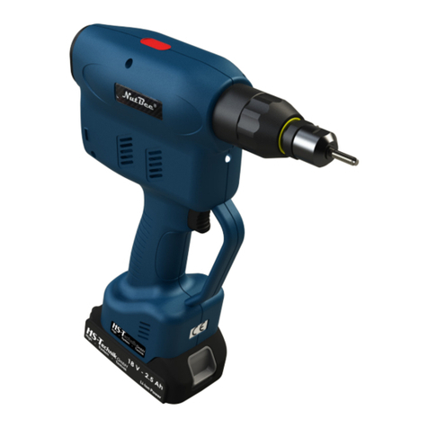
JRP NB80A User manual

QUALITY •SERVICE • PERFORMANCE
R
NB80A
Battery Blind Rivet Nut Tool
Installation Manual
www.jrprivets.co.uk

2
Contents Page
SAFETY INSTRUCTIONS/WARNINGS 3
TOOL MAINTENANCE AND
ENVIRONMENTAL COMPLIANCE 4
TOOL OVERVIEW
Key Parts 4
Technical Dimensions and Capacity 5
Wearing Parts and Accessories 6
Wearing Parts List 6
Full Parts List and Exploded Drawing 7-8
PREPARATION BEFORE USE
Changing the Mandrels 9
Setting the Mandrel/Head and Adjustment Nut 10
Checking the Battery 11
Checking the Tool 11
FUNCTION SETTINGS
Setting the Traction Force 12
Unlocking the Function Settings 12
Setting the Stroke Adjustment 13
Riveting in Conventional Mode 14
Riveting in Fully Automatic Mode 14
TOOL OPERATION
Checks and Pre-Installation 15
Checking the Rivet Nut Setting 15
Manually Unscrewing Rivet Nuts 16
Rivet Nut Setting Process 16
CHARGER AND BATTERIES
Charger Technical Capabilities 17
Battery Technical Capabilities 17
FAQ (QUESTIONS/ANSWERS) 18
TROUBLESHOOTING
Malfunctions 19
Probable Causes 19
Corrective Action 19
CE/UKCA CERTIFICATION AND WARRANTY 20

3
SAFETY INSTRUCTIONS/WARNINGS
To reduce the risk of personal injury to yourself and/or others, or property damage, please be sure to follow the safety
instructions below.
Description of the warnings:
Danger - A cause of potential danger of serious injury/death.
Warning - A cause of potential danger of serious injury/death.
Caution - A cause of risk of minor injury or loss of property.
Description of actions to be followed:
This is to alert the user to prohibited actions.
This is to advise the operating steps that must be followed to correctly use the appliance.
This tool is restricted to setting blind rivet nuts and must not be used for any other purpose, especially any impact use.
Only use the tool within the specied setting ranges in the function settings. Oversetting can cause severe damage.
(See pages 15-17).
Do not block or insert objects into the motor ventilation on the tool body.
It is recommended that you wear safety glasses, any personal protective equipment and adhere to all relevant safe
practice measures when using this tool.
Please handle with care all of the accessories within the plastic case. The tool and accessories should be kept in
the plastic case, stored in a dry place and out of reach of children.
Battery Use
• Please ensure that the battery is charged to 100% on rst use. Approximate charging time is about an hour.
• Do not charge damaged, leaking, or wet batteries.
• Batteries must not be put in re or water at any point.
• Used batteries must be disposed of safely and in compliance with respective governing country regulations.
• Do not charge when the ambient temperature is below 0°C or above 45°C.
Charger Use
• Only the original manufacturer’s charger must be used for charging the battery.
• The battery must be charged with a clean, dry, and undamaged charger.
• Ensure there are no metal objects in the charging area to create a possible short circuit.
• This charger must not be used by any person without prior training unless a safety ofcer is on-site to supervise or
instruct them.
Danger
• Do not use near ammable liquids/gases that can cause a risk of explosion.
• Do not use the tool in a damp environment that can cause the risk of electric shock.
• Do not operate the tool aimed at yourself/others.
Warning
• Tools should be placed down safely to prevent any falls that can cause unnecessary damage.
• When installing the battery and after hearing a “click” sound, ensure that the battery is rmly locked in place.
• Before charging, check that the charger and its power supply equipment are in good condition.
• Use a power supply unit that matches the charger.
• Plugs, power leads and chargers should be checked regularly to comply with all safe practice procedures.
• Maintenance personnel must be qualied professionals to carry out any repairs. If in doubt, please return the tool to
the authorised distributor for repair.
• When servicing the tool, always ensure the battery is removed.
• Only original spare parts must be used during maintenance.


4
TOOL MAINTENANCE AND ENVIRONMENTAL COMPLIANCE
Maintenance
• Regular maintenance prolongs the life of tools with a lithium battery and should be carried out by qualied maintenance
personnel or an authorised repair agent.
• To keep the tool in a good working condition, please check common wearing parts (mandrels, heads etc) on a regular
basis.
• In case of damage or possible warranty claim, please contact your authorised distributor.
Repair
• The 12-month return to base warranty for this tool is from the date of purchase. All wearing parts e.g., mandrels, heads,
etc. are excluded with the exception of a manufacturing fault/faults.
• All repairs should only be carried out by qualied maintenance personnel or an authorised repair agent. If in doubt,
please return the tool to your authorised distributor for repair.
Environmental Compliance
When replacing the lithium batteries used in this product, be sure to observe that all used batteries must be disposed of
safely and in compliance with respective governing country regulations.
Failure to comply with all/any of the warnings and instructions will invalidate the manufacturer’s warranty.
1. Head
2. Mandrel
3. Adjustment Nut
4. Control Panel
5. Battery
6. Rear Cover
7. Body
8. Illuminating Light
9. Trigger
10. Charger
Key Parts
TOOL OVERVIEW
Deutsch | 2Deutsch | 4
www.goebel-group.com
1. Tool overview
1
2
3
4
5
6
7
8
9
10
Component
Maintenance
•Regular maintenance prolongs the life of tools with a lithium battery and should be
carried out by an authorised dealer or manufacturer. In case of more frequent use, it
is recommended to carry out maintenance in advance.
•Maintenance of the riveting tool is limited only to replacement of worn parts and
quick wear parts, jaws, jaw sliders, etc., if necessary (see P8 for replacement acces-
sories).
•To keep the tools in good working condition, please check the wear parts of the tools
frequently. In case of wear or damage, please contact the dealer for purchase.
Repair
•The warranty period is 1 year from the date of sale. Excluded from this are quick wear
parts e.g. clamping jaws, clamping jaw sliders etc.
•Failure to comply with the relevant installation and commissioning instructions or fai-
lure to follow the operating procedures may result in the warranty being invalidated.
Environmental protection and resource recovery
•When replacing lithium batteries used in this product, be sure to observe the following
points:
•If your country or region has regulations, please be sure to take the old battery to a
professional company for disposal.
•Do not throw old batteries into the rubbish, re or water!
1
2
3
4
5
6
7
8
9
10
Threaded sleeve
Mandrel
Steel sleeve
Function display
Battery
Back cover
Tool housing
LED lighting
Trigger
Charger
Capacity Guide
Thread Size Rivet Nut Material
Alum Steel A2 St/St A4 St/St
M3
M4
M5
M6
M8
M10 X X X X
M12 X X X X
NB80A

5
Tool comes complete with M3, M4, M5, M6 and M8 mandrels and heads.
Technical Dimensions and Capacity
Technical Data
Capacity M3-M8
Material Capabilities All round body, semi and full hexagonal
blind rivet nuts in all materials.
Motor Type 18V Brushless Technology
Vibration Magnitude 1.5m/s2
Noise Level < 90dB
Riveting Style Conventional Spin/Pull & Fully Automatic
Traction Force 18000N
Stroke Length (adjustable) 6.0mm Max
Capacity Guide
Thread Size Rivet Nut Material
Alum Steel A2 St/St A4 St/St
M3
M4
M5
M6
M8
M10 X X X X
M12 X X X X
2| Deutsch5| English
www.goebel-group.com
1.1 Capacity / Technical parameters
260
21.5
21.5
21.5
GO-RN1
270
45
92
64
93,5
21,5
Model GO-RN1 GO-RN2 GO-SN1
Motor 18V Brushless motor
Noise level < 78dB
Riveting mode Conventional riveting mode / Fully automatic riveting mode
Traction force 18000N 27000N 21000N
Stroke 6 mm (adjustable) 9 mm (adjustable) 15,6 mm (adjustable)
Net weight (incl. battery) 1,5Kg 1,64Kg 1,64Kg
Capacity M3 - M8 M5 - M12 M5 - M10
Material specication All materials and specications of round shank, semi
and full hexagonal blind rivet nuts.
Split blind rivet nuts -
all materials
1.2 Conguration / Accessories
(Fig. A)
302
92
64
125
23,5
45
GO-SN1
2| Deutsch5| English
www.goebel-group.com
1.1 Capacity / Technical parameters
260
21.5 21.5 21.5
GO-RN1
270
45
92
64
93,5
21,5
Model GO-RN1 GO-RN2 GO-SN1
Motor 18V Brushless motor
Noise level < 78dB
Riveting mode Conventional riveting mode / Fully automatic riveting mode
Traction force 18000N 27000N 21000N
Stroke 6 mm (adjustable) 9 mm (adjustable) 15,6 mm (adjustable)
Net weight (incl. battery) 1,5Kg 1,64Kg 1,64Kg
Capacity M3 - M8 M5 - M12 M5 - M10
Material specication All materials and specications of round shank, semi
and full hexagonal blind rivet nuts.
Split blind rivet nuts -
all materials
1.2 Conguration / Accessories
(Fig. A)
302
92
64
125
23,5
45
GO-SN1
282
23.5
102
20
92
64
45
55
260
68
37

6
No Article Number Description Qty/Tool
1 TSBL43249H00 M6 Head 1
2 TSBL43232H00 Adjustment Nut 1
3 TSBL43243H00 M6 Mandrel 1
4 TSBL43252H00 M3 Head 1
5 TSBL43251H00 M4 Head 1
6 TSBL43250H00 M5 Head 1
7 TSBL43248H00 M8 Head 1
10 TSBL43246H00 M3 Mandrel 1
11 TSBL43245H00 M4 Mandrel 1
12 TSBL43244H00 M5 Mandrel 1
13 TSBL43242H00 M8 Mandrel 1
16 TSBZ41718H00 Battery 18V 2Ah 36W 2
17 TSBZ41734H00 Charger UK ECP-BR-5A 1
18 TSBF60273H00 Hex Key 1
19 TSBL42157H00 Spanner 1
20 TSBB01642H00 Storage Case (*) 1
Please Note:-
(*) Factory order part on request.
Wearing Parts and Accessories
Wearing Parts List
5
Name of part
①Anvil ②Mandrel
③Counter nut ④Display panel
⑤Battery ⑥Rear cover
⑦Body ⑧Illuminating light
⑨Trigger ⑩Charger
Outline Dimension(mm) See fig.
NB80WA-NB120A NB100LA Interchangable parts——NB80WA-NB120A-NB100LA
No. Name
Code
Spec Qty. No. Name
Code
Spec Qty.
18 Battery Z41718H00
18V-2.0A-36Wh
221 Wrench L41244H00 1
19 Charger Z41719H00 18V-2.0A 122 Plastic box B01642H00 1
20 Hex-key F60273H00 1
NB80WA;NB120A——Configuration
No. Name
Code
Spec Qty. No. Name
Code
Spec Qty.
1Anvil L43249H00 M6 1 9 Anvil L43231H00
M12 1
2Counter nut L43232H00 110 L43246H00 M3 1
3 Mandrel L43243H00 M6 111 L43245H00 M4 1
· Parameters 4L43252H00 M3 112 L43244H00 M5 1
Drive:
18V Brushl
Mode setting Normal/Auto Noise: <90dB 5L43251H00 M4 113 L43242H00 M8 1
6Anvil L43250H00 M5 114 L43241H00 M10 1
Type Power Stroke Range
N.w.(incl.
battery)
7L43248H00 M8 115 L43230H00 M12 1
NB80WA 18000N
6mm(adjustable)
M3-M8
1.5Kg 8L43247H00 M10 1
NB120A 24000N
mm(adjustable)
M3-M12
1.64Kg
NB100LA 18000N
.6mm(adjustable
M3-M10 1.6Kg NB100L —— Confiuration
· Packing info No. Name
Code
Spec Qty. No. Name
Code
Spec Qty.
1Anvil L43249H00 M6 1 8 Anvil L43247H00 M10 1
tool in
box
1
ox dimension(cm
38.5*28.5*7.6 2Counter nut L43232H00 113a L43151H00 M5 1
box in
carton
7
ton dimension(c
58.5*39.5*32 3a Mandrel L43152H00 M6 114a Mandrel L43153H00 M8 1
6L43250H00 M5 115a L43154H00 M10 1
Type NB80WA NB120A NB100LA 7L43248H00 M8 1
Box 3.4Kg 3.54Kg 3.5Kg
1· Tool overvi
· Configuration/Accessories
All material, round, simi-
hex,Hex nut
Anvil
alu, steel, hollow nut
Capcity
*NB80WA;M3 is optional part;NB120A;M3~M4 are op
Mandrel
FigA
· Standard se

7
No Article Number Description Qty/Tool
1 TSBL43249H00 M6 Head 1
2 TSBL43232H00 Adjustment Nut 1
3 TSBL43243H00 M6 Mandrel 1
4 TSBL43252H00 M3 Head 1
5 TSBL43251H00 M4 Head 1
6 TSBL43250H00 M5 Head 1
7 TSBL43248H00 M8 Head 1
10 TSBL43246H00 M3 Mandrel 1
11 TSBL43245H00 M4 Mandrel 1
12 TSBL43244H00 M5 Mandrel 1
13 TSBL43242H00 M8 Mandrel 1
16 TSBZ41718H00 Battery 18V 2Ah 36W 2
17 TSBZ41734H00 Charger UK ECP-BR-5A 1
18 TSBF60273H00 Hex Key 1
19 TSBL42157H00 Spanner 1
20 TSBB01642H00 Storage Case (*) 1
Full Parts List and Exploded Drawing
Turnover for full list
2| Deutsch7| English
www.goebel-group.com
Abb. B
1.3 Part list (Fig. B)
5

8
No Article Number Spec. Qty/Tool Description
1 TSBL43249H00 M6 1 M6 Head
2 TSBL43232H00 1 Adjustment Nut
3 TSBL43243H00 M6 1 M6 Mandrel
4 TSBL23002H00 1 Screw Cover
5 TSBZ42050H00 1 Nosepiece Pedestal
6 TSBZ42078H00 1 Cover Tube
7 TSBZ41819H00 1 Gear Box
8 TSBZ41922H00 1 Brushless Motor
9 TSBZ41806H00 1 Gears Assembly
10 TSBF60577H00 9 Self-Drill Screw
11 TSBZ41709H00 1 Body (Blue)
12 TSBL42296H00 1 Rear Cover
13 TSBZ41876H00 1 PCB
14 TSBL42162H00 1 Spring for Trigger
15 TSBL42133H00 1 Trigger
16 TSBL42239H00 1 Control Panel
17 TSBL43252H00 M3 1 M3 Head
18 TSBL43251H00 M4 1 M4 Head
19 TSBL43250H00 M5 1 M5 Head
20 TSBL43248H00 M8 1 M8 Head
24 TSBL43246H00 M3 1 M3 Mandrel
25 TSBL43245H00 M4 1 M4 Mandrel
26 TSBL43244H00 M5 1 M5 Mandrel
27 TSBL43242H00 M8 1 M8 Mandrel
31 TSBZ41718H00 18V-2.0A-36Wh 2 Battery
32 TSBZ41734H00 18V-2.0A 1 Charger, UK ECP-BR-5A
33 TSBF60273H00 1 Hex Key
34 TSBL42157H00 1 Spanner
Primary Spares Secondary Spares Warranty Parts
Full Parts List

9
PREPARATION BEFORE USE
Danger - Please read the instructions carefully before use.
Changing the Mandrels
Ensure the battery is removed from the riveting tool before carrying out any work to prevent any risk of injury.
Select the appropriate mandrel and head for the thread size of the blind rivet nut you require.
The procedure for removing the mandrel is as follows:-
1. Make sure that the battery has been removed from the tool.
2. Loosen the adjustment nut with the spanner.
3. Unscrew the head and adjustment nut completely.
4. Guide the round hole of the spanner over the threaded mandrel.
5. Push the spanner back against the spring-loaded sleeve to release the mandrel.
6. Unscrew the threaded mandrel and remove.
The procedure for inserting the new mandrel is as follows:-
1. Select the new mandrel size you require.
2. Guide the round hole of the spanner over the threaded mandrel and push back the spring-loaded sleeve to
thread the mandrel into the sleeve.
3. Screw the mandrel all the way in until the hexagon part can’t be seen, then release the pressure. Rotate
mandrel to ensure it has locked in place.
4. Replace the adjustment nut onto the corresponding head for the new mandrel size and screw into place.
5. Tighten the adjustment nut before use.
6. Connect battery, ready for use.
2| Deutsch9| English
www.goebel-group.com
2. Preparation of the tool
Danger - 2.1 Exchange of the mandrels
Make sure that you remove the battery from the riveting tool before replacing the mandrel
and nosepiece, otherwise there is a risk of injury! Select the appropriate mandrel with
corresponding nosepiece that match the size of the blind rivet nut. The procedure for
replacing the components is shown in the following illustration:
Before operating the riveting tool, please read the following important instructions carefully.
Make sure that the battery has been removed from the tool as shown in gure ① In the or-
der shown above: ② loosen the lock nut with the wrench, ③ unscrew the threaded sleeve
and guide the round hole of the spanner onto the threaded mandrel, ⑤ use the spanner to
push down the sleeves in the direction of the arrow ⑥ then unscrew the threaded mandrel.
In the sequence shown above, ① the round hole of the wrench is aligned with the mandrel,
②the sleeve is pressed down with the wrench in the direction of the arrow, held, the
mandrel is screwed in ③ the mandrel is screwed in in a clockwise direction until the
hexagonal part of the mandrel is no longer visible in the sleeve (engaged is after a 60
degree turn, the mandrel is correctly installed ④ The nosepiece is screwed on ⑤ and the
counter nut is tightened with the wrench ⑥ The battery is inserted into the tool last.

10
Setting the Mandrel/Head and Adjustment Nut
The setting of the mandrel/head and adjustment nut correctly is all according to the length of the blind rivet nut to be
used.
The setting up is as follows:
Deutsch | 2English | 10
www.goebel-group.com
2.3 Checking the battery
➁Battery status indicator light ➀Button
Press button ➀ once to check the battery.
The battery status indicator light ➁ is always green:
•Full indicator, 100% energy
•Three lights, 75% energy
•Two lights, 50% energy
•One light, 25% energy. Please charge!
2.2 Adjustment of the mandrel
Adjust the length of the mandrel correctly according to the length of the blind rivet nut
(see g.) The order of adjustment is as follows:
According to the above illustration: ① Sscrew the blind rivet nut onto the mandrel ②
loosen the counter nut, adjust according to ③ and ④ as the gure ⑤ shows, check that
the mandrel protrudes ≈ 1.5 mm above the blind rivet nut after adjustment - the mandrel is
correctly adjusted ⑥ tighten the counter nut with the wrench in the direction of the arrow.
1. Partially screw the rivet nut onto the mandrel.
2. Loosen the adjustment nut and screw the head as far back as it can go.
3. Screw the rivet nut fully onto the mandrel along with the 1.5mm tolerance shown in image 5. For closed-end rivet
nuts, you screw all the way on until the thread cams out and then rotate anti-clockwise 1.5 turns.
4. Screw the head forward until it reaches the head of the rivet nut, also taking up any slack in the mandrel.
Screw the adjustment nut backwards towards the tool.
5. Shows correct and incorrect setting.
6. Tighten the adjustment nut with the spanner before use.

11
Checking the Battery
• Press button (1) once to check the battery.
• The battery status indicator light (2).
• Four lights (red, amber and two green) - 100% energy. Fully charged.
• Three lights (red, amber and one green) - 75% energy.
• Two lights (red and amber) - 50% energy. *Recharge if you are setting high strength rivets.
• One light (red) - 25% energy. Recharge the battery to full power.
Checking The Tool
①White LED light
②Trigger
③Battery
Insert battery ③ in the direction of the arrow and click to lock it into place.
Pull the trigger ② and the white LED light ① will light up indicating the tool has power and is ready for use. Press
and hold the stroke setting button (see Function Settings) for 5 seconds and the green display lights up will ash
consecutively releasing the lock.
Important Note:- The tool has an energy-saving automatic sleep mode. If the tool has not been operated for over one
minute, the white LED light goes off automatically to signal the tool has gone into automatic sleep mode. Pull the trigger
again to restore power.
Deutsch | 2English | 10
www.goebel-group.com
2.3 Checking the battery
➁Battery status indicator light ➀Button
Press button ➀ once to check the battery.
The battery status indicator light ➁ is always green:
•Full indicator, 100% energy
•Three lights, 75% energy
•Two lights, 50% energy
•One light, 25% energy. Please charge!
2.2 Adjustment of the mandrel
Adjust the length of the mandrel correctly according to the length of the blind rivet nut
(see g.) The order of adjustment is as follows:
According to the above illustration: ① Sscrew the blind rivet nut onto the mandrel ②
loosen the counter nut, adjust according to ③ and ④ as the gure ⑤ shows, check that
the mandrel protrudes ≈ 1.5 mm above the blind rivet nut after adjustment - the mandrel is
correctly adjusted ⑥ tighten the counter nut with the wrench in the direction of the arrow.
2| Deutsch11 | Deutsch
www.goebel-group.com
3. Funktionseinstellungen
Lesen Sie die folgenden besonders wichtigen Hinweise sorgfältig durch, wenn Sie bereit
sind, mit der Verwendung der Funktionseinstellungen zu beginnen. Sehr wichtig: GO-BR1
und GO-BR2 haben eine Hub-Einstellfunktion, die GO-TR1 hat diese Funktion nicht.
3.1 Die Funktion ist werkseitig festgelegt
GO-BR1: Hub: (B) 21mm ; Nietmodus: konventioneller Nietmodus (D).
GO-BR2: Hub: (B) 26mm; Nietmodus: konventioneller Nietmodus (D).
Bevor Sie die Funktion (Einstellung/Schalter) umstellen, achten Sie bitte auf das Niet-
werkzeug und den Arbeits- und Nietzustand.
➀Hubkontrolle
➁ Modus-Anzeigeleuchte
➂Taste/ Auslöser
LD
S S
B
B
3
2
1
Hub Einstellung
Drücken Sie die Taste ➂, um in die Hubverstellung zu erreichen. Bei jedem kurzen Druck
leuchtet die Hubanzeige grün auf.
GO-BR1, Hubanzeige: S = 15mm Hub, Anzeige B= 21mm Hub.
GO-BR2, Hubanzeige: S = 20mm Hub, Anzeige B= 26mm Hub.
3.2 Einstellung des Nietmodus (Wichtige Hinweise vor der Einstellung des Nietmodus)
Bitte beachten Sie vor dem Umschalten des Nietmodus die Spezikationen des Niets, der Ar-
beitsbedingungen und des Nietzustands. Wählen Sie den richtigen Nietmodus. Es gibt zwei
Nietmodi: Den selbstsichernden Nietmodus (L) und den konventionellen Nietmodus (D).
Selbstsichernder Nietmodus: Modus-Anzeigeleuch ➁(L) grünes Licht leuchtet.
Normalerweise wird der Niet, nachdem er in das Mundstück eingeführt wurde, durch Drü-
cken des Abzuges automatisch verriegelt und schickt den Niet an die genaue Position des
Mundstückes. Durch erneutes drücken des Abzugs wird der Nietvorgang abgeschlossen.
Dieser Modus eignet sich zum Nieten in schwierigen Positionen oder in Situationen, in denen
Nieten nicht xiert werden können und leicht abfallen.
Fließbandbetrieb wird nicht empfohlen!
Konventioneller Nietmodus: Modus-Anzeigeleuchte (D) ist grün.
Normalerweise ist der Niet in das Werkstück eingebracht, setzen Sie das Mundstück des
Nietwerkzeuges auf den Nietdorn und ziehen Sie dann den Abzug, um den Nietvorgang
abzuschließen. Biegen von Nietdornen oder wenn die Nieten sich nicht xieren lassen, also
leicht rausfallen können aus dem Mundstück ist ein Nieten nicht zu empfehlen!!!
Umschaltung des Nietmodus
Funktion im werkseitig voreingestellten Zustand, langer Druck auf die Taste ➂ 1,5 Sekun-
den, die Modus-Anzeige leuchtet (L) grün und der Nietmodus wird in den selbstsichernden
Modus geschaltet. Drücken Sie den Knopf ➂ erneut 1,5 Sekunden lang und die Modus-Anzei-
geleuchte leuchtet grün, die Nietung ist wieder im konventionellen Modus (D). Beim Wechsel
des Modus von (L) auf (D) bitte beachten, dass der Nietvorgang 2x (L) abgeschlossen ist,
sonst lässt sich nicht in den Modus (D) wechseln.
2| Deutsch11 | English
www.goebel-group.com
2.4 Checking the tool
1
2
3
➀LED lighting
➁Trigger
➂Battery
Install the battery ➂ in the direction of the arrow.
Press the trigger ➁, , the white LED illumination
lights up ➀is always on, indicating that the power is
working normally.
Important note:
You save energy with the automatic sleep mode, no operation within one minute, the white
illumination light LED goes out automatically, the tool goes into automatic sleep mode,
press the trigger again to restore power.
3. Function setting
Read the following particularly important notes carefully when you are ready to start using
the function settings.
3.1 Adjusting the traction force
The function is preset at the factory:
Stroke: 0.3 - 0.8 mm (indicator light 1)
Traction mode: (L) "green light on, not ashing".
The tractive force mode (L) stands for general tractive force.
Tractive force mode (H) stands for increased tractive force.
Please set the traction force according to the specications and the strength of the blind
rivet nut. Before setting the traction force, enquire about the technical values of the blind
rivet nut and its range of application.
To avoid excessive stress/damage to the mandrel, it is strongly recommended to set
the pull force mode to L when riveting small blind rivet nuts.
Press the button ➂for 1.5 seconds to set the pull force mode. Each time you press it, the
tension indicator ➁ always lights up green and the tension is alternately switched between
L-H.
➀Stroke indicator light
➁Traction force indicator light
➂Button

12
2| Deutsch11 | English
www.goebel-group.com
2.4 Checking the tool
1
2
3
➀LED lighting
➁Trigger
➂Battery
Install the battery ➂ in the direction of the arrow.
Press the trigger ➁, , the white LED illumination
lights up ➀is always on, indicating that the power is
working normally.
Important note:
You save energy with the automatic sleep mode, no operation within one minute, the white
illumination light LED goes out automatically, the tool goes into automatic sleep mode,
press the trigger again to restore power.
3. Function setting
Read the following particularly important notes carefully when you are ready to start using
the function settings.
3.1 Adjusting the traction force
The function is preset at the factory:
Stroke: 0.3 - 0.8 mm (indicator light 1)
Traction mode: (L) "green light on, not ashing".
The tractive force mode (L) stands for general tractive force.
Tractive force mode (H) stands for increased tractive force.
Please set the traction force according to the specications and the strength of the blind
rivet nut. Before setting the traction force, enquire about the technical values of the blind
rivet nut and its range of application.
To avoid excessive stress/damage to the mandrel, it is strongly recommended to set
the pull force mode to L when riveting small blind rivet nuts.
Press the button ➂for 1.5 seconds to set the pull force mode. Each time you press it, the
tension indicator ➁ always lights up green and the tension is alternately switched between
L-H.
➀Stroke indicator light
➁Traction force indicator light
➂Button
FUNCTION SETTINGS
Warning Read the following important notes carefully when you are ready to prepare the function
settings and especially before you use the tool.
Setting the Traction Force
The traction function ② is factory pre-set to L.
The Stroke setting ①is factory pre-set to 0.6mm (see page 14).
The traction force mode (L) is for general traction force.
The traction force mode (H) is for increased traction force.
Please set the traction force according to the specications and the strength of the blind rivet nut.
Before setting the traction force, check the technical characteristics of the blind rivet nut and its application range.
Press the button ③ for 1.5 seconds to set the traction force mode. Each time you press it, the traction force indicator
②, which will light up in green and will change from L-H alternately. Select either L or H for use.
① Stroke Control Indicator Light
② Riveting Mode Indicator Light
③ Button
Warning To avoid excessive stress/damage to the mandrel, it is strongly recommended to set the
traction force mode to L when riveting small blind rivet nuts.
Unlocking the Function Settings
Hold the button ③ for 8 seconds until the stroke setting ① LEDs light up in a waterfall pattern. Once you have
set the traction force and stroke settings (see next page) the tool will automatically lock the settings.

13
Setting the Stroke Adjustment
The stroke setting indicator lights can be set/adjusted between 1-10. (0.6-6.0mm).
First, pull the trigger button on the tool and the white LED light will indicate the tool has power.
1. Stroke Indicator Light (green)
2. Traction Force (L/H)
3. Stroke Setting Button
Press button ③quickly to start the stroke setting. The stroke indicator light ①lights
up and the green light ashes slowly. The traction power will be in factory setting L. To
change the traction power to H please see page 14.
To increase the stroke by 0.6mm, press button ③quickly and the stroke indicator light
① changes to a fast ashing green light. The stroke has been increased by 0.6mm to
setting no 2. Repeat this process to the required stroke setting number. Press button
③ again and the green light is permanently on, setting the stroke.
The maximum stroke setting of 6.0mm is when all 10 lights are on. The stroke and
traction power are saved as the last setting on the function display and will default
when the unit is started up again. To clear, hold button ③ for ve seconds.
If there is no use within 1 minute, the tool will turn off automatically. Pull the trigger to
restore power and the white LED light will turn on.
Deutsch | 2English | 12
www.goebel-group.com
3.2 Setting the stroke
The stroke setting (indicator lights) can be set/adjusted between 1-10. Before adjusting
the stroke, please read the following instructions to distinguish between the different
types of units (GO-RN1, GO-RN2 and GO-SN1).
Stroke adjustment on the GO-RN1
(adopt the principle for the GO-RN2 and GO-SN1)
First press the trigger button of the tool, then press the button ➂ to start the stroke set-
ting. The stroke indicator light ➀ lights up and the green light ashes slowly in riveting
mode L (factory setting). To increase the stroke by 0.2 mm, press the button ➂ again,
the stroke indicator light ➀ ashes with a fast ashing green light. The stroke has been
increased by 0.4 mm, press button ➂ again and the stroke is increased by a further 0.2
mm to 0.6 mm, the green light is permanently on. The stroke setting is between 1-6
mm, 0.2 mm per increased gear (see diagram 2), the total stroke of 6 mm according to
diagram (3) is the maximum stroke setting (all 10 lights are on). Press the button again
briey, after the full display (all lights), and the stroke goes back to 0.2 mm (see gure
under 1). If there is no conrmation by pressing the trigger within 1 minute, the white
light goes out automatically and the power supply is restored by pressing the trigger.
The lifting and pulling force display on the function display is saved as the last setting
and is displayed when the unit is started up again.
Stroke/gear adjustment and display GO-RN1 GO-RN2 GO-SN1
1 gear higher, the green light ashes
slowly
0,2 mm 0,3 mm 4,0 mm
2 gears higher, the green light
ashes quickly
0,4 mm 0,6 mm 4,4 mm
3 gears higher, the green light is on
and not ashing
0,6 mm 0,9 mm 4,8 mm
Full stroke (all gears), the green
light is always on
6 mm 9 mm 15,6 mm

14
Riveting in Conventional Mode (with Fixed Green Light)
The tool is factory set for conventional riveting mode. It is recommended to use the conventional riveting mode with
all rivet nuts, but especially round body type. In this setting when the rivet nut is threaded onto the mandrel with slight
pressure the tool automatically screws on until the rivet nut meets the head. The rivet nut is then inserted into the hole
on the workpiece, the trigger is pulled to set the rivet nut and the mandrel auto spins off to complete the cycle.
Riveting in Fully Automatic Mode (with Flashing Green Light)
The fully automatic riveting mode is made possible by holding down button ③ for 5 seconds. The riveting mode (L)
or (H) will now have a “ashing green light”. It is recommended to use the fully automatic mode only with semi and full
hexagonal shank rivet nuts(see special note below). The rivet nut is inserted into the workpiece (hole) and the mandrel
is automatically screwed into the rivet nut (threading), automatically pulls the rivet nut (deformation) (without actuating
the trigger) and auto spins off. The fully automatic riveting mode is suitable for assembly line work and signicantly
increases capacity. To reset back to conventional, hold down button ③ for 5 seconds.
Special Note:- the fully automatic riveting mode is only suitable for assembly-line operation, in combination with
semi or full hexagonal blind rivet nuts. For round blind rivet nuts, we recommend the conventional riveting mode only.
Setting the Stroke Adjustment (cont)
Stroke Indicator
Number
Stroke
Setting (mm)
1 0.6
2 1.2
3 1.8
4 2.4
5 3.0
6 3.6
7 4.2
8 4.8
9 5.4
10 6.0

15
TOOL OPERATION
Checks and Pre-installation
Please ensure the battery is 100% charged before use.
Check the stroke adjustment functions are set for the rivet nut specication, material type and thickness of material the
insert will be xed into. Due to both batch variation and different types of specication of blind rivet nuts, installation
performance can vary greatly. Therefore, we highly recommend that pre-installation (sample setting) is performed
before any continual use. The use of JRP brand rivet nuts is recommended for optimum performance.
Check there is no damage to the thread on the mandrel and it is clean of any foreign bodies prior to use.
1. Screw the rivet nut by hand for the rst half to three quarter turns onto the mandrel.
2. Push the rivet nut in the direction of the arrow to activate the auto-spin.
3. Press the trigger to pull and set the rivet nut.
4. The mandrel will automatically be activated in reverse and spin out.
2| Deutsch
www.goebel-group.com
4. Tool Operation (Important tips before starting work)
Please charge the battery to 100% before rst use (according to the relevant govern-
ment regulations). Please ensure that charging does not stop below 50% of the
battery's capacity.
4.1 Instructions for presetting the blind rivet nut
The functions to be set in advance should be followed according to the specication
of the blind rivet nut, the thickness and the thickness of the workpiece. Due to different
types and specications of blind rivet nuts that may be provided by different suppliers,
the installation performance will vary greatly. Therefore, pre-installation (sample
riveting) is required when the function is set (before ofcial riveting) (Fig. 1) We
recommend that you use GOEBEL brand blind rivet nuts for optimum processing.
(1) Screw the blind rivet nut manually by ½ turn according to the above illustration,
vertically and straight onto the mandrel! ➁ Press the blind rivet nut in the direction of
the arrow and the blind rivet nut is automatically spindled on. ➂ Press the trigger button
and the blind rivet nut is pulled ④ The test riveting process is completed, the mandrel
automatically spindles the blind rivet nut. Check the riveting process according to the
above illustration and check whether the riveting condition is satisfactory.
15 | English
(Fig. 1)
Checking the Rivet Nut Setting
If after setting the rivet nut does not look like the image in the middle with the tick, then the stroke will require further
adjustment. Increase the stroke adjustment for the image on the left and decrease the adjustment for the image on the
right.

16
Manually Unscrewing Rivet Nuts
Too high a traction force or too much stroke can cause the rivet thread to deform and lock onto the mandrel, stopping
the auto-reverse from working. To remove the tool from a jammed rivet nut manually please follow the following
procedure:-
1. Remove the battery from the tool.
2. Unscrew and remove the rear cover (P/No 12).
3. Insert the hex key (P/No 33) into the rear of the tool.
4. While holding the tool still, manually turn the hex key anticlockwise until the mandrel thread is free from the rivet nut.
5. Reconnect the battery.
6. Check the mandrel thread is not damaged and the stroke settings are correct to restart working.
Deutsch | 2
4. Tool Operation (Important tips before starting work)
English | 16
www.goebel-group.com
4.2 Checking the set blind rivet nut
If after the setting process the result of the blind rivet nut setting appearance does not
correspond to the picture in the middle, it shows that the stroke has not been set to the
most suitable setting. Further ne adjustment can be made by adjusting (+/-) with the
tool wrench (see illustration). If the ne adjustment does not lead to the desired goal,
please check/perform instruction 3.2 Adjusting the stroke again.
4.3 Unscrewing blind rivet nuts manually
Important note: Too high a traction force or a too long working stroke (incorrect set-
ting) can damage the blind rivet nut thread. In addition, the wrong setting can cause the
thread of the blind rivet nut to become severely deformed and the automatic unwinding
of the blind rivet nut is blocked. The blind rivet nut has caught and is still seated on the
mandrel. Use the Allen key to unscrew the blocked blind rivet nut manually.
Remove the battery according to gure ①, unscrew the protective cap in the direction
of the arrow to remove the protective cap, insert the Allen key into the hexagonal hole
at the rear end in the direction of the arrow in gure ➂, loosen the blind rivet nut blo-
cked by the threaded mandrel counterclockwise in the direction of the arrow in gure
④, install the battery in gure ⑤, see gure ⑥, the threaded mandrel extends automati-
cally after pressing the release button.
Warning Read the following important notes carefully when you are ready to prepare the function
settings and especially before you use the tool.
Rivet Nut Setting Process
Please see below guidance on best practice for installation.
1. Screw the rivet nut onto the mandrel.
2. Present the rivet nut into the workpiece ensuring the tool is square to the application. Failure to do this will cause
damage to the tool.
3. Press the trigger to set the rivet nut.
4. After setting, the tool will go into auto-reverse and leave the rivet nut captive in the workpiece.
Conventional Setting
2| Deutsch
www.goebel-group.com
4.4 Setting instructions for the riveting process
Set the blind rivet nut in a vertical position.
17 | English
The blind rivet nut is screwed onto the mandrel in the direction of the arrow ①,
make sure that this is done vertically! ➁ Insert the blind rivet nut into the workpiece in
the direction of the arrow, again vertically! ➂ Press the trigger to rivet the blind rivet nut.
④ After the setting process, the mandrel retracts automatically (unwinding of the blind
rivet nut) and the riveting process is completed.
4.5 Riveting in special applications
The blind rivet nut is placed on the mandrel in the direction of the arrow and automati-
cally spindled on ①, please note the vertical alignment! ➁ The blind rivet nut is inserted
into the workpiece in the direction of the arrow, please note the vertical alignment! ➂
Press the trigger to rivet the blind rivet nut. ④ After the setting process, the mandrel
retracts automatically (unwinding of the blind rivet nut) and the riveting process is
completed.
Inverted Setting
Deutsch | 2
4. Tool Operation (Important tips before starting work)
English | 16
www.goebel-group.com
4.2 Checking the set blind rivet nut
If after the setting process the result of the blind rivet nut setting appearance does not
correspond to the picture in the middle, it shows that the stroke has not been set to the
most suitable setting. Further ne adjustment can be made by adjusting (+/-) with the
tool wrench (see illustration). If the ne adjustment does not lead to the desired goal,
please check/perform instruction 3.2 Adjusting the stroke again.
4.3 Unscrewing blind rivet nuts manually
Important note: Too high a traction force or a too long working stroke (incorrect set-
ting) can damage the blind rivet nut thread. In addition, the wrong setting can cause the
thread of the blind rivet nut to become severely deformed and the automatic unwinding
of the blind rivet nut is blocked. The blind rivet nut has caught and is still seated on the
mandrel. Use the Allen key to unscrew the blocked blind rivet nut manually.
Remove the battery according to gure ①, unscrew the protective cap in the direction
of the arrow to remove the protective cap, insert the Allen key into the hexagonal hole
at the rear end in the direction of the arrow in gure ➂, loosen the blind rivet nut blo-
cked by the threaded mandrel counterclockwise in the direction of the arrow in gure
④, install the battery in gure ⑤, see gure ⑥, the threaded mandrel extends automati-
cally after pressing the release button.
2| Deutsch
www.goebel-group.com
4.4 Setting instructions for the riveting process
Set the blind rivet nut in a vertical position.
17 | English
The blind rivet nut is screwed onto the mandrel in the direction of the arrow ①,
make sure that this is done vertically! ➁ Insert the blind rivet nut into the workpiece in
the direction of the arrow, again vertically! ➂ Press the trigger to rivet the blind rivet nut.
④ After the setting process, the mandrel retracts automatically (unwinding of the blind
rivet nut) and the riveting process is completed.
4.5 Riveting in special applications
The blind rivet nut is placed on the mandrel in the direction of the arrow and automati-
cally spindled on ①, please note the vertical alignment! ➁ The blind rivet nut is inserted
into the workpiece in the direction of the arrow, please note the vertical alignment! ➂
Press the trigger to rivet the blind rivet nut. ④ After the setting process, the mandrel
retracts automatically (unwinding of the blind rivet nut) and the riveting process is
completed.

17
CHARGER AND BATTERIES
Charger Technical Capabilities
Output 18V-2.0A
Input 100-240V – 50-60HZ/1A
Net Weight 0.27Kg
Gross Weight 0.31Kg
When the charger is connected to the power supply and working normally, the indicator light ① is always green.
The battery is loaded in the direction of the arrow.
②Symbols ①Charging indicator light
Battery Technical Capabilities
• Before use, ensure the battery is charged and refer to section Checking the Battery for guidance.
• The battery has excessive discharge protection (ECP) and can be re-charged up to one thousand times.
• Always allow the battery to cool after use before placing it into the charger.
• When the batteries working time is signicantly reduced during normal use, it indicates that the battery life has
reached its maximum and should be replaced.
Operation
When the
battery is
loaded into the
charger
Red light on
Charging indicator light ① Signs②Meaning Measures
When the battery
is being charged
Green light on
Green light on
Red light on
The battery is in good
condition. Charge time is
about 30 minutes.
If the light stays green
there is either a battery
malfunction or it is already
fully charged.
The battery is fully charged.
Please remove the battery.
If the red light has stayed
on for a signicant period of
time, check the heat of the
charger and battery charge
indicator. The charger has
either stopped working
or there is a fault with the
battery.
In good condition.
Stop charging
immediately, remove the
battery. Check the charge
level and replace it with a
new one if required.
In good condition.
Stop charging
immediately, remove the
battery. Check the charge
level and replace it with a
new one if required.
Deutsch | 2English | 18
www.goebel-group.com
5. Charger & Battery
5.1 Technical parameters
Charger
Output: 18V - 2.0Ah
Input: 100 - 240V /50 - 60HZ/ 1 A
Net weight: 0,27Kg
5.2 Charger usage
The charger is connected to the power supply, the green indicator light ➀ is always on,
works properly and charges the battery in the direction of the arrow.
Operation Charge control
light (1)
Symbols (2)
Explanation
Measures
Battery
charged in
charger
▶Red light on ▶The battery is in good
condition. The charging
time is about one hour.
▶In good condition
▶Green light on ▶Battery malfunction.
Cannot be charged.
▶Immediately disconnect the
power supply, remove the battery
and replace it with a new battery.
The battery is
charged
▶Green light on ▶The battery is full. Please
remove the battery.
▶In good condition
▶Red light on ▶When the internal
temperature rises, the
charger stops working.
▶Immediately disconnect the
power supply, remove the battery
and replace it with a new battery.
Battery
Output: 18V - 2.0Ah - 36Wh
Net weight: 0,37Kg
12
5.3 Battery usage
• During use, please check (see P9 Battery check) the battery power.
• The battery has deep discharge protection (ECP) and can be recharged about 1000 times.
• Do not use the charger until the battery has cooled down sufciently.
• If the battery's operating time is signicantly reduced during normal use, this indicates
that the battery should be replaced.
➀Charge indicator light
➁ Loading symbols

18
Warning When any of the methods to the right have failed to troubleshoot, the tool must be repaired
by qualied maintenance personnel or alternatively send the tool back to the authorised distributor for repair.
Failure to maintain or follow maintenance advice can invalidate the tool warranty.
FREQUENTLY ASKED QUESTIONS
Q: Is the battery okay if it is not used for a long time?
A: As with all batteries they will deteriorate without use, so please re-charge every six months.
Q: Does charging after each use affect the battery life?
A: To extend the lifespan of the battery it is recommended to use up to full charge, or to at least below 25% (one red
light), before fully re-charging.
Q: If the tool is used continuously in the conventional or fully automatic riveting mode for an extended period,
will the heat in the tool housing affect normal use?
A: Although heat is generated by the high-speed motor and transferred to the housing, normal use is unaffected. The
user is advised to wear suitable protective gloves in line with current health and safety guidelines.

19
TROUBLESHOOTING
Malfunctions Probable Causes Corrective Action
When
charging
Operation
Red light is on for a signicant
period.
Battery malfunction or damage,
error, unable to charge.
Stop charging immediately,
remove the battery, and
replace it with a new one.
Cut off the power immediately,
remove the battery, and check
the charger.
All indicators on the function
display panel are ashing. Low power alarm. Cut off the power immediately,
remove the battery, and check
the charger.
The indicator light ashes once
and shuts down after 15 seconds. Motor short circuit alarm.
Stop using the tool
immediately and remove
the battery. Please send
to qualied professional
maintenance personnel for
inspection and repair. If in
doubt please return the tool
to the authorised dealer for
repair.
The indicator light ashes 3 times
and shuts down after 15 seconds.
Control panel overheating
abnormal alarm.
The indicator light ashes 4 times
and shuts down after 15 seconds. Motor blocking alarm.
The indicator light ashes 5 times
and shuts down after 15 seconds. Power on failure or abnormal
high current ow.
The rivet nut failed to be
pre-installed.
Rivet nut thread damaged.
Mandrel thread damaged.
The rivet nut ange is not fully
attached to the head on the tool.
Replace the mandrel.
Use new rivet nuts.
Mandrels incorrectly adjusted.
Adjust according to the length
of the rivet nut.
The rivet nut cannot be withdrawn.
Too much working tension or
working stroke is too high,
resulting in deformed or
damaged thread of the rivet nut.
Rivet nut thread damaged.
Unscrew the rivet nut manually
with the hex key (see use with
the hex key) Adjust the working
stroke (see Function Settings)
Use new rivet nut.
Rivet nut threads not centred or
misaligned to the ange. Use new rivet nut.
The clearance hole of the
workpiece is misaligned or not
concentric.
Articial pre-wind before the tool
stops working completely
Check the clearance hole is
within tolerance and rework
them if required.
Wait until the tool has fully
cycled including the auto
reverse spin out. (see Rivet
Nut Setting Process).
Loose rivet nuts after installation.
Working tension is too low.
The rivet nut is loose in the
workpiece after setting.
Set the working tension
correctly (see Function Setting).
Set the working stroke
correctly (see Stroke Setting).
No battery power. Check the
battery status display panel.
Charging - see Checking
the Battery and Charger and
Batteries.
The rivet nut is not square to the
clearance hole in the workpiece
during operation.
Adopt the correct operation
mode. (see Rivet Nut
Setting Process).
Battery loaded into charger, the
green light is on, but it is not fully
charged.
The charger has either stopped
working or there is a fault with
the battery.

WARRANTY
The 12-month return to base warranty for this tool is from the date of purchase.
Proof of purchase will be required for any warranty claims.
All wearing parts are not covered by the warranty.
Damage caused by normal wear and tear, overloading, improper use or by
unqualied personnel is not covered by the warranty.
In the case of improper use, the manufacturers are not liable for storage, accident, misuse, loss, and
failure due to non-conformity of the equipment. The maximum liability for damages is limited to the value
of the product itself and does not cover the relevant parts.
If you have any queries, questions, or warranty claims,
please contact your local distributor in the rst instance.
CE/UKCA DECLARATION OF CONFORMITY
We hereby declare that this battery tool is compliant with the following standards, directives and
guidance when used in accordance with the operating instructions.
Harmonised Standards:
EN55014-1:2006 + A1:2009 + A2:2011
EN55014-2:2015
EN60335-1:2012 + A13:2017
EN61000-3-2:2014
EN61000-3-3:2013 + A1:2019
EN62841-1:2015 + AC:2015
European Directives:
2014/30/EU
2014/35/EU
2006/42/EC
2011/65/EU
UK Statutory Guidance and Regulations:
• The Supply of Machinery (Safety) Regulations 2008 (SG)
• The Electromagnetic Compatibility Regulations 2016 (R)
• The Restriction of the Use of Certain Hazardous Substances in Electrical and
Electronic Equipment Regulations 2012 (R)
Hexstone Ltd.
14/02/2023
View the Declaration of Performance here
Table of contents
Other JRP Rivet Tools manuals
Popular Rivet Tools manuals by other brands

Lobtex
Lobtex LOBSTER AR-2000A-00 instruction manual

Sioux Tools
Sioux Tools 270A Instructions-parts list

Sumake
Sumake ST-6675 Original instructions

Stanley
Stanley AV 20 Instruction and service manual

Gage Bilt
Gage Bilt GB208-625 Original instructions

HS-Technik
HS-Technik RivBee RBL-15x operating instructions