Titgemeyer RL75-2 User manual

RL75-2 Riveting tool
Operating manual
Rivet tools / tools for blind rivets

2
RL75-2 / Manual
Titgemeyer / 10344EN1121 / 1
English
1. Operating Instructions 5
2. General description 5
3. Occupational health and safety 5
4. Safety measures 5
5. Special safety advice 6
6. Basic tool equipment 7
7. Commissioning 7
8. Tool Operation 8
9. Proper Use 11
10. Requirements for compressed air modication 12
11. Assembly head 13
12. Riveting Tool Storage 14
Content

3
RL75-2 / Manual
Titgemeyer / 10344EN1121 / 1
English
13. Transport Instructions 14
14. Requirements for Operators 14
15. Tool Modications 14
16. Inspection Plan 15
17. Inspection and Maintenance 16
18. Troubleshooting 19
19. Technical parameters 19
20. Disposal of the Riveting Tool 20
21. Warranty 20
22. Package Contents 20
23. List of Safety Pictograms 21
24. EC Declaration of conformity 22

4
RL75-2 / Manual
Titgemeyer / 10344EN1121 / 1
English

5
RL75-2 / Manual
Titgemeyer / 10344EN1121 / 1
English
1. Operating instructions
Read the operating instructions carefully
prior to use. Improper use may cause
the tool to work incorrectly. All infor-
mation and instructions apply to the
specied tool and may only be used for
the purpose of operating this tool.
All persons that adjust, operate or ser-
vice the tool have to become familiari-
zed with the operating instructions and
have to follow them. In special cases
training can be offered and organized
by the seller.
The professional and safety measures
must be followed in order to ensure that
the tool works properly.
2. General description
The riveting tool RL75-2 works with the
high-speed hydro pneumatic principle.
The tool is designed for precise setting
of two-piece lockbolt pin and collar
combination, as well as structural blind
rivets.
The operating instructions must be read
by every person using this tool. Pay
attention to the safety regulations.
3. Occupational health and safety
The following instructions and directives
apply to the riveting tool described in
these operating instructions and to all
user groups.
In addition to the general instructions
in this chapter that concerns the entire
document and all procedures of using
the riveting system, some parts of this
document may contain additional safety
instructions which then specically relate
to the described matter.
4. Safety measures
Basic safety measures to avoid damages
and injuries.
Improper use of the tool may lead to
an injury or damage of property. To
avoid damages, always adhere to the
corresponding safety instructions of the
safety measure. Only qualied staff is
authorized to perform maintenance and
repairs of the tool.

6
RL75-2 / Manual
Titgemeyer / 10344EN1121 / 1
English
5. Special safety advice
The riveting tool is exclusively designed
for setting Lockbolts and structural blind
rivets. The Customer bears individual re-
sponsibility for each and every change
of the riveting tool!
ATTENTION!
— Use the tool only after reading and un-
derstanding the operating instructions.
— Do not operate with the tool if you
are ill, under the inuence of drugs or
alcohol.
— Do not use the tool when it is incom-
plete and when it has visible mecha-
nical defects.
— Never aim the riveting tool at people
and do not rivet without material.
— Use the riveting tool only at working
temperature ranging from 5°C to 45°C.
— Never get over the maximum limit of
input air pressure of 7 bar
— In case the provided air pressure
exceeds the max of 7 bars, use appro-
priate equipment to reduce it.
— Use only ttings and hoses for an
approved operating pressure of 10
bar in pneumatics.
— Before adjusting or replacing compo-
nents, disconnect the tool from the
compressed air supply
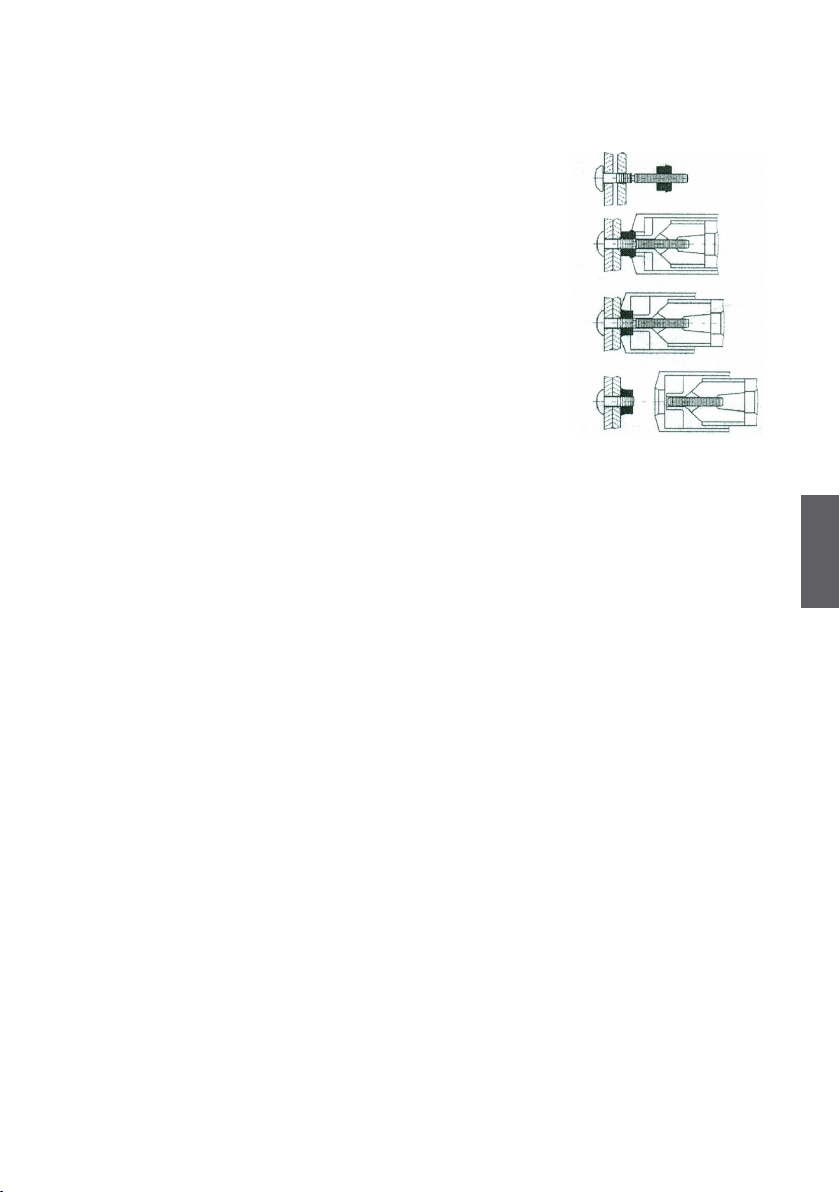
— For processing rivets, use the recom-
mended pulling head for lockbolts or
jaw case and nosepiece for structural
blind rivets accordingly.
— Always use personal protective clothing.
— Tool not in current use must not be con-
nected to the compressed air supply
— Use the tool only for riveting
— Do not use the tool without assem-
bled rubber cover (5).
— The riveting tool must not be carried
or lifted by the air hose
ATTENTION!
Make sure that the riveting tool is
always equipped with the rubber cover
(5) for catching the rivet mandrels, other-
wise there is a high risk of injury.
NOTE
The Manufacturer bears no liability for
damages incurred due to incorrect repair
or due to using spare parts from other
sources.
The warranty is deemed invalid in case
of any repairs have been performed on
the riveting tool, leading to the damage
of the riveting tool or the seals.

7
5
6
2
4
1
3
RL75-2 / Manual
Titgemeyer / 10344EN1121 / 1
English
6. Basic tool equipment
Overview of RL75-2 basic tool
equipment
1. Air connection
2. Balancer suspension attachment
3. Screw for oil rell
4. Trigger
5. Rubber cover
6. Adapter
7. Commissioning
Check the riveting tool visually before
commencing any work
— For visible damages
— For oil leaks
Select the correct pulling head unit for
the used lockbolt or the recommended
conversion kit and nosepiece when pro-
cessing structural blind rivets.
Check that assemblies are installed cor-
rectly and tightened rmly.
After connecting to the air supply check
for exhausting air
Test of the tool function without rivets
prior processing –20 times
(Tool operation)

8
RL75-2 / Manual
Titgemeyer / 10344EN1121 / 1
English
8. Tool operation
— Check the tool operation after ins-
pection or before rst use
(commissioning)
— Always make sure that you are using
a recommended pulling head for the
used rivet. Note that pulling heads
might provide specic adaptions and
sizes. To choose the correct adapter
to t this tool, refer to the table in
chapter 11: “Pulling heads”
— Connect the tool to the air supply (6
– 7 bar)
— To avoid damage to the tool, caused
by exceeded air pressure, the integra-
ted safety valve will switch to release
air. In this case, adjust the air pressure
to the correct value.
— Check for correct assembly and t of
the quick connectors – no air dischar-
ge is audible
— Press the riveting trigger – the rive-
ting tool performs the pulling move-
ment (gripping, pulling, ripping and
releasing of the mandrel)
— After riveting, release the trigger.
The riveting unit automatically
returns to the starting position
Connecting the tool
with the air supply

9
1
2
3
4
RL75-2 / Manual
Titgemeyer / 10344EN1121 / 1
English
Procedure for processing lockbolts
1. Choose the correct lockbolt and collar
according to your application.
2. Make sure the tool and the installed
pulling head is suiting the setting
requirements for the chosen lockbolt
system.
3. Insert the lockbolt into the premanu-
factured holes, in the components that
will be fastened and slide the collar
on the bolt from the other side. (1)
4. Slide the riveting head on the lockbolt
until the head pushes the collar tightly
to the backside of the component. (2)
Make sure that the head of the lock-
bolt is still touching the component
from the other side.
5. Press the trigger and keep it pushed
until the end of the process.
— The jaws grab the mandrel and pull
the lockbolt. (3)
— The nosecap moves towards the
component, builds up the clamping
force, deforms the collar and rips the
mandrel at the end of the process. (4)
6. Release the trigger and make sure
that the ripped mandrel is ejected out
of the tool

10
1
2
3
RL75-2 / Manual
Titgemeyer / 10344EN1121 / 1
English
Procedure for using blind rivet
1. Make sure that the stroke and force
of the tool is sufcient for the chosen
structural blind rivet
2. Choose the recommended nose piece
for the chosen rivet
3. Push the mandrel of the blind rivet
in the nosepiece until it touches the
rivet head. Then push the rivet into
the premanufactured holes of the
components (1)
4. Press the trigger and hold it down
— The mandrel will be pulled and
deforms the rivet according to its
build (2)
—
The rivet is assembled as soon as
the mandrel is ripped by the conti-
nuing pulling force of the tool (3)
5. Release the trigger and make sure
that the ripped mandrel is ejected out
of the tool.

11
RL75-2 / Manual
Titgemeyer / 10344EN1121 / 1
English
9. Proper use
To ensure that all the corresponding
safety measures are observed and that
the riveting tool will work properly, the
following is required:
— The system has to be used in compli-
ance with the tool’s technical data and
specications concerning the use, as-
sembly, connection, environment and
work conditions. These conditions are
stipulated in the documents related to
the order, user information (tags etc.)
and in the documentation delivered
with the system, which includes the
operating instructions, as well as the
maintenance and inspection instruc-
tions in this manual.
— The users have to act in compliance
with local and system-specic condi-
tions and pay corresponding attention
to the operating hazards and speci-
cations.
— All measures required for the main-
tenance of the tool, e.g. transport and
storage, as well as the requirements
for maintenance and regular inspec-
tion must be observed.
— Use only a safety quick coupler for
permanent connection to the com-
pressed air sources
— Always set the riveting tool at the
right angle (90°) to the assembly
surface
— Consider range of use of the selected
rivet.
Compressed air supply
— For correct operation of the device,
it is necessary to observe the range
of inlet air pressure between the
minimum and maximum permissible
value of 6 – 7 bar. If necessary an
appropriate pressure reduction valve
has to be used. In case of non-com-
pliance, personal injury or damage to
the device may occur.
— The pressure regulator must be equip-
ped with a lter unit for separating
dirt and condensate from the air sup-
ply. In case pressure regulator with
a lter unit will not be used, it must
be ensured that the compressed air
cannot contain dirt and condensate.
— Length between the air supply pres-
sure regulator and the tool must not
exceed 3m.
— Used supply line must be resistant to
oil, liquids and operating conditions
— Used air hoses must have a 6 mm
minimum inner diameter.
— Maximum force depends on complian-
ce of the air inlet pressure

12
RL75-2 / Manual
Titgemeyer / 10344EN1121 / 1
English
Air quality classes
under ISO 8573-1
Solid particles Water Oil
Maximum
size
µm
Maximum
concentration
mg/m3
Maximum
pressure dew point
°C
Maximum
concentration
mg/m3
2 1 1 -40 0.1
10. Requirements for compressed air
modication
ISO 8573-1
Note: The stated maximum concentrations relate to 1 bar abs., +20°C and 60%
relative humidity. The individual concentrations are proportionally higher when the
pressure is higher than atmospheric pressure.

13
RL75-2 / Manual
Titgemeyer / 10344EN1121 / 1
English
11. Pulling heads
To install the pulling heads, always
follow the assembly instructions. Instal-
lation may vary depending on the used
pulling head.
The RL75-2 tool contains a pre-moun-
ted adapter, which can be used to mount
the Howmet® pulling heads as specied
in the brochure. For assembly, please
follow the instructions (Chapter 17:
Inspection and Maintenance).
Always make sure that you are using the correct nosecap for the used rivet.
Type Rivet
diameter
Material Pulling head Adapters
Lockbolts Standart lockbolts 4.8
6.4
Aluminium/steel/stainless
99-3003 L
99-3006 L
X
X
Multigrip 4.8
6.4
Aluminium/steel
Aluminium
99-1456
99-1477 UK
X
X
Tainer 9.5 Steel 99-3465
87-0294
87-0818
87-0817
DeltaBolt 4.8
6.4
Steel
Steel
99-3003 L
99-3006 L
X
X
Blind rivets MAGNA-LOCK,
MAGNA-BULB
4.8
6.5
Aluminium/steel/stainless
99-3303
99-3305
X
X
TIBULB 4.8
6.4
7.8
Aluminium/steel/stainless
99-3303
99-3305
87-0294
X
X
87-0817
Pulling heads that can be used with the
RL75-2 riveting tool

14
RL75-2 / Manual
Titgemeyer / 10344EN1121 / 1
English
12. Riveting Tool Storage
After the rst use
If you are not going to use the riveting
tool any further, place it in the original
packaging and store it in a dry and dust
free environment.
After long-term storage
After long-term storage (about 3 years),
replace the hydraulic oil before use. The
hydraulic oil may only be replaced by a
trained expert, according to the opera-
ting instructions. If required, you can
contact the Titgemeyer service centre
for a professional service.
13. Transport Instructions
The tool is delivered completely assem-
bled. It has to be handled like a fragi-
le equipment. This product contains
hydraulic oil.
14. Requirements for Operators
All planning, assemblies, installations,
activations, maintenance and repairs
may only be performed by trained staff
and inspected by technical experts. Trai-
ning may be provided by the manufac-
turer by agreement.
The persons responsible for labour safe-
ty must ensure the following:
— All works related to safety are only
performed by qualied staff.
— The staff must be qualied on the
basis of their specialization (training,
education, experience) or on the basis
of their knowledge of corresponding
standards, specications, accident-
prevention regulations and system
properties. It is essential that such
persons are capable of identifying
and avoiding any potential risks in
timely manner.
15. Tool Modications
No structural modications that could
make safety worse may be performed
on the tool without the manufacturer’s
consent. Any unprofessionally perfor-
med repairs and the use of incorrect
spare parts are deemed to be inter-
ference in the design of the tool; the
manufacturer cannot guarantee the
correct function of the tool or provide
warranty to the product in such cases.
The warranty does not apply to the tool
with damaged seals.

15
RL75-2 / Manual
Titgemeyer / 10344EN1121 / 1
English
Risk of injury in case of incorrect
manipulation!
Working with this tool may not be
dangerous for the operator, when the
regulations in this manual will be read,
understood and followed. The operator
must follow the operations described
in this document. The maintenance and
service work that is not described in
these operating instructions may only
be performed by trained experts who
are trained by TTA.
16. Inspection Plan
Intervals of inspection plans
— Daily inspection
— Check for oil leaks
— Check for unexpected air exhaus-
tion
— Check if the tool works well and
performs a correct setting process
— Check if the pulling head is worn –
in case of visible wear replace the
nosecap/ jaws
— Check that the rubber cover (5) is
assembled correctly
— Stop using the tool immediately
when you notice any sign of a fault
— Weekly inspection/ or after 5000 cycles
— Check the pulling head and jaws,
clean the tool and replace the da-
maged and worn parts
— Rell the oil, if necessary
— Complete inspection made by authori-
sed person (or by producer) once per
year/ or after 500 000 cycles
— Complete check and service of the
tool mechanism
—
Inspection and change any worn parts
— Perform oil change
Do not use any highly active cleaning
agents or ammable liquids when
cleaning!
The riveting tool must be cleaned and
checked in case of any mechanical
defects as for the corresponding type of
application. After the riveting tool has
been cleaned to be stored for a longer
period of time, all external metal parts
need to be lightly greased with corro-
sion inhibitor.

16
B
A
65432
1
RL75-2 / Manual
Titgemeyer / 10344EN1121 / 1
English
17. Inspection and Maintenance
Adapters consist of:
1. Nozzle lock
2. Adapter for hydraulic piston
3. Adapter for nosecap
4. Ring
5. Shaft retaining ring
6. Counter nut
Changing of pulling heads
— Disconnect the tool from the compres-
sed air supply
— Disassemble the counter nut (6) and
remove the nosecap
— In case of using a TTA pulling head,
mount the jaw case with the jaws on
the hydraulic piston and nosecap on
the tool
— In case of using a Howmet® pulling
head please refer to the instructions
below
Assembly of Howmet® pulling heads
Mount tension head (99-3303; 99-3305)
Before mounting the tension head, make
sure that you have chosen the right
tension head
The assembly is identical for the tension
heads listed.
The tension head 99-3303 is displayed
in the illustrations.
— Disconnect from compressed air
connection.
— Disassemble whole front setup of the
tool (1,2,3,4,5,6)
— On the standard adapter for hydrau-
lic piston (2) mount the jaw case (A)
without Howmet® spacer and tighten
both parts on the tool
— Mount the adapter for the nose cap
(1,3,4,5) on the tool
— Slip nose cap (B) over the jaw case and
push into the nose cap up to the limit.
— Slip counter nut (6) over the nose cap,
screw onto the adapter for nose cap
and screw hand tight.

17
C
D
b
F
a
E
RL75-2 / Manual
Titgemeyer / 10344EN1121 / 1
English
Mount tension head (99-3003; 99-3006;
99-1456; 99-1477UK)
Before mounting the tension head, make
sure that you have chosen the right
tension head
The assembly is identical for the tension
heads listed.
The tension head 99-3003 is displayed
in the illustrations.
— Loosen compressed air connection.
— Disassemble whole front setup of the
tool (1,2,3,4,5,6)
— On the standard adapter for hydrau-
lic piston (2) mount the jaw case (C)
without Howmet® spacer and tighten
both parts on the tool
— Mount the adapter for the nose cap
(1,3,4,5) on the tool
— Slip nose cap (D) over the jaw case (C)
and push into the nose cap up to the
limit.
— Slip counter nut (6) over the nose cap
(D), screw onto the adapter for nose
cap and screw hand tight.
Rivet Head Assembly (99-3465)
Before mounting the tensioning head,
make sure that you have chosen the
right tension head
Adapters from kit 87-0818 are required
for this assembly
— Disconnect the compressed air connection.
— Disassemble whole front setup of the
tool (1,2,3,4,5,6)
— On the standard adapter for hydrau-
lic piston (2) mount the jaw case (E)
without Howmet® spacer and tighten
both parts on the tool
— Assemble the nose cap adapter (a) from
kit 87-0818 to the tool and secure with
parts from standard adapter (1,4,5)
— Insert the washer (b) between the
adapter on the nose cap (a) and attach
the nose cap (F)

18
H
c
d
G
RL75-2 / Manual
Titgemeyer / 10344EN1121 / 1
English
Rivet Head Assembly (87-0294)
Before mounting the tensioning head,
make sure that you have chosen the
right tension head
Adapters from kit 87-0817 are required
for this assembly
— Disconnect the compressed air con-
nection.
— Disassemble whole front setup of the
tool (1,2,3,4,5,6)
— Mount the adapter for the hydraulic
piston (c) from the set 87-0818 and
then mount jaw case (G) and tighten
both parts on the tool
— Assemble the nose cap adapter (d)
from kit 87-0817 to the tool and se-
cure with parts from standard adapter
(1,4,5)
— Assemble nose cap (H)
Oil relling
— Oil needs to be relled when the wor-
king stroke is reduced during working
process
— During oil relling, prevent dirt from
entering the hydraulic system
— Disconnect the tool from the com-
pressed air
— Remove the nosecap (see chapter
jaws cleaning and replacement)
— Use allen key no. 4 to unscrew the
screw in the top of the tool
— Fill up the syringe with the recom-
mended hydraulic oil (chapter 19.
Technical parameters), attach it to the
brass adapter and screw the adapter
on the outlet
— Press the hydraulic oil into the tool
and pump the syringe piston several
times. As you are pumping, you can
see that the hydraulic piston is mo-
ving forward and backwards.
— Unscrew the adapter, mount the screw
and USIT ring, mount the nosecap (see
chapter jaws cleaning and replace-
ment)
— Clean the tool from any spilled oil
— Activation of the tool without rivets -
20 times (Tool operation)

19
RL75-2 / Manual
Titgemeyer / 10344EN1121 / 1
English
18. Troubleshooting
The operator must ensure the following:
— Customer’s maintenance staff can be
notied immediately and at any time
during the work.
— The maintenance staff is qualied to
properly respond to the failure of the
riveting tool and the failure of related
systems.
— The failures are analysed by qualied
staff, any defects are repaired and the
operation is optimised in a way that
prevents any similar failures in the
future.
Total weight (according to the
version)
1,71 kg
Dimensions (HxL) 331 x 218 mm
Blind rivet diameter
Lockbolts
6,4 mm
5 – 6,5 mm
Tractive force 28 kN / 6 bars
Stroke 17 mm
Speed of riveting cycle 0,9 s
Air consumption 5,8 l [ANR]
Noise level 86 dB
Operating pressure 6 bars, max. pressure 7 bar
Compressed air connection 6 mm (G 1/4“)
Hydraulic oil standard ISO HN 32
Hydraulic oil example OH-HM 32
Lubricant standard ISO XCCHB-2
Lubricant example LV2EP
19. Technical parameters

20
RL75-2 / Manual
Titgemeyer / 10344EN1121 / 1
English
maintenance, alteration or modication
in any way by anyone other than Tit-
gemeyer GmbH & Co. KG, or its authori-
zed service centres, are excluded from
coverage.
Should this tool fail to meet the war-
ranty, promptly return the tool to our
Titgemeyer GmbH & Co. KG service cen-
ter or factory authorized service centre
location nearest you.
Titgemeyer GmbH & Co. KG will then
replace, free of charge, any part or
parts found by us to be defective due
to faulty material or workmanship, and
return the tool repaired. This represents
our sole obligation under this warranty.
In no event shall Titgemeyer GmbH &
Co. KG be liable for any consequential
or special damages arising out of the
purchase or use of this tool.
22. Package Contents
— 1 x riveting tool
— 1 x Allen key no. 4
— 1 x syringe
— 1 x adapter
20. Disposal of the Riveting Tool
Disposal of the tool in compliance with
the directives valid for EU. Check for
hydraulic oil inside the riveting tool.
Remove it and dispose of the oil in an
environmentally friendly manner.
21. Warranty
Titgemeyer GmbH & Co. KG provides a
12- month warranty from the date of
purchase. The warranty does not cover
consumables (jaws, nosepieces, man-
drels, etc.)
Titgemeyer GmbH & Co. KG warrants
that all power tools have been carefully
manufactured and that they will be free
from defect in material and workmans-
hip under normal use and service for
a period of one (1) year. This warranty
applies to the rst time purchaser of the
tool for original use only.
Exclusions: Normal wear and tear. Perio-
dic maintenance, repair and replacement
parts due to normal wear and tear are
excluded from coverage. Abuse & misu-
se. Defect or damage that results from
improper operation, storage, misuse or
abuse, accident or neglect, such as phy-
sical damage are excluded from cover-
age. Unauthorized service or modica-
tion. Defects or damages resulting from
service, testing adjustment, installation,
Table of contents
Other Titgemeyer Rivet Tools manuals

Titgemeyer
Titgemeyer RL60-2 User manual

Titgemeyer
Titgemeyer TIOS HN12 PT User manual

Titgemeyer
Titgemeyer RL20-2 User manual

Titgemeyer
Titgemeyer MS 50 User manual

Titgemeyer
Titgemeyer RIVETEC RL 75 User manual

Titgemeyer
Titgemeyer MS 40A User manual

Titgemeyer
Titgemeyer RIVETEC RL 50 User manual

Titgemeyer
Titgemeyer RL100-2 User manual

Titgemeyer
Titgemeyer RL50-2 User manual