JST CMKS-L INDUSTRY STANDARD APPLICATOR
H:\0 - Quality Documents\2 Department\Tech Serv\Application tooling\Applicators and Die sets\TS174-00
CMKS-L Manual.doc
1. APPLICATOR RAM SLIDE
1-1 SLIDE ASSEMBLY
The conductor dial (108) and the insulation dial (111) are fixed by the shank (112).
To remove the two disks you must first loosen the 4mm grub screw positioned in the
main body of the slide, now by loosening the shank you can remove both wire disks.
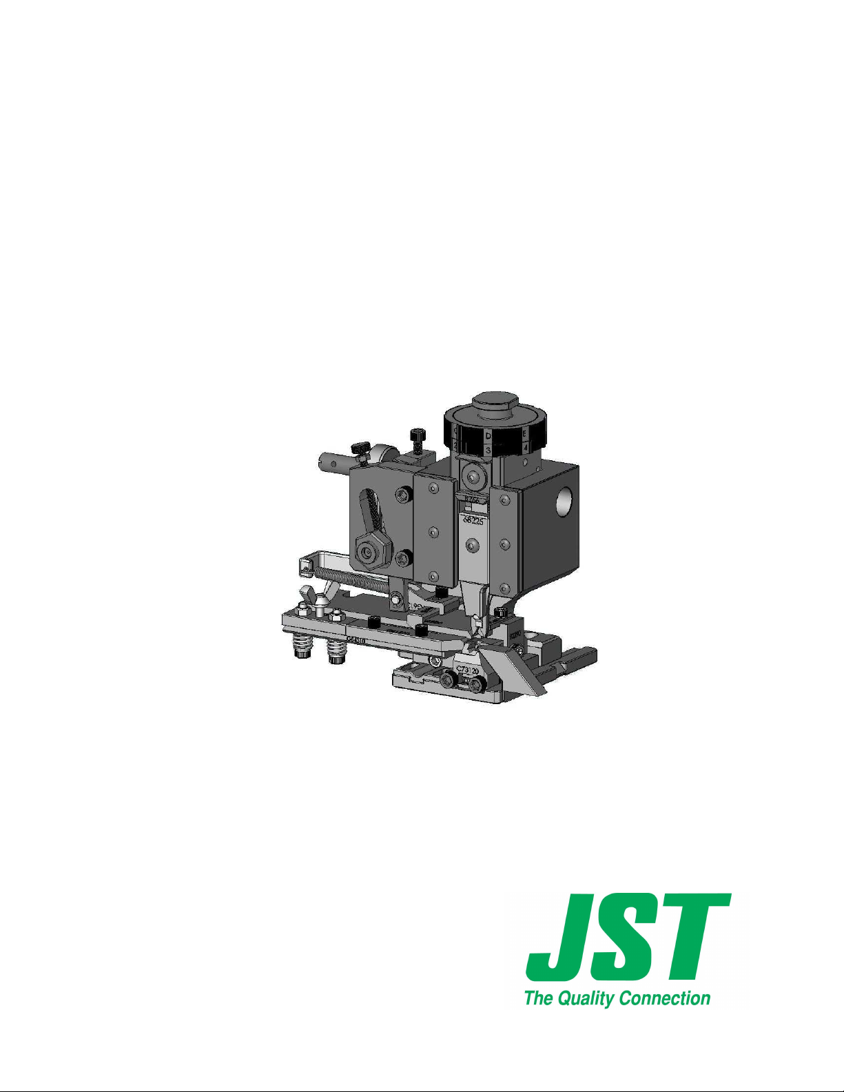
Positioned in the rear of the slide is the cam (119). There are two different cams
available for this applicator. The first type is an pre-feed cam, with this cam fitted
the terminal is present over the anvil when the press is at top dead centre, this type of
cam is commonly used when the applicator is located in a bench press. The other
type is a post-feed cam, this operates in the opposite manner, which means the
terminal feeds forward as the press travels to bottom dead centre, this type of cam is
commonly used when the applicator is located in a fully automatic machine.
1-2 TROUBLE SHOOTING
The dials are difficult to turn
1. Dismantle slide assembly as described above and check for any foreign bodies.
2. Ensure 3mm grub screw located in the insulation dial is not excessively
tightened.
3.
Check condition of the positioning Pin (109).
The dials turn freely but do not locate in position correctly
1. Check the condition of the positioning spring (110) and the positioning pin
(109). The Spring may be broken.
2.
Ensure 3mm-grub screw located in the insulation dial is adjusted correctly.
2. EJECTOR
2.1 PURPOSE
After the terminal has been successfully crimped on the wire, the terminal may
adhere to the punches; the ejector assures the function of stripping the terminal
from the punches.
2.2 ASSEMBLY
Place the ejector punch with relevant spring (159) into the corresponding slot of
ejector holder (160) ensuring the ejector slides freely up and down when fixed into
position on the front of the crimping punches.