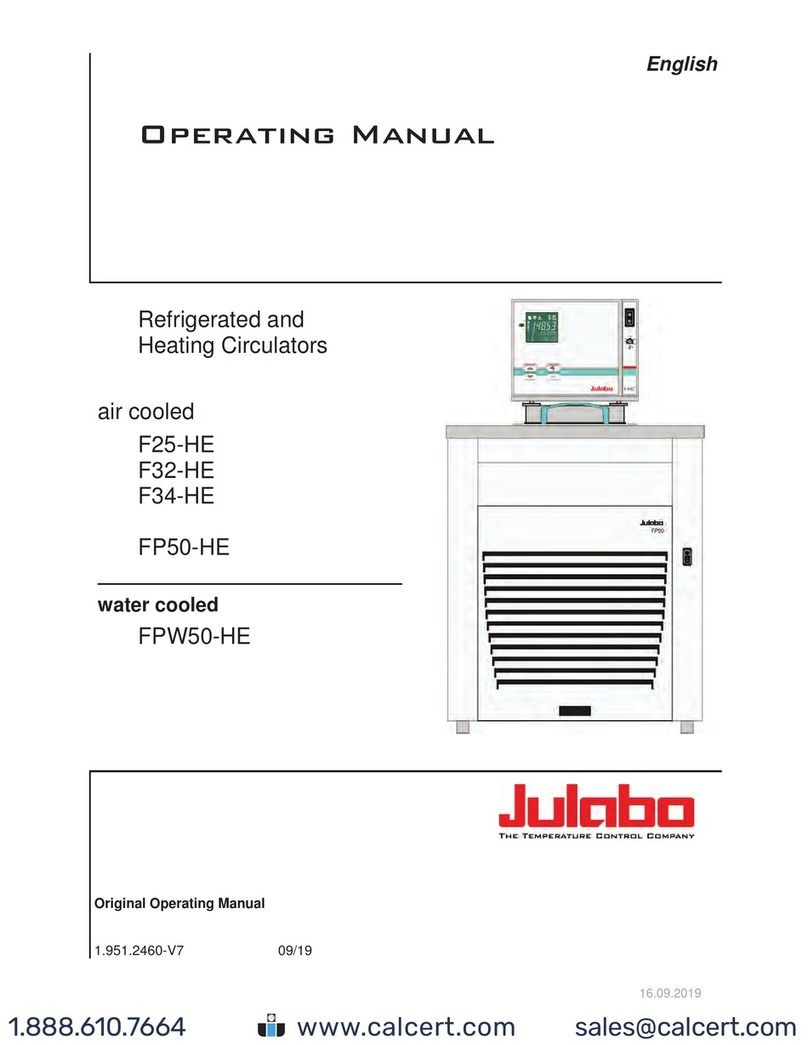
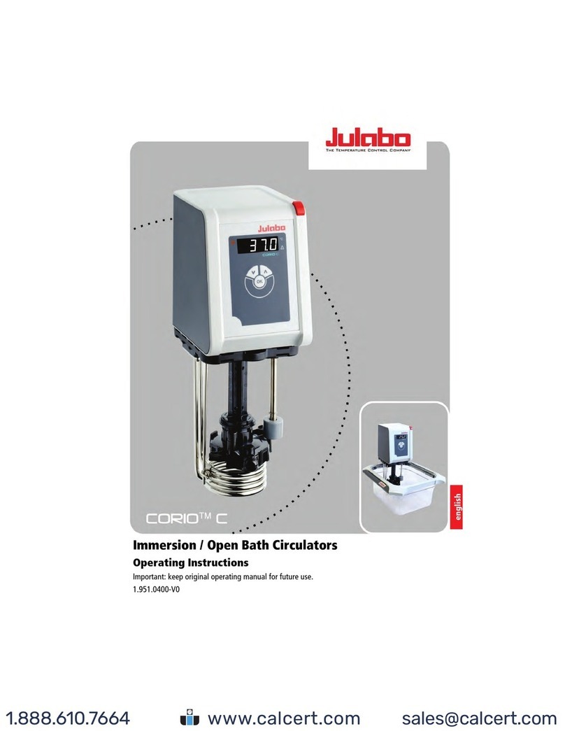
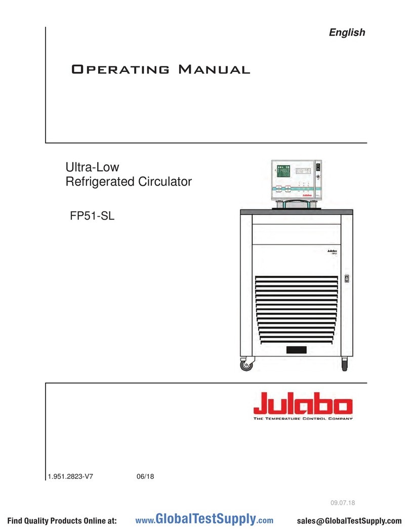
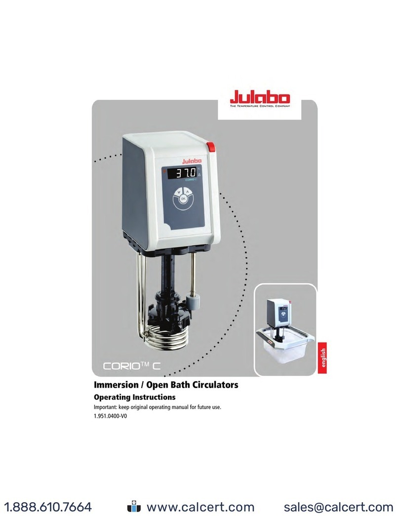
Julabo Corio C Installation instructions

Heating immersion circulator, open bath heating circulator,
refrigerated circulator
Original operating manual
1.950.0400.en.V05 12/2022
www. .com information@itm.com1.800.561.8187

2
Legal
The content of this operating manual isprotected bycopyright. Information,
including texts, images, and other contents maynot bereproduced, distributed,
transmitted, stored or otherwise used inany form without prior explicit written
consent.
Illustrations in this operating manual are for illustrative purposes and are not
necessarily displayed toscale.
www. .com information@itm.com1.800.561.8187

3
1Foreword ............................................................................................. 5
2About this manual.............................................................................. 6
2.1 Original JULABO spare parts.......................................................... 6
2.2 Accessories..................................................................................... 6
2.3 Warnings ......................................................................................... 7
2.4 Symbols used.................................................................................. 8
3Intended use ....................................................................................... 8
4Safety................................................................................................... 9
4.1 Safety instructions........................................................................... 9
4.2 Safety symbols.............................................................................. 11
4.3 Safety function............................................................................... 11
5Product description.......................................................................... 12
5.1 Product overview........................................................................... 12
5.2 Operating and functional elements ............................................... 13
5.2.1 Key description......................................................................... 14
5.3 Alarm messages............................................................................ 14
5.4 Technical data............................................................................... 15
5.4.1 Material of parts that come into contact with the medium........ 17
5.4.2 Bath fluids................................................................................. 17
6Transport and installation ............................................................... 18
6.1 Transporting the device.................................................................18
7Initial operation................................................................................. 19
7.1 Connect the device to the power supply.......................................19
7.2 Fill device ...................................................................................... 19
8Operation........................................................................................... 20
8.1 Switch on the unit.......................................................................... 20
8.2 Switch off the unit.......................................................................... 20
8.3 Configuring setpoint temperature.................................................. 20
8.4 Start temperature control application ............................................ 21
8.5 Activate autostart function.............................................................21
8.6 Setting the timer ............................................................................ 22
8.7 Adjusting the temperature sensor (ATC).......................................22
www. .com information@itm.com1.800.561.8187
4
9Maintenance......................................................................................23
9.1 Check safety symbols....................................................................23
9.2 Test the low liquid level safety function.........................................23
9.3 Replace detachable power cord....................................................24
9.4 Emptying........................................................................................24
9.5 Clean device..................................................................................25
9.6 Device storage...............................................................................25
9.7 Technical Service..........................................................................26
9.8 Warranty........................................................................................26
10 Disposal.............................................................................................27
10.1 Device disposal .............................................................................27
11 EC Declaration of Conformity .........................................................28
12 UK Declaration of Conformity.........................................................29
13 Appendix ...........................................................................................30
13.1 Alarms and Warnings....................................................................30
www. .com information@itm.com1.800.561.8187
Foreword
5
1 Foreword
Congratulations!
You have made an excellent choice.
JULABO would like to thank you for the trust you have placed in our company
and products.
This operating manual will help you become acquainted with the use of our
units. Read the operating manual carefully. Keep the operating manual handy at
all times.
www. .com information@itm.com1.800.561.8187
About this manual
6
2 About this manual
This manual is intended for the equipment specified on the cover page.
NOTE
Observe the safety instructions!
Read the Safety section of this manual before using the equipment for the
first time.
2.1 Original JULABO spare parts
Hassle-free continuous operation and safety also depend on the quality of the
spare parts used.
Only original JULABO spare parts guarantee the highest possible quality and
safety. Original JULABO spare parts are available directly from JULABO or your
specialist dealer.
Please note that JULABO cannot provide a warranty service if non-original
JULABO spare parts are used.
2.2 Accessories
JULABO offers a wide range of accessories for the devices. Accessories are not
described in this manual.
www. .com information@itm.com1.800.561.8187

About this manual
7
2.3 Warnings
The manual contains warnings to increase safety when using the device.
Warnings must always be observed.
A warning sign displayed in signal color precedes the signal word. The signal
word, highlighted in color, specifies the severity of the hazard.
DANGER
This signal word designates a danger with a high level of risk which, if it not
prevented, will result in death or serious injuries.
WARNING
This signal word designates a danger with a medium level of risk which, if it
not prevented, may result in death or serious injuries.
CAUTION
This signal word designates a danger with a low level of risk which, if it not
prevented, may result in minor to moderate injuries.
NOTE
This signal word designates a possibly harmful situation. If it is not avoided,
the system or objects in its vicinity may be damaged.
www. .com information@itm.com1.800.561.8187
Intended use
8
2.4 Symbols used
Various symbols are used throughout this manual to aid reading
comprehension. This list describes the symbols used.
Tools needed for the following approach
Prerequisite to be met for the following procedure
1. Numbered action steps
Interim result for individual action steps
Additional note for individual action steps
Final result of a procedure
<> Terms in angle brackets denote control menu
[] Terms in square brackets denote keys, softkeys and buttons
3 Intended use
This section defines the purpose of the unit so that the operator can operate the
unit safely and avoid misuse.
JULABO heating immersion circulators and open heating bath circulators are
designed to control water temperature. Samples in suitable tanks can be
temperature-controlled.
These devices are not suitable for direct temperature control applications for
food, other consumables, or pharmaceutical or other medical products.
Do not use bath fluids other than water, as this is not in accordance with the
device's intended use.
These devices are not suitable for use in explosive environments.
These devices are not intended for use in living areas. They may cause
interference with radio reception.
www. .com information@itm.com1.800.561.8187
Safety
9
4 Safety
4.1 Safety instructions
The unit is built in accordance with state of the art technology and recognized
safety regulations. Despite this, its use may pose a risk to life and limb for the
user or third parties.
Therefore, always read and observe the following safety instructions before
using the product.
Hot surfaces!
The following parts and elements may become hot during operation:
–Bath fluid
–Heating element
–Bath lid
–Bath surface
–Connections for external application
Contact may cause severe burns or scalds to hands and arms, face and limbs.
•Keep sufficient distance from hot surfaces and fluids.
•Wear suitable protective gloves.
Electric shock from electrical system!
Touching damaged live parts can cause severe electric shocks and lead to injury
or even death.
•Have damaged insulation and parts of the electrical system immediately
repaired by JULABO service technicians or a qualified specialist workshop
•Immediately replace damaged power cords
•When connected with a mains plug, this mains plug must always be readily
accessible
Wear personal protective equipment!
Lacking or unsuitable personal protective equipment increases the risk of health
damage and injury.
Personal protective equipment includes, for example:
–Work gloves
–Safety shoes
-Protective clothing
–Breathing protection
-Hearing protection
–Face and eye protection
www. .com information@itm.com1.800.561.8187
Safety
10
•Specify and provide personal protective equipment for the respective
application.
•Use only personal protective equipment that is in good condition and
provides effective protection.
•Adapt personal protective equipment to the person, e.g., by size.
Keep safety symbols legible!
Safety symbols on the unit warn of dangers in hazardous areas and are an
important part of the unit’s safety equipment. Missing safety symbols increase
the risk of injury to persons.
•Clean dirty safety symbols.
•Replace damaged and unrecognizable safety symbols immediately.
Maintenance and repair work!
Improper maintenance and repair work jeopardizes operational safety. This can
result in serious injury or death.
•Only carry out work described in this operating manual. Switch off the unit
and disconnect itfrom the power supply before carrying out any work.
•All other maintenance and repair work mayonlybecarried out bya service
technician or a qualified specialist workshop.
www. .com information@itm.com1.800.561.8187
Safety
11
4.2 Safety symbols
There are safety symbols included with the device, which should be attached to
the device before initial operation.
Safety
symbols
Description
Warning of a danger zone. Note operating manual
Warning about hot surface
Warning of cold surface
Read operating manual before switching on
4.3 Safety function
Technical protective devices provide for safe operation. If a safety function is
triggered, the operator is alerted with a message on the display and an acoustic
signal.
Overheating protection
The overheating protection prevents overheating of the heater.
•The protective mechanism is triggered when the device recognizes a
temperature difference of more than 20 K between the working
temperature sensor and the safety temperature sensor. Am error message
appears on the display. A restart is required.
www. .com information@itm.com1.800.561.8187
Product description
12
Low liquid level protection
A level switch recognizes when the bath fluid fill level in the bath tank is too
low. The unit has a warning system to prevent overheating of the heater or dry
running of the pump.
•The low liquid level alarm is triggered when the float reaches its lower limit
stop. The device switches off the pump and heater. A continuous signal
tone sounds. An error message appears on the display. A restart is required.
Produc t descr ipti on
5 Product description
Produc t overvi ew
5.1 Product overview
The circulators can be combined with various baths with volumes of up to 30 l.
Depending on the device combination and accessories used, the circulators work
in a temperature range from +20°C to +100°C.
Heating immersion circulator Open heating bath circulator
CORIO C circulator for bath tanks up
to 30 l.
Circulator with transparent bath
tank. Example: CORIO C-BT9.
www. .com information@itm.com1.800.561.8187

Product description
13
5.2 Operating and functional elements
The following figure shows the operating and functional elements and their
position on the unit.
Fig. 1: Control and function elements
1 Mains switch
2
Heating control LED
3 LED display
4 Alarm control LED
5 Keypad with display
6 Service key (covered)
7 Mains fuse, resettable
8 Mains fuse, resettable
9 Mains connection
www. .com information@itm.com1.800.561.8187

Product description
14
5.2.1 Key description
The device is operated using the key panel. This is used to control all menu
functions and make entries.
Key Function
Press [OK] to start a temperature control application or to
stop a running temperature control application.
Press [OK] to enable a selected function, open a menu
option, or confirm a set value.
Use the arrow keys to select a function or set a value. Short
press for single steps, press and hold for fast counting.
5.3 Alarm messages
Alarms and warnings are indicated on the display using error codes. Important
error code descriptions can be found in the appendix. If you are unable to rectify
a fault, contact Technical Service.
Alarm:
In the event of an alarm, the control LED lights up. The temperature control is
stopped. At the same time, a continuous acoustic signal sounds and an error
code is shown on the display. The acoustic signal can be deactivated by pressing
the [OK] key. The fault causing the alarm must be remedied. A restart is
required.
Warning:
In the event of a warning, the temperature control application is not interrupted.
A signal tone is emitted at intervals. The display alternates between the actual
temperature and the error code. The acoustic signal can be deactivated by
pressing the [OK] key. If the underlying cause of the warning is remedied, the
signal tone ceases. Depending on the cause, warnings may cease automatically
after a period of time, e.g. when the device cools down.
www. .com information@itm.com1.800.561.8187

Product description
15
5.4 Technical data
Performance specifications measured in accordance with DIN12876.
Performance specifications apply at an ambient temperature of 20°C.
Grouping of the device acc. to CISPR 11:
•The device is an ISM device of group 1, which uses high frequency for
internal purposes
•Class A: Use in an industrial electromagnetic environment
In accordance with IEC 61010-1, the device is designed for safe operation under
the following ambient conditions:
•Indoor use
•Altitude up to 2000 m above sea level
•Ambient temperature +5 … +40°C
•Maximum relative humidity 80% for temperatures up to 31°C, decreasing
linearly down to 50% relative humidity at 40°C
•Mains voltage fluctuations up to ±10% of the nominal voltage permissible
if not otherwise specified
•Pollution degree level 2
Protection class according to EN 60 529:
•Protection class IP21
www. .com information@itm.com1.800.561.8187

Product description
16
CORIO C
Temperature control application
Working temperature range °C +20 … +100
Temperature stability °C ± 0.03
Temperature resolution °C 0.01
Temperature control PID1
Temperature setting Digital
ATC sensor adjustment 1-point adjustment
Pump
Volume flow rate at 0 bar l/min 6
Supply pressure at 0 l bar 0.1
Maximum viscosity cSt 1
Dimensions
Dimensions (W x D x H) cm 13.2 x 16.0 x 36.2
Immersion depth cm 16.6
Weight kg 1.9
Display
Display LED
Performance data
Mains connection 100-115 V, 50/60 Hz 230 V, 50/60 Hz
100 V
50/60 Hz
115 V
60 Hz
230 V
50/60 Hz
Current consumption A 8 10 9
Heating capacity kW 0.8 1.0 2.0
Mains fuse, resettable A 15
www. .com information@itm.com1.800.561.8187

Product description
17
5.4.1 Material of parts that come into contact with the medium
The table lists parts that could come into contact with the bath fluid as well as
the material that the parts are made of. This data can be used to check the
compatibility of the parts with the bath fluid used.
Parts that come into
contact with the medium
Material
Motor 1.4301
Pump PPS
Heating element 1.4404/316L
Inbuilt temperature sensor
Pt100
1.4571
Connection of temperature
sensor
1.4301
Float 1.4401
Float pipe 1.4571
Hose olive 1.4301
Single-ear clamp 1.4301
Hose FPM/FKM
5.4.2 Bath fluids
Only water with an electrical conductivity of 0.1 to 50 µS is permitted as bath
fluid.
NOTE
No liability accepted for usage of bath fluids that are not
suitable!
Unsuitable bath fluids that are not approved by JULABO can damage the
water bath.
•Use bath fluids that are recommended by JULABO
•Before filling, check the parts that are in contact with the medium for
compatibility with the bath fluid
•Do not exceed the maximum permissible viscosity during operation
•Consult JULABO before using a bath fluid other than the recommended
one
www. .com information@itm.com1.800.561.8187

Transport and installation
18
Water as bath fluid
•Water can be used for working temperatures from +5 °C to +90 °C
•Recommended: Use only ultrapure or distilled water.
•When using ultrapure or distilled water, add 0.1 g Na2CO3per liter of water.
6 Transport and installation
6.1 Transporting the device
This section describes how to transport the device safely.
CAUTION
Burn hazard on the heating element!
The heating element may still be hot even after the device has been switched
off, and may cause burns if touched.
•Allow the device to cool down to room temperature after switching off
•Wear protective gloves
The device is switched off and cooled to room temperature.
1. Disconnect the mains cable from the device.
2. Disconnect the circulator from the bath before transport.
3. Empty the bath.
See the technical data for weight information.
The device can be safely transported to its installation location.
www. .com information@itm.com1.800.561.8187

Initial operation
19
7 Initial operation
7.1 Connect the device to the power supply
This section describes how the circulator is connected as a bridge mounted
circulator or heating circulator.
The circulator is mounted as a bridge mounted or heating circulator.
The power cable is ready for use.
1. Insert the power cable on the back of the circulator into the mains
connection [1].
2. Connect the circulator to the power supply using the power cable.
The circulator is connected.
7.2 Fill device
This section describes how the device should be filled with bath fluid during
initial operation.
Specifications for filling volume can be found in the technical data.
The device is mounted on a bath and switched off.
1. Fill the bath with water.
Maximum filling height 30 mm below the upper edge of the bath.
The bath fluid expands with increasing temperature and can overflow.
With decreasing temperature, the low liquid level protection can be
triggered and interrupt the temperature control process.
2. Place the sample in the bath.
3. If necessary, adjust the level by refilling or draining.
www. .com information@itm.com1.800.561.8187

Operation
20
Once the working temperature has been reached and the sample inserted,
the bath fluid level in the bath tank should cover the heating coil of the
heating circulator.
The unit is filled with bath fluid.
B
8 Operation
8.1 Switch on the unit
This section describes how to switch on the device.
The device is connected and ready for operation.
1. Switch the unit on at the mains switch.
All display elements light up briefly, the software boots and starts the
device.
The device is switched on and ready for operation. The display shows
“OFF”. If the auto start function is activated, then the device starts directly
into the last setting.
8.2 Switch off the unit
This section describes how to switch off the device.
The device is switched on.
1. Stop a running temperature control application.
2. Switch the device off at the mains switch.
The device is switched off.
8.3 Configuring setpoint temperature
Device is running the temperature control application to the configured setpoint
temperature. The factory setting is 10°C. The setpoint temperature can be
changed while the temperature control application is running. The set value is
saved.
The unit is switched on.
1. Press one of the arrow keys briefly.
The display switches from the actual value display to the setpoint display,
then shows the last saved setpoint temperature. The digits before the
decimal point flash.
2. Use the arrow keys to set the value before the decimal point and confirm
with [OK].
www. .com information@itm.com1.800.561.8187
Other manuals for Corio C
3
This manual suits for next models
6
Table of contents
Other Julabo Water System manuals

Julabo
Julabo SL-6 User manual

Julabo
Julabo DYNEO DD Installation instructions

Julabo
Julabo CORIO CD User manual

Julabo
Julabo ED-5A User manual

Julabo
Julabo 9011305.22 User manual

Julabo
Julabo CORIO C-B5 User manual

Julabo
Julabo CORIO CP-1200FW Installation instructions

Julabo
Julabo DYNEO DD-BC4 User manual

Julabo
Julabo F32-HE User manual

Julabo
Julabo 9352751.N.CSA/UL User manual