JUMA TRX-2 User manual

JUMA TRX-2 Operating Manual
5B4AIY Firmware Version 1.07m
The TRX-2 is an all-band QRP transceiver utilising a direct digital synthesiser and employing
quadrature phase-shift detection in a direct-conversion arrangement for both transmission and
reception, and capable of USB/LSB and CW modes of operation.
This document describes the operation and setup of this equipment using firmware version
1.07m, software modifications and changes made by Adrian Ryan, 5B4AIY.
It assumes that you have already performed the various hardware setup adjustments covering
receiver AGC threshold setting, optimisation of sideband suppression, transmitter final
amplifier bias current adjustments, amplifier gain compensation and microphone level setting.
Front Panel Controls
Control Description
PWR
This button is used to power-up and power-down the transceiver, as well as several secondary
functions. To power up the transceiver, briefly press the button. The display will illuminate
and a sign-on message will be displayed:
JUMA-TRX2 v1.07m
OH2NLT OH7SV
After a short delay, the current frequency bands in use will be displayed either as:
IARU Freq Bands
or:
USA Freq Bands
Then the main display will be shown.
1

To power down the transceiver, press and hold the power button, and a message will be
displayed showing a count-down to zero. At this point the display will clear, the backlighting
will be turned off, and the button can be released.
During the count down period the current user settings are being written to the EEPROM. If
the button is released during the count-down, it will be aborted, and the previous operation
will be resumed.
During normal operation, a brief press of the power button will toggle locking the VFO
frequency. Note that this simply disables the VFO tuning knob, the receiver frequency can
still be changed by pressing either the VFO button or using the Rapid Band Switch feature.
The power button is also used to acknowledge and cancel any alarms. If an alarm cannot be
cancelled, then press and hold the power button for 500 mSec and you will enter the
emergency shutdown mode. Release the button and the transceiver will immediately shut off.
In this mode it will bypass saving the user settings in favour of a rapid power down. For full
details of the alarms, please refer to Annex F.
If the power button is pressed and held whilst powering up, the system setup menu will be
selected. The various operations and settings are fully covered in the System Setup section of
this document. To exit the setup menu without making any changes, press and hold the power
button to power the transceiver down.
CW Speed
This knob controls the speed of the internal keyer, or, can be used as a receiver squelch
setting. The operation of this knob is controlled by a setting in the User Configuration menu,
which is covered in the User Configuration section of this document.
MIC
The microphone/PTT switch is connected to this socket by means of a 3.5mm stereo jack.
The wiring is:
Tip : Microphone/Line input
Ring : PTT switch
Screen : Ground/Shield
The PTT switch requires a dry contact closure to ground, or an open-collector connection
capable of sinking 0.5mA from +5V.
The microphone is normally expected to be an electret, and there is a bias voltage of +5V via
a source resistance of 5.7K. If a dynamic microphone is used, a DC blocking capacitor should
be wired in series with the tip connection. Most dynamic microphones have an impedance of
about 400Ω, for optimum speech quality and low frequency response, a capacitor of at least
2µF should be used. If using an electrolytic capacitor, wire the +ve to the tip of the plug.
2

DISPLAY/CONFIG
This multi-function button is normally used to control the transceiver’s display. In the receive
mode the normal display has the S-meter, either as a numeric or graphic indication at the top
left of the screen, followed by the mode indicator, (LSB/USB/CW/Tune), and the receiver’s
filter, Wide (WID), Medium (MID), or Narrow (NAR).
A brief push of the DISPLAY/CONFIG button will over-write the mode and bandwidth with
the PWR display, which is only active during either transmit or tune operations. The next
brief push will display the SWR, again only active during transmit or tune. The third push
will show the current DC input voltage, the next push the transmitter’s final amplifier’s drain
current, also only active in transmit, and finally back to the normal display.
If the button is pressed and held, after a short delay you will be presented with the User
Configuration menu. This is more fully covered in the User Configuration section. To exit
from this menu, press and hold the button until a long beep is heard, then release.
AF GAIN
This is the normal volume control.
MODE
This multi-function button has four functions:
Mode Selection
The primary function is that of selecting the operating mode. A brief push will select in turn
LSB, USB, CW, or the Tune function.
Memory Copy
This function allows you to copy the contents of any active VFO to the User VFO Memory
bank.
To access this function, press and hold the MODE button until you hear a long beep. The
display will alter as shown above. To copy from the active VFO to a memory, rotate the VFO
knob clockwise, the direction arrow will point right, and the right-hand VFO memory
designator will increment. In the example above, the active VFO is A, whose frequency and
mode is displayed on the lower line, and is being copied to VFO memory P.
Copy VFO-A to VFO-P
Copy VFO memory J to active VFOA
3

To copy from a VFO memory to the active VFO, turn the VFO knob anti-clockwise, and the
source will decrement until you get to VFOA. The direction arrow will reverse showing that
the direction of the transfer is from the VFO memory to an active VFO. In the example
above, VFO memory J, whose frequency and mode are displayed on the lower line, is being
copied to the active VFO, A.
When the MODE button is released, the copy operation will be completed.
Fast User Configuration Page Select
As there are now 21 configuration pages, this feature allows you to rapidly select the desired
configuration page. For details, see the User Setting Configuration section.
Reset Defaults
If this button is held and then the transceiver powered up, the system defaults can be restored
without the necessity of using the System Setup facility. With the transceiver off, press and
hold the MODE button, and briefly press the power button. Wait until the screen displays the
message asking whether you wish to restore the factory defaults. Release the MODE button.
A momentary push of the MODE button will restore the defaults, a momentary push of the
FILTER button will abort the selection, and return you to normal operation.
RIT
A brief push of this button will toggle the Receiver Incremental Tune On/Off. When on, the
lower right-hand portion of the screen will display the current offset frequency up to a
maximum of ±1kHz, controlled by the RIT knob.
If the Include RIT feature is enabled in the User Setup, then the frequency display will show
the actual receiver frequency including the RIT shift.
A long push of this button will invoke the Rapid Band Selection feature.
Frequency Display Including RIT Offset
Rapid Band Select In Use
4

If this is invoked, the top line of the display will show the band to be selected, from 160 – 10
metres. If the current receiver’s frequency is within an amateur band, then the selection will
display this band, and the lower frequency display will show the selected frequency. If the
frequency is not within a recognised amateur band, then the out-of-band indicator will show
on the main display, and the 160m band’s frequency will be shown, as illustrated above.
The frequency displayed can be either a default band-centre, or a user stored frequency. These
user frequencies are in addition to those stored in the 26 VFO memories that are also
available, but whereas the VFO memories can store any frequency, the user frequencies can
only be valid amateur band frequencies relative to the current frequency band setting
corresponding to either IARU Region 1, or the US bands.
To select an amateur band, simply rotate the VFO tuning knob which will cycle you through
all the available bands from 160 through 10 metres. When the RIT button is released, the
selected frequency will be used along with the mode stored.
Note that this rapid band switching facility is disabled in both the Split mode of operation and
if the transmitter is keyed either with the PTT switch or a key. It is also inoperative in the
Service and User Configuration modes.
To save a favourite amateur band frequency, please refer to the FILTER button operation.
FAST/VFAST
This button is used to select the various tuning rates that are available. A brief press will cycle
through the Slow (S) Medium (M) and Fast (F) tuning rates, corresponding to tuning rates of
1Hz, 10Hz, and 100Hz.
A long push will select the Very Fast (V) tuning rate of 10kHz. To exit the Very Fast mode,
briefly press the button, and the default Medium 10Hz tuning rate will be selected.
VFO/A=B
This button selects which VFO will be used, as well as several secondary VFO related
functions.
If the operating mode is set to A/B + Split in the User Configuration setup, then a brief
push of the button will cycle through the VFO-A, VFO-B, and Split modes. In the Split mode
the receive frequency and mode is stored in VFO-A, and the transmit frequency and mode in
VFO-B.
In the Split mode, the rapid band switch and user frequency select/store operations are
inhibited. It is highly inadvisable to change frequencies in this mode for obvious reasons. In
order to do so, select either VFO-A or VFO-B.
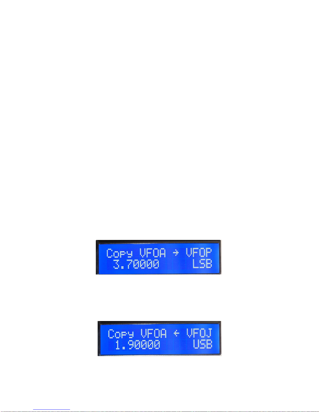
To copy the VFO-A frequency to VFO-B, select VFO A, and press and hold the VFO button
until you hear a long beep, and the display will show:
5

To copy the VFO-B frequency to VFO-A, first select VFO-B, and press and hold the button,
and a similar display will be shown except that the source will be VFOB, and the destination
will be VFOA.
If the button is pressed and held whilst the Splt is displayed, this is the same as VFO-A to
VFO-B.
If the User Configuration setting is for from 3 to 26 memories, then these can be selected
sequentially by a brief press of the button, or if the button is held, they can be selected by
rotating the VFO tuning knob. The last frequency/mode used for the selected VFO will be set.
Any frequency in the range 0 – 30MHz can be stored in the 26 VFO memories.
FILTER
This button is primarily used to select the receiver bandwidths, but also has a secondary
function of storing user frequencies.
A brief press of the button will cycle you through the Wide, Medium, and Narrow filter
bandwidths. The actual bandwidths employed are adjustable via the User Configuration
Menu.
A long press of the button will store the currently displayed frequency and mode into the user
band memory. There are 9 such memories, one for each amateur band, and they are selected
by the Rapid Band Switch feature assigned as a secondary function of the RIT button.
To use this feature, the User Configuration Band Switch setting has to be set to the User
mode. In this mode, the current frequency can be stored. Note, only frequencies within a
recognised amateur band can be stored. If an attempt is made to store an invalid frequency the
top line of the display will show:
Out Of Band!
Split Mode Copy, VFOA to VFOB
Saving A Frequency To A User Band
6

Similarly, if the Band Switch setting is in the Default mode, then the display will show:
Not In User Mode
If the Band Switch setting is in the Locked mode, then the display will show:
User Mem Locked!
A successful storage operation will display the message:
Saved to: nnn
where nnn will be replaced by a band from 160 – 10.
In this manner it is possible for the user to preset favourite frequencies for each amateur band,
and to retrieve them on demand. By selecting the Locked mode, these frequencies can be
protected.
System Calibration & Setup
It is assumed that the initial adjustments and settings have been made.
To enter the System Calibration & Setup menu, turn the transceiver off, and then press and
hold the power button until the message:
JUMA-TRX2 v1.07m
Service Mode
is displayed. To cycle through the various setting screens, briefly press the DISPLAY button.
Set Reference Oscillator Frequency
Default: 180000000Hz
The DDS is fed with the output of the precision crystal oscillator, and in the current models is
a packaged component with an output frequency of nominally 30MHz. The worst-case
tolerance for this oscillator is ±100ppm, which translates to a possible error of ±3kHz at
30MHz, and since this oscillator’s frequency is internally multiplied by 6 in the DDS chip,
this can be as high as ±18kHz at 180MHz.
To correct this, the reference frequency can be set to the frequency resulting from a x6
multiplication of the crystal oscillator’s actual output frequency.
In order to determine the necessary calibration factor, an accurate frequency counter is
essential. If you have access to a counter which has an accuracy of better than at least ±1ppm,
then measure the output frequency of the oscillator using the 10 second timebase, making at
least 10 measurements. Average the results to 2 decimal places and multiply by 6. Round this
figure to 1Hz, and this is the frequency to which the reference oscillator should be adjusted.
7

It is also possible to use a less accurate frequency counter if you can tune to a standard
frequency transmission. These are usually maintained to an accuracy of better than 0.1ppm.
For an example of how to use this method, please refer to Annex B.
The range of the input setting is checked, and there is an adjustment range of ±20kHz.
Anything outside of this figure is cause for extreme suspicion regarding the crystal oscillator.
Even adjustment settings of more than ±10kHz would warrant further investigation as the
vast majority of these oscillators have a basic frequency accuracy at room temperature of well
within the stated worst-case figure.
Supply Voltage Calibration Factor
Default: 5300
The microprocessor chip uses an internal 12-bit A-D convertor, and this in turn is referenced
to the +5V logic supply. Assuming that the regulator chip is exactly at +5V, this gives an
incremental digital step size 5mV. This is the basic resolution of the digital meter. Use an
accurate digital multimeter and measure the supply voltage at the transceiver’s input, and
adjust the calibration factor to achieve a display as close as possible to that measured.
The accuracy of the internal measurement system has been enhanced with this version of the
firmware, and the incremental quantisation steps are now such that it should be possible to set
the voltmeter to exactly match your measured value
The range is checked, and values from 4000 – 6000 are acceptable, although values
significantly different (more than ±250) from the default value suggest that the logic voltage
should be checked, and investigated.
RF Amplifier Drain Current
Default: 2400
Using an accurate ammeter, measure the current drawn by the amplifier when supplying 10W
in the Tune mode to a dummy load. The value is usually in the range of approximately 2.0 to
2.5A Note that the ammeter only measures the amplifier’s drain current. Using an accurate
ammeter measure the current drawn in the receive mode, and subtract this value from the total
current drawn in the transmit mode. Adjust the calibration factor to achieve the closest match.
The default value is usually satisfactory. The limits are from 1200 – 3600.
Forward Power Calibration Factor
Default: 3550
Using a dummy load, and an accurate power meter, set the transmitter’s output in the Tune
mode using the CARR control on the main board to a forward power of 10W. Adjust the
calibration factor to achieve the closest match. The limits are from 1500 – 5000.
S-Meter Calibration Factor
Default: 1920
This adjusts the accuracy of the S-Meter display, and requires careful consideration. Early
transceivers had a JFET type SST112 used for the AGC amplifier in position TR4 of the
variable gain amplifier A4-B on the main board. Later transceivers had a substitute device
8

type PMBFJ112, and the threshold voltage of this transistor differs from that of the SST112.
This leads to a significant difference in the two calibration settings.
In both cases, the adjustment procedure involves terminating the receiver in a 50Ωdummy
load, rotating R53 fully anticlockwise to achieve maximum gain, and then carefully rotating
clockwise until the audio noise just starts to decrease. This is the AGC threshold.
Using a signal generator inject an S9+40dB signal, 5mV, !33dBm, and adjusting the
calibration factor until either the numeric S-Meter just indicates S9+40dB, or the graphical S-
Meter just fills the horizontal display. Then lower the signal to S9, 50µV, !73dBm and by a
combination of R53 and the calibration factor adjustments try and achieve the best
compromise between full-scale and S9 for the two signal levels.
Since the threshold voltage of the two transistors is significantly different, early transceivers
are likely to have calibration factors close to the default, whilst later units will be in the range
of about 3,500 – 4,000. The limits are from 1,000 – 7,000.
Beep Time
Default: 50mS
This adjustment determines the time of all the audio annunciator signals. Adjust the value to
your preference. The range is checked, and values from 0 – 100mS are allowed. If the value is
set to 0, no audible annunciation will occur.
High SWR Trip Limit
Default: 3.00
This is a new feature as part of the alarm sub-system. If the SWR exceeds the trip limit, an
alarm will be generated and displayed on the main screen. The limit can be set from 1.00 –
5.00. Although a setting of 1.00 may seem odd, it allows you to check that the alarm is
working. Set the limit to 1.00, and exit from the System Calibration menu by saving the
settings.
Connect the transceiver to a dummy load, select Tune, and press the PTT switch. If the alarm
is working, then you should see a blinking message “HIGH SWR” on the top line of the display,
along with a beep. To cancel the alarm, release the PTT switch, and briefly press the PWR
button.
Switch off, and reselect the System Calibration menu again, and reset the SWR Trip to a
suitable value.
Overcurrent Trip
Default: ON
This allows you to enable or disable this alarm. If the alarm is disabled, then the following
page will be skipped, although its settings will be retained, and can be adjusted if the alarm is
enabled.
9

Overcurrent Trip (Adjustment)
Default: 2.5A
This is a new feature. Adjust the limit to a suitable value. The default is usually satisfactory.
The value can be set from 1.5A – 3.0A. Temporarily setting the trip to 1.5A allows you to
verify that it is working.
As with the SWR test, save the calibration settings, using a dummy load and the Tune mode,
press the PTT switch. The top line of the display will show the blinking message
“OVERCURRENT”, there will be a beep. Release the PTT switch and briefly press the PWR
button to cancel the alarm. Switch off and reselect the System Calibration menu and reset the
trip to a suitable value.
Note that the current measured is that of the final amplifier. The internal fuse is rated at 3.5A,
and since the transceiver’s logic and display sections can consume up to 400mA, the normal
trip limit of 2.5A represents a conservative safety margin. Under some circumstances,
especially if you are attempting to obtain the maximum power out of the transceiver, then it
may be necessary to set the limit to the maximum permissible, 3.0A. Be aware however that
with the logic and backlighting current as well, this is running very close to the fuse rating.
Overvoltage Trip
Default: ON
This allows you to enable or disable this alarm. If the alarm is disabled, then the following
page will be skipped, although its settings will be retained, and can be adjusted if the alarm is
enabled.
Overvoltage Trip (Adjust)
Default: 14.5V
This is a new feature. Adjust the limit to your preference. The range is from 14.0V – 15.0V.
Undervoltage Trip
Default: ON
This allows you to enable or disable this alarm. If the alarm is disabled, then the following
page will be skipped, although its settings will be retained, and can be adjusted if the alarm is
enabled.
Undervoltage Trip (Adjust)
Default: 11.0V
This is a new feature. Whilst the transceiver will continue to operate down to quite low
voltages, when operating portable from Gell cells most manufacturers recommend
terminating the discharge when the terminal voltage falls to 10.5V.
The transceiver can be set to warn you with a blinking “UNDERVOLTAGE” display and a beep at
any voltage from 10.50V – 11.50V. Note, in addition to this final warning, there is a pre-limit
warning which occurs at a voltage 100mV higher than this setting. This will display the
blinking alarm message: “Low Batt Voltage”, and beep.
10

Acknowledge and cancel the warning by briefly pressing the PWR button. This warning will
only be given once – it will NOT repeat! Once you have acknowledged the warning it
disappears. The only way to reset it is to power the transceiver off and back on again.
The next screen displays the message:
Push FAST long =
factory defaults
Only in this screen can you reset the transceiver to these default values. Push and hold the
FAST button until you hear a long beep, and the values will have been reset.
Otherwise, press the DISPLAY button briefly to return you to the initial screen, and briefly
press the FAST button to save the current values.
To abort the whole process, press and hold the PWR button to turn the transceiver off.
User Configuration Settings
To enter the User Configuration settings, press and hold the DISPLAY button until you hear a
long beep.
With version 1.07, there are now 21 settings that can be adjusted to your preferences. With
this many configurable settings there is now an additional feature allowing you to rapidly
access any configuration page.
To use this feature, press and hold the MODE button until you hear a long beep. Rotate the
VFO knob to select the desired configuration page. To adjust the setting, release the MODE
button, and use the VFO knob to adjust the current setting.
AGC Speed
Default: Slow
Use the tuning knob to select either Fast or Slow AGC action.
Low-Pass Filter Cut-Off Frequencies
Default: Wide – 2,500Hz, Mid – 2,205Hz Narrow – 1,000Hz
Use the FILTER button to select the filter whose cut-off frequency you wish to adjust. Use
the tuning knob to select the desired cut-off frequency. Note that the frequency resolution is
relatively coarse due to the methods used to clock the SCAF filter, but this is of little
consequence, since precise cut-off frequencies are not required.
Noise Blanker Option
Default: OFF
This is set to ON/OFF with the tuning knob. If no accessory board is installed, it should be set
to OFF.
11

Speech Processor
Default: OFF
The transceiver is equipped with a simple speech processor which uses a soft-clipping
method to achieve a higher peak to average ratio for speech to increase the average talk-
power.
However, this also leads to a certain amount of distortion, and thus this setting has to be
carefully related to the transmit SSB gain setting, R26. Too little gain, and no compression
will occur, too high a gain, and excessive distortion will occur. Turn the Speech Processor on,
and listen on another receiver when operating into a dummy load to determine the optimum
gain setting.
Audio Input Source
Default: Mic
Use the tuning knob to select microphone or line. When set to line, the gain is reduced by
about 30dB. This allows the connection of the transceiver to the output of a computer’s audio
system for digital mode operation.
Note however that to satisfactorily use digital modes the speech processor must be turned off,
and the transceiver’s microphone amplifier circuit slightly modified to completely disable the
speech processor in the off mode.
Keyer Mode Selection
Default: Iambic B
Select Iambic A, Iambic B, Dot Priority, or Straight key operation.
CW Pitch
Default: 700Hz
Use the tuning knob to select the desired pitch for CW signals. The range is checked and
values from 300Hz – 1,100Hz are acceptable. This is also the offset used when transmitting.
The actual transmit frequency is lower than the receive carrier by this amount.
CW Pot Mode
Deafult: CW Speed
The CW pot can be used either as a keyer speed setting or a receiver squelch control. Use the
tuning knob to select the desired function.
LCD Backlight
Default: 350
The intensity of the LCD display can be adjusted with this setting. Values from 0 – 1,100 are
accepted.
LCD Contrast
Default: 2000
This setting adjusts the display contrast. The default of 2,000 is usually acceptable. The range
of values accepted is from 0 – 3,500.
12

LCD Timer
Default: OFF
The display can be automatically turned off after a preset time using this feature. Adjust the
timer to a value between OFF and 3,600 seconds.
RS-232
Default: Yaesu CAT
This setting governs a number of peripheral features. It can be set to the following modes:
JUMA TRX2
This mode is used to enable serial communication with the companion JUMA PA100D
100W linear amplifier.
Yaesu CAT
This allows communication with PC logging programs, and emulates a Yaesu transceiver. For
a list of commands that are emulated, please see Annex C.
Kenwood CAT
This allows communication with PC logging programs, and emulates a Kenwood TS-480
transceiver. For a list of commands that are emulated, please see Annex D.
Voice Memory
This mode is used with the accessory voice memory board.
Test
This mode is used to verify the integrity of the transceiver’s internal circuitry and software, as
well as check that the serial communications port is working correctly. In this version of the
firmware several serial port bugs were corrected, and a user help feature added which briefly
describes the operation of each command.
Connect the transceiver to a PC, use a suitable terminal program, ensure that the speed
settings are correct. Send the letter I, ?, H, or h from the PC and the transceiver should
respond with a screen of information. The actual usage of these commands in beyond the
scope of this document, and in any case is only likely to be of interest to those wishing to
customise the software.
Note that these commands are not in any way destructive – they cannot permanently affect the
overall operation of the transceiver. For a brief description please see Annex E.
Baud Rate
Default: 9600
This allows setting the speed of the serial port from 1,200 – 115,200 Baud. The default of
9,600 is usually satisfactory.
13

VFO Memory Operation
Default: A/B + Split
This setting governs how the various VFO memories are used and organised. The settings
range from A/B + Split mode, to 3 – 26 memories.
Split mode operation involves transmitting on one frequency, and receiving on another. The
frequencies can be anywhere in the tuning range of the transceiver. VFO A is used for the
receive frequency; VFO B for transmit.
When not using Split mode, you can select the number of VFO memories available to you
from 3 – 26, which will be indicated on the display by the letters VFOA – VFOZ. The current
displayed frequency and mode is automatically stored in the selected VFO.
These VFOs can be selected by a brief press of the VFO button, or the VFO button can be
held down and the memories selected by the tuning knob.
S-Meter
Default: Graphic
This new feature allows you to select either a graphical S-Meter (Original) or a numeric S-
Meter. The gain characteristics of a correctly adjusted and calibrated receiver are almost
exactly logarithmic over the dynamic range of the receiver, which lends itself to an easy
implementation of either display with reasonable accuracy. Use the tuning knob to select
either type of display.
TX Disable
Default: ON
This is a new feature. The original firmware allowed transmission on any frequency,
including those outside the amateur bands. This meant one had to pay careful attention when
operating close to the band edges in order to avoid an infraction of your licence conditions.
By enabling this feature, if you attempt to transmit in any mode on a frequency outside the
recognised band, the transmitter is inhibited, and the display will show a message:
Out Of Band!
In addition, in the receive mode, there is a small annunciator displayed immediately between
the frequency display and the VFO selection/mode section of the lower line of the screen if
the current receive frequency is outside the amateur bands.
Transmit Inhibit
14

Even if this feature is turned off, the receive annunciator is still displayed, and storage of a
frequency in the User Band memory is inhibited.
Auto Sideband Select
Default: ON
This is a new feature. Conventionally, for frequencies above 10MHz USB is the preferred
mode for voice communication, conversely, LSB for frequencies lower than 10MHz. This
feature will automatically select the correct sideband when tuning to an amateur band using
the Rapid Bandswitch Feature. It does not affect tuning when using the tuning knob. Even
with auto sideband selected, you may still choose any operating mode on any band.
Frequency Display Selection
Default: Fixed B
This is a new feature. The original frequency display was limited to 10Hz resolution, and
used two decimal points, between the MHz and 100kHz digits and between the kHz and
100Hz digits. This feature now permits a variety of display options.
Original
The frequency will be displayed as:
New
The frequency will be displayed depending upon the tuning rate being used, thus:
Original Frequency Display
Slow Tuning Rate – 1Hz
Medium Tuning Rate – 10Hz
15

Note that the precision is not affected, the display is merely rounded to the appropriate tuning
rate’s resolution, but selecting a higher resolution tuning rate will reveal the rounded digits.
With version 1.07g and later, the accuracy of the synthesiser has been improved. See
Annex A for a full explanation.
Fixed A
The display is fixed at 1Hz resolution independent of the tuning rate used. For frequencies
below 1MHz the decimal point will move to the kHz position, and no leading zeros are used.
(See note 6 at the end of this document.)
Fixed B
The display is fixed at 10Hz resolution, independent of the tuning rate used.
Fast Tuning Rate – 100Hz
Very Fast Tuning Rate – 10kHz
Fixed Resolution – 1Hz
Fixed Resolution – 10Hz
16

Band S/W
Default: Default
This is a new feature. This setting governs how the Rapid Bandswitch feature operates.
Default
In this mode, when selecting an amateur band, the frequency used will be fixed at the band’s
centre.
BAND FREQUENCY MHz
160 metres 1.900
80 metres 3.650
40 metres 7.100
30 metres 10.125
20 metres 14.175
17 metres 18.118
15 metres 21.225
12 metres 24.940
10 metres 28.850
User
In this mode, initially when the firmware is first loaded the frequencies are set to match the
default settings. However, the user can store new frequencies as desired, provided that they
are within the amateur band in question. The upper and lower frequencies to be used as the
band edges are determined by the setting of the Band Limits parameter in a following menu.
The out-of-band indication is dependent upon the mode in use. For USB, the carrier
frequency has the transmit filter bandwidth of 2.6kHz added to ensure that the entire upper
sideband falls within the upper band edge, no correction is applied to the lower band edge.
For LSB, the frequency has the transmit filter bandwidth subtracted to ensure that the entire
lower sideband falls within the lower band edge. Similarly for CW, where in this case the CW
Pitch is used.
For the Tune mode, no corrections are applied, as the carrier frequency itself is used.
Locked
This mode uses the currently preset User frequencies, but the memory is locked so that no
alteration can occur.
17

Include RIT
Default: NO
This is a new feature. If this is turned on, then the RIT offset frequency will be used to modify
the frequency displayed to show the actual receive frequency.
Band Limits
Default: IARU
This is a new feature. The transceiver’s band edge frequencies can be set to either the IARU
Region 1 limits, or the USA limits. When altering this setting note that it will take effect
when the transceiver is next powered up.
Minor Enhancements
1. The RIT, VFO, and FAST/VFAST buttons are locked out when in the User Setup
mode. The MODE button is used to rapidly access the configuration pages. Note that
although the MODE button is active in the User Setup mode, no mode changes will
occur, that is, the existing mode (LSB/USB/CW/Tune) will not be disturbed.
2. The MODE, FILTER, RIT, VFO, and FAST/VFAST buttons are locked out when in
the transmit mode.
3. The power-down sequence timing is no longer critical. In the previous software, one
had to time the release of the power button fairly accurately to avoid either aborting
the sequence or powering the transceiver back up. In this version, as soon as the
display blanks you can release the button, holding it down will no longer cause a
power-up to occur.
4. Various audio glitches when changing frequencies or modes have been eliminated or
greatly suppressed, although there are still a few stubborn candidates left. Work in
progress.
5. The lowest frequency to which the transceiver can be tuned is 0Hz. Whilst the
frequencies below about 30kHz have no real importance, the very low frequency
output at audio frequencies does allow the user to verify that the DDS chip is
operating. By tuning down into the audio range you will hear an audio beat note which
can be measured with a frequency counter to provide an approximate indication that
the frequency synthesis is correct.
6. Version 1.07h and later slightly modified the way that the Fixed-A display operates.
After careful consideration, I decided that displaying frequencies below 1MHz with
leading zeros was simply ugly. The display now shows a decimal point at the MHz
position for frequencies above 999.999kHz, and simply moves the decimal point to
the kHz position and fills the leading spaces with blanks for frequencies from 1kHz to
999.999kHz. For frequencies below 1kHz, no decimal point is displayed.
7. The spurious power-down count when locking or unlocking the VFO has been
cleared.
18

8. The filter change points for the 2MHz and 4MHz filters have been moved up by
10kHz. It was particularly disconcerting that right at the 2.0MHz and 4.0MHz
frequencies these filters would be changed. The new frequencies are 2.010MHz, and
4.010MHz.
9. The Serial Test facility has been enhanced with the addition of a dump of the
attenuator settings corresponding to the various internal filters.
10. Various minor internal code optimisations.
Adrian Ryan – 5B4AIY
12 October 2011
19

Annex A
JUMA Frequency Step Accuracy
The Juma TRX2 using firmware revision 1.06 has an inherent frequency resolution of 10Hz.
This means that the actual frequency to which the transceiver is tuned is within ±5Hz of the
displayed frequency, if we neglect the reference oscillator errors. Or is it?
If we carefully examine the frequency display, we can observe some interesting quirks. Try
this, tune the transceiver to, say, 10.00000Mhz, and select the fast tuning rate of 100Hz, now
rapidly rotate the VFO knob to increase the frequency and carefully observe the least
significant (10Hz) digit. After a large number of steps the digit will suddenly change by 1.
Select the slow (10Hz) tuning rate and carefully go back and find the exact frequency at
which the 10Hz digit changed, and note it. As an example, in my case it was 10.20840MHz.
Now re-select the fast tuning rate and increase the frequency, and in my case at 10.46510 the
10Hz digit changed again and with a single increment from the tuning knob the display
changed from 10.46510 to 10.46519, and the next increment was to 10.46529.
The reason for this anomaly is not hard to find. The output frequency of the synthesiser is:
local oscillator
f = N * 180000000 / 2^33 Hz
Where N is the 32-bit binary word used to load the DDS chip. In fact, the actual output
frequency is twice this, but the synthesiser’s frequency is divided by two to obtain the phase-
quadrature local oscillator signal.
The frequency steps are obtained from an array of steps and for a step increment of 100Hz the
value is 4,772. This is the binary increment that is added to the existing frequency word for
every step generated by the VFO encoder at the 100Hz tuning rate.
The actual frequency increment is therefore:
increment
f = 4772 * 180000000 / 8589934592
= 99.996104837 Hz
There is thus an incremental step error of !0.003895164 Hz for each step, and eventually
these step errors accumulate until there is sufficient error for the next step to cause the 10Hz
digit to change.
In fact, after every 2,567 steps this anomaly will appear, corresponding to a frequency change
of about 256Khz.
Now, one could reasonably say, “So what?” and I would entirely agree that for all practical
purposes this is of no real significance, the actual frequency of the transceiver is always
within ±5Hz of the displayed frequency, which is more than adequate – even on the lowest
20
Popular Transceiver manuals by other brands

Kenwood
Kenwood NX-200 K2 Service manual

FlexRadio
FlexRadio FLEX-6400 installation instructions

Cobalt Digital Inc
Cobalt Digital Inc 9450GT Series product manual

Comtech EF Data
Comtech EF Data CSAT-5060 Installation and operation manual

Dallas Semiconductor
Dallas Semiconductor MAXIM DS21354 manual

Kramer
Kramer KDS-8 user manual