JUMO Ex-i User guide

70753000T99Z001K000
V1.00/EN/00770263/2022-05-13
JUMO Ex-i
Repeater power supply and
input isolating amplifier
Safety Manual


Contents
Contents
1 Introduction . . . . . . . . . . . . . . . . . . . . . . . . . . . . . . . . . . . . . . . . . . . . . . . . . 5
1.1 Safety information . . . . . . . . . . . . . . . . . . . . . . . . . . . . . . . . . . . . . . . . . . . . . . . . . . . . . . . . .5
1.2 Description . . . . . . . . . . . . . . . . . . . . . . . . . . . . . . . . . . . . . . . . . . . . . . . . . . . . . . . . . . . . . .6
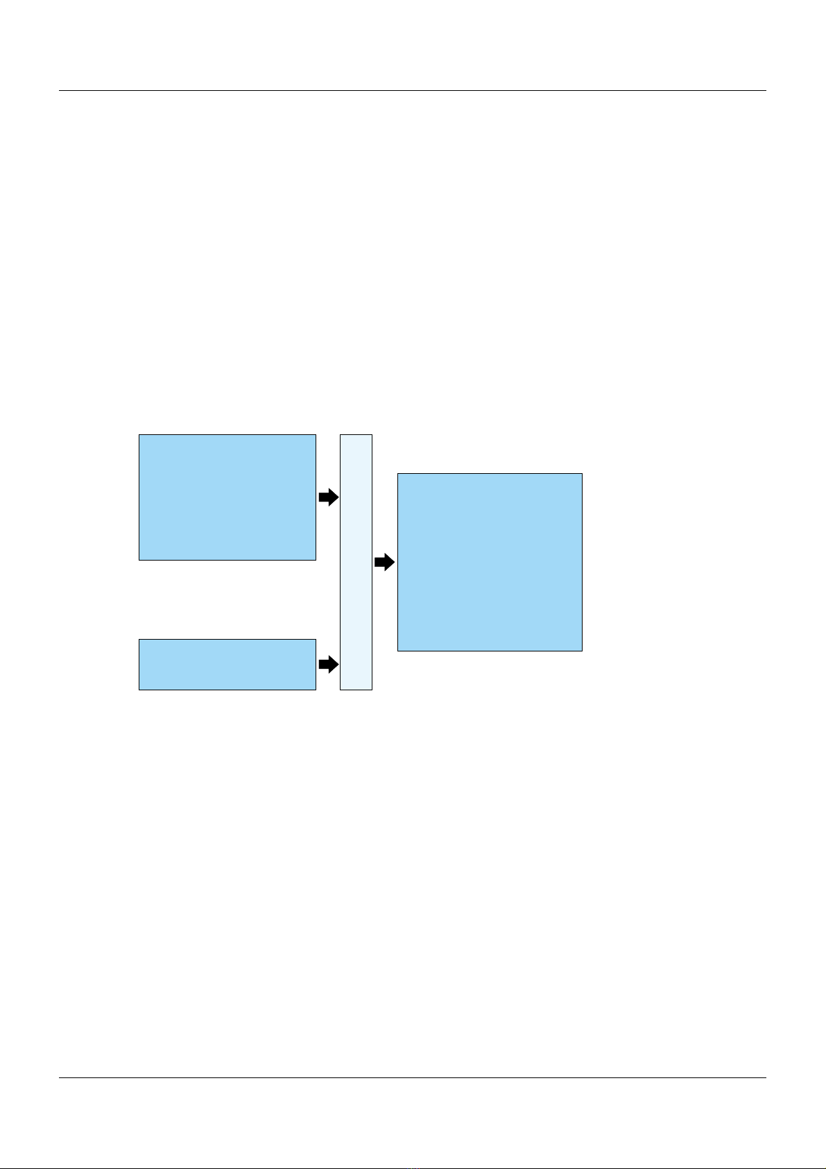
1.3 Block diagram . . . . . . . . . . . . . . . . . . . . . . . . . . . . . . . . . . . . . . . . . . . . . . . . . . . . . . . . . . . .6
2 Safety requirements and installation instructions. . . . . . . . . . . . . . . . . . 7
2.1 Installation instructions . . . . . . . . . . . . . . . . . . . . . . . . . . . . . . . . . . . . . . . . . . . . . . . . . . . . .7
2.2 Intrinsic safety . . . . . . . . . . . . . . . . . . . . . . . . . . . . . . . . . . . . . . . . . . . . . . . . . . . . . . . . . . . .7
2.3 Installation in zone 2 . . . . . . . . . . . . . . . . . . . . . . . . . . . . . . . . . . . . . . . . . . . . . . . . . . . . . . .8
2.4 Areas that are potentially explosive due to dust . . . . . . . . . . . . . . . . . . . . . . . . . . . . . . . . . .8
2.5 Safety-related applications (SIL). . . . . . . . . . . . . . . . . . . . . . . . . . . . . . . . . . . . . . . . . . . . . .8
2.6 Safety data according to ATEX . . . . . . . . . . . . . . . . . . . . . . . . . . . . . . . . . . . . . . . . . . . . . . .9
2.7 UL note . . . . . . . . . . . . . . . . . . . . . . . . . . . . . . . . . . . . . . . . . . . . . . . . . . . . . . . . . . . . . . . . .9
3 Installation . . . . . . . . . . . . . . . . . . . . . . . . . . . . . . . . . . . . . . . . . . . . . . . . . . 11
3.1 Connection instructions. . . . . . . . . . . . . . . . . . . . . . . . . . . . . . . . . . . . . . . . . . . . . . . . . . . . .11
3.2 Electrostatic discharge . . . . . . . . . . . . . . . . . . . . . . . . . . . . . . . . . . . . . . . . . . . . . . . . . . . . .11
3.3 Design. . . . . . . . . . . . . . . . . . . . . . . . . . . . . . . . . . . . . . . . . . . . . . . . . . . . . . . . . . . . . . . . . .12
3.4 Schematic diagram . . . . . . . . . . . . . . . . . . . . . . . . . . . . . . . . . . . . . . . . . . . . . . . . . . . . . . . .13
3.5 Inputs (intrinsically safe) . . . . . . . . . . . . . . . . . . . . . . . . . . . . . . . . . . . . . . . . . . . . . . . . . . . .13
3.6 Output of current without HART communication. . . . . . . . . . . . . . . . . . . . . . . . . . . . . . . . . .13
3.7 Output of current with HART communication . . . . . . . . . . . . . . . . . . . . . . . . . . . . . . . . . . . .14
3.8 HART® communication . . . . . . . . . . . . . . . . . . . . . . . . . . . . . . . . . . . . . . . . . . . . . . . . . . . .14
3.9 Output Voltage . . . . . . . . . . . . . . . . . . . . . . . . . . . . . . . . . . . . . . . . . . . . . . . . . . . . . . . . . . .14
3.10 Voltage supply. . . . . . . . . . . . . . . . . . . . . . . . . . . . . . . . . . . . . . . . . . . . . . . . . . . . . . . . . . . .14
3.11 Dimensions . . . . . . . . . . . . . . . . . . . . . . . . . . . . . . . . . . . . . . . . . . . . . . . . . . . . . . . . . . . . . .14
3.12 Mounting . . . . . . . . . . . . . . . . . . . . . . . . . . . . . . . . . . . . . . . . . . . . . . . . . . . . . . . . . . . . . . . .15
3.13 Connecting the lines . . . . . . . . . . . . . . . . . . . . . . . . . . . . . . . . . . . . . . . . . . . . . . . . . . . . . . .15
3.14 Startup . . . . . . . . . . . . . . . . . . . . . . . . . . . . . . . . . . . . . . . . . . . . . . . . . . . . . . . . . . . . . . . . .15
3.15 Level conversion . . . . . . . . . . . . . . . . . . . . . . . . . . . . . . . . . . . . . . . . . . . . . . . . . . . . . . . . . .16
4 Comparison of the safety data. . . . . . . . . . . . . . . . . . . . . . . . . . . . . . . . . . 17
5 Safety-related applications. . . . . . . . . . . . . . . . . . . . . . . . . . . . . . . . . . . . . 19
5.1 Safety function and safety requirements. . . . . . . . . . . . . . . . . . . . . . . . . . . . . . . . . . . . . . . .19
5.2 1-channel operation as a repeater power supply and input isolating amplifier for SIL2 (1oo1)
applications 19
5.2.1 Safety/integrity requirements . . . . . . . . . . . . . . . . . . . . . . . . . . . . . . . . . . . . . . . . . . . . . . . .19
5.3 2-channel operation as a repeater power supply and input isolating amplifier for SIL3 (1oo2)
applications 20
5.3.1 Safety/integrity requirements . . . . . . . . . . . . . . . . . . . . . . . . . . . . . . . . . . . . . . . . . . . . . . . .20
5.4 Conditions . . . . . . . . . . . . . . . . . . . . . . . . . . . . . . . . . . . . . . . . . . . . . . . . . . . . . . . . . . . . . . .21
5.5 Installation and startup . . . . . . . . . . . . . . . . . . . . . . . . . . . . . . . . . . . . . . . . . . . . . . . . . . . . .22

Contents
5.6 Notes for operation . . . . . . . . . . . . . . . . . . . . . . . . . . . . . . . . . . . . . . . . . . . . . . . . . . . . . . . .22
5.7 Regular tests. . . . . . . . . . . . . . . . . . . . . . . . . . . . . . . . . . . . . . . . . . . . . . . . . . . . . . . . . . . . .23
5.8 Repairs . . . . . . . . . . . . . . . . . . . . . . . . . . . . . . . . . . . . . . . . . . . . . . . . . . . . . . . . . . . . . . . . .23
5.9 Standards . . . . . . . . . . . . . . . . . . . . . . . . . . . . . . . . . . . . . . . . . . . . . . . . . . . . . . . . . . . . . . .24
5.10 Abbreviations . . . . . . . . . . . . . . . . . . . . . . . . . . . . . . . . . . . . . . . . . . . . . . . . . . . . . . . . . . . .24

5
1 Introduction
1 Introduction
1.1 Safety information
General
This manual contains information that must be observed in the interest of your own safety and to avoid
material damage. This information is supported by symbols which are used in this manual as indicated.
Please read this manual before starting up the device. Store this manual in a place that is accessible to
all users at all times.
If difficulties occur during startup, please do not intervene in any way that could jeopardize your warranty
rights!
Warning symbols
WARNING!
This symbol in connection with the signal word indicates that personal injury may occur if the respective
precautionary measures are not carried out.
CAUTION!
This symbol indicates that components could be destroyed by electrostatic discharge (ESD = Electro
Static Discharge) if the respective cautionary measures are not taken.
Only use the ESD packages intended for this purpose to return device inserts, assembly groups, or as-
sembly components.
NOTICE!
This note in connection with the signal word indicates that material damage or data loss will occur if
the respective precautionary measures are not taken.
Note symbols
NOTE!
This symbol refers to important information about the product, its handling, or additional benefits.
REFERENCE!
This symbol refers to additional information in other sections, chapters, or other manuals.

1 Introduction
6
1.2 Description
The JUMO Ex-i power supply/input isolating amplifier 707530 is designed for operating intrinsically safe
transmitters (Ex-i) and mA current sources installed in potentially explosive (Ex) areas. The connected
2-wire transmitters are supplied with energy and analog 0/4 to 20 mA measured values are transmitted
from the potentially explosive area to the non-explosive area.
The external connection defines whether the device operates in supply isolating amplifier mode or iso-
lating amplifier mode. The output of the module can be operated in active or passive mode. Digital
(HART) communication signals can be superimposed over the analog measured value on the Ex or non
Ex side and transmitted bidirectional.
To increase the HART impedance in low-resistance systems an additional resistor can be activated in
the output circuit using the switch on the device's front. The device provides a 3-way electrical isolation
and the energy supply is designed as wide range power supply (24 to 230 V).
SIL measuring chains up to SIL2 and, in the event of a 2-channel setup, up to SIL3, are possible with
the Ex-i repeater power supply and input isolating amplifier.
1.3 Block diagram
Output signal voltage
0 to 5 V
1 to 5 V
Output signal current (active)
0 to 20 mA
4 to 20 mA
Output signal current (passive)
0 to 20 mA
4 to 20 mA
Voltage supply
AC/DC to24 230 V
-20 +10 %, 50 60 Hzto to
Measuring input
Current
0 to 20 mA
4 to 20 mA
Transmitter voltage supply
> 16 V at 20 mA
> 15.3 V at 22.5 mA
Ex-i Supply/Input Isolating AmplifierPower

7
2 Safety requirements and installation instructions
2 Safety requirements andi nstallation instructions
2.1 Installation instructions
2.2 Intrinsic safety
– The device is associated equipment with an EPL [Ga], [Da] (category 1) of the ignition protection
type "intrinsic safety" and can be installed as a device with the EPL Gc (category 3) in the potentially
explosive area of Zone 2. The intrinsically safe electrical circuits can be routed up to Zone 0 /
Zone 20. It meets the requirements from the following standards.
EN 60079-0, EN 60079-11, EN 60079-15
For detailed information, please refer to the declarations of conformity.
– The installation, operation, and maintenance must be carried out by personnel with electrotechnical
qualifications. Follow the described installation instructions.
– Adhere to the applicable conditions and safety regulations (including national safety regulations)
and the general rules of engineering during set-up and operation.
– Observe the safety information, conditions, and limits of use specified in the product documentation.
Comply with them.
– Opening or modifying the device is not admissible. Do not repair the device yourself; instead, you
should replace it with an equivalent device. Repairs must only be performed by the manufacturer.
The manufacturer is not liable for damage resulting from violations of this.
– The protection type IP20 (IEC/EN 60529) of the device is intended for a clean and dry environment.
Do not expose the device to any mechanical and/or thermal stresses that exceed the described lim-
its.
– Only use the device up to a pollution degree of 2 according to IEC 60664-1.
– The connected, non-intrinsically safe electrical circuits must have a maximum overvoltage
category II according to IEC 60664-1.
– The device must be taken out of operation if it is damaged, has been improperly stressed or stored,
or malfunctions.
– The device complies with the EMC regulations for industrial areas (EMC class A). It may cause EMC
problems if used in residential areas.
– The products must be installed according to all relevant standards for electrical systems in poten-
tially explosive areas.
– Only use copper cables as connecting cables.
– The device is approved for intrinsically safe (Ex i) electrical circuits up to Zone 0 (gas) and Zone 20
(dust) of the Ex area. The safety technology values for intrinsically safe equipment and the connect-
ing lines must be observed for the hook-up process (EN 60079-14) and the values specified in this
installation note and/or the EU examination certificate must be observed.
– During measurements on the intrinsically safe side, make sure to observe the valid conditions rele-
vant to the interconnection of intrinsically safe equipment. Only use the approved measuring devic-
es in intrinsically safe electrical circuits.
– If the device has been used in non-intrinsically safe electrical circuits, using it again in intrinsically
safe electrical circuits is prohibited! Clearly mark the device as not intrinsically safe.

2 Safety requirements and installation instructions
8
2.3 Installation in zone 2
2.4 Areas that are potentially explosive due to dust
2.5 Safety-related applications (SIL)
When using the device in safety-related applications, observe the instructions in the chapter "Safety-re-
lated applications", as the requirements for the safety-related function vary.
chapter 5 "Safety-related applications", Page 19
– Adhere to the specified conditions for use in potentially explosive areas. Install the device in a suit-
able approved housing with at least IP54 protection that meets the requirements of EN 60079-15,
Section 1.
Also observe the requirements of EN 60079-14.
– In potentially explosive areas, connecting and disconnecting cables and connectors in non-intrinsi-
cally safe electrical circuits or actuating DIP switches is only permitted in a de-energized state or if
no potentially explosive atmosphere is present.
– The device must be taken out of operation and removed from the Ex area immediately if it is dam-
aged, has been improperly stressed or stored, or malfunctions.
– Temporary malfunctions (transients) must not exceed the value 497 V (355 V x 1.4).
– The device is not designed for installation in Zone 22.
– If you nevertheless want to use the device in Zone 22, you have to install it in a housing according
to EN 60079-31. In doing so, observe the maximum surface temperatures. Adhere to the require-
ments of EN 60079-14.
– Only carry out interconnection with the intrinsically safe electrical circuit in areas that are potentially
explosive due to dust (Zones 20, 21, or 22) if the equipment connected to this electrical circuit is
approved for this zone (e.g. category 1D, 2D, or 3D).

9
2 Safety requirements and installation instructions
2.6 Safety data according to ATEX
Repeater power supply amplifier operation
Input isolating amplifier operation
2.7 UL note
The safety requirements resulting from the UL approval are included in the "Control Drawing". The "Con-
trol Drawing" is part of the package leaflet.
Max. output voltage Uo25.2 V
Max. output current Io93 mA
Max. output power Po587 mW
Max. external inductance Lo,
max. external capacitance Co
Simple electrical circuit IIB: 4 mH/820 nF
Simple electrical circuit IIC: 2 mH/107 nF
Safety-related maximum voltage
Um
Supply terminals AC/DC 253 V
Output terminals AC 253 V, DC 125 V
Max. voltage Ui≤30 V
Max. current Ii≤150 mA
Max. internal inductance LiNegligible
Max. internal capacitance CiNegligible
Safety-related maximum voltage
Um:
Supply terminals AC/DC 253 V
Output terminals AC 253 V

2 Safety requirements and installation instructions
10

11
3 Installation
3
Installation
3.1 Connection instructions
WARNING!
Electrical dangers due to improper installation
Observe the following connection information to ensure safe installation according to EN/UL 61010-1:
WARNING!
Explosion hazard
If you have used the device in non-intrinsically safe electrical circuits, you can then no longer use it in
intrinsically safe electrical circuits. Clearly mark the device as not intrinsically safe.
3.2 Electrostatic discharge
CAUTION!
Electrostatic discharge!
The device contains elements that may be damaged or destroyed by electrostatic discharge. When deal-
ing with the device, observe the necessary safety measures against electrostatic discharge (ESD) ac-
cording to EN 61340-5-1 and IEC 61340-5-1.
– In the device installation, separating devices and auxiliary flow circuit protection devices must be
provided with suitable AC or DC values.
– The device is intended for installation in a control cabinet or in a comparable housing. The device
must only be operated when installed. The control cabinet must correspond to the requirements of
a fire protection housing of the safety standard UL/IEC 61010-1 and provide adequate protection
against electric shock or burns.
– Provide a switch/power switch close to a device that is marked as the disconnecting device for this
device (or the entire control cabinet).
–Provideanovercurrent protection device (I ≤16 A) in the installation.
– Install the device in an appropriate housing with a suitable protection type according to IEC/EN
60529 in order to protect against mechanical or electrical damage.
– Disconnect the device from all effective energy sources if it is not a SELV or PELV electric circuit
when carrying out repair or maintenance work.
– If the device is not used according to the documentation, the intended protection may be impaired.
– Settings must only be made on the device using the DIP switch when it is in a de-energized state.
– The device has basic insulation of 300 Veff to adjacent devices due to its housing. Note this when
installing multiple devices next to one another and install additional insulation if necessary. If the ad-
jacent device has basic insulation, no additional insulation is required.
– The voltages present at the input, output, and supply are extra-low voltages (ELV). The switching
voltage at the relay output may be a voltage that is dangerous to the touch (> AC 30 V / > DC 60 V)
depending on the application. In this case, safe, galvanic isolation to the other connections must be
available.

3 Installation
12
3.3 Design
(1) Pluggable screw connection terminal block with integrated test socket
(2) DIP switch (S1: toggling current/voltage output; S2: resistance in the output circuit to increase
HART impedance)
(3) Green LED: “PWR” voltage supply
(4) Snap-on foot for mounting rail installation
3.1 3.2 3.3
1.1 1.2 1.3
PWR
1.1 1.2
4.1 4.2
3.1 3.2
707530
Ex-i repeater power supply/
input isolating amplifier
1.3
4.3
3.3
I II
1
2
()1
(1)
(3)
(4) (2)

13
3 Installation
3.4 Schematic diagram
3.5 Inputs (intrinsically safe)
• Repeater power supply operation (feeding input for 2-conductor transmitter or 2-conductor measur-
ing transducer) on terminal 4.1 (+) and 4.2 (-)
• Input isolating amplifier operation (non-feeding input for four-wire transmitter/power sources) at ter-
minals 4.2 (+) and 4.3 (-)
3.6 Output of current without HART communication
Zone 2
Div. 2
IN OUT
24...230 V
AC/DC
4.3
4.2
3.3
3.2
250 Ω
4.1 3.1
1.2
1.1
250
Ω
S2
S1
–
~
PLC / DCS
passive
3.2
3.1 +
-
active
3.3
3.2 +
-
AI
Sensor/Field
or
+
-4.2
4.1
Zone 0,1,2
Zone 20,21,22
Div. 1,2
4.3
4.2
+
-
Connection for Terminals DIP-switch positiona
S1 S2
Source (passiv input card) 3.1 (+) and 3.2 (-) III
Sink (active input card) 3.2 (+) and 3.3 (-) III
aThe two DIP-switches are located at the front of the device. Settings made to the device with DIP-switches must
occur in a voltage-free state.

3 Installation
14
3.7 Output of current with HART communication
3.8 HART® communication
HART communicators (HHT) can be connected as shown in the basic circuit diagram. Test sockets (di-
ameter 2.3 mm) are integrated in the screw connection terminal blocks for this purpose.
3.9 Output Voltage
3.10 Voltage supply
The voltage supply is fed in via the connection terminals 1.1 (+) und 1.2 (-) (DC/AC 24 to 230 V).
3.11 Dimensions
Connection for Electrical
circuit im-
pedance
Connection DIP-switch positiona
of the input card
at terminal
of the HART
communicator
S1 S2
Source (passiv input card) 250 3.1 (+) and 3.2 (-) 3.1 and 3.2 III
250 3.1 (+) and 3.2 (-) 3.2 and 3.3 I I
Sink (active input card) 250 3.2 (+) and 3.3 (-) 3.2 and 3.3 III
250 3.2 (+) and 3.3 (-) - I II
aThe two DIP-switches are located at the front of the device. Settings made to the device with DIP-switches must
occur in a voltage-free state.
Connection for Connection of the input card at the terminal DIP-switch positiona
S1 S2
Source – passive input card 3.1 (+) and 3.2 (-) II II
aThe two DIP-switches are located at the front of the device. Settings made to the device with DIP-switches must
occur in a voltage-free state.
114 5.
99
112 5.
17 5.

15
3 Installation
3.12 Mounting
1. Mount the module on a 35 mm mounting rail according to EN 60715.
2. Install the module in a suitable housing in order to meet the requirements for the protection rating.
3.13 Connecting the lines
Screw connection
Admissible conductor cross section: 0.2 mm2to 2.5 mm2
1. Strip 7 mm of the wire and provide it with ferrules.
2. Insert the wire into the relevant connection terminal.
3. Tighten the screw in the opening above the connection terminal using a screwdriver.
Connection torque: 0.6 Nm
3.14 Startup
1. Before startup, check the device is working correctly and is wired properly, in particular the wiring
and identification marking of the intrinsically safe electrical circuits.

3 Installation
16
3.15 Level conversion
Level conversion between the input and output is not provided for.
4 to 20 mA input signals therefore become 4 to 20 mA output signals.
In the same manner, active input signals of 0 to 20 mA become galvanically isolated 0 to 20 mA output
signals.

17
4 Comparison of the safety data
WARNING!
Explosion hazard
Compare the safety data before you connect a module located in the Ex-i area to the JUMO Ex-i isolating
switch amplifier.
Provide proof of intrinsic safety according to standard EN 60079-14 and other national standards and
installation specifications, if applicable.
Safety data of the
You can find the values for Uo, Io, Po, Lo, Coin chapter 2.6 "Safety data according to ATEX", Page 9.
Example for proof of intrinsic safety (simple electrical circuit):
Lcand Ccdepend on the cables/lines used.
Proof of intrinsic safety (simple intrinsically safe electrical circuit)
In a simple intrinsically safe electrical circuit without external concentrated capacitances (Ci) and without
external concentrated inductances (Li), the full values of C0nd L0can be used.
chapter 2.6 "Safety data according to ATEX", Page 9
Proof of intrinsic safety (mixed intrinsically safe electrical circuit)
Condition for the mixed intrinsically safe electrical circuit with external concentrated capacitances (Ci)
and/or external concentrated inductances (Li):
•L
i<1%ofL
0 or Ci<1%ofC
0
The full values of C0and L0can also be used here.
chapter 2.6 "Safety data according to ATEX", Page 9
•L
i≥1%ofL
0and Ci≥1%ofC
0
The values of C0and L0that have been reduced by 50 % must be used here:
•C
i+ Cc≤0.5 C0
•L
i+ Lc≤0.5 L0
In order to be able to realize larger line lengths, you can also use certified value pairs alternatively to the
values reduced by 50 %.
chapter 2.6 "Safety data according to ATEX", Page 9
Field devices: Ui, Ii, Pi, Li, Ci
Ex-i repeater power supply and input isolating
amplifier:
Uo, Io, Po, Lo, Co
Data Conditions
Ui≥Uo-
Ii≥Io-
Pi≥Po-
Li+L
c≤LoLi<1%ofL
oor Ci<1%ofC
o
Ci+C
c≤Co
Li+L
c≤0.5 LoLi≥1%ofL
oor Ci≥1%ofC
o
Ci+C
c≤0.5 Co

4 Comparison of the safety data
18

19
5 Safety-related applications
The following information applies for the device:
The safety-oriented repeater power supply and input isolating amplifier mentioned above is certified for
compliance with DIN EN 61508 and IEC 62061.
Test certificate: ZP/C006/21
5.1 Safety function and safety requirements
The safety function of the device consists of galvanically isolated transmission of a standard signal of
4 to 20 mA with a max. deviation of 2 %.
Output values outside the range of 3.6 to 21 mA are considered a safe operating state, which is detected
by the downstream control system.
Safe faults in the device are therefore those where the device delivers an output signal that does not
deviate more than 2 % from the input signal.
Hazardous, unidentifiable faults are those where the device does not follow a change in the input signal
or deviates by more than 2 % from the input signal and is not outside the range.
Hazardous, identifiable faults are those that deliver a signal outside of the range (< 3.6 mA/> 21 mA).
5.2 1-channel operation as a repeater power supply and input isolating am-
plifier for SIL2 (1oo1) applications
5.2.1 Safety/integrity requirements
Fault rates
• Type A device (according to IEC/EN 61508-2)
• Safety integrity level (SIL) 2 (1oo1 structure)
• Systematic capability (SC) 3 (1oo2 structure)
•HFT0
•MTTR24h
•MTR8h
• Mission time 10 years
• Safety response time 2 s
• Ambient temperature 40 °C
• Proof test coverage (PTC) 97 %
• Process safety time 500 ms
• Switch-on duration 2 s
Safety characteristics according to IEC 61508 Edition 2
The entire failure rate is 558 FIT.
The MTBF is therefore 205 years.
The fault rates are used to calculate the average probability of failure of the designed function in the
event of a request for the operating type "low demand" and the probability of a hazardous failure per hour
for the operating type "continuous demand".
Designation Part no.
JUMO Ex-i repeater power supply and input isolating amplifier 00577948
SU SD DU DD SFF DCD
251 0 62.1 0 80.17 % 0 %

5 Safety-related applications
20
Low-demand mode
The following PFDavg values (low demand rate) result from the fault rates.
High-demand mode
The following PFH value (high demand rate) results from the fault rates:
PFH = 6.21 × 10⁻⁸/h
The requirements when it comes to the PFH value for a SIL2 system are therefore met.
The values for 1, 2, and 3 years mean that the calculated PFDavg values are within the permissible range
for SIL2 according to table 2 from IEC/EN 61508-1. They meet the requirement of not covering more
than 10 % of the safety circuit or are better than or equal to 1.00 × 10⁻³.
The values for 4, 5, 6, 7, 8, and 10 years mean that the calculated PFDavg values are within the permis-
sible range for SIL2 according to table 2 from IEC/EN 61508-1. However, they do not meet the require-
ment of not covering more than 10 % of the safety circuit/are not better than or equal to 1.00 × 10⁻³.
Failure limit value
The operating mode with a low-demand rate is taken as the basis. The proportion of the device at PFH/
PFD of the entire safety loop is less than 10 %.
5.3 2-channel operation as a repeater power supply and input isolating am-
plifier for SIL3 (1oo2) applications
5.3.1 Safety/integrity requirements
Fault rates
• Type A device (according to IEC/EN 61508-2)
• Safety integrity level (SIL) 3 (1oo2 structure)
• Systematic capability (SC) 3 (1oo2 structure)
•HFT1
•MTTR24h
•MTR8h
• Mission time 10 years
• Safety response time 2 s
• Ambient temperature 40 °C
• Proof test coverage (PTC) 97 %
• Process safety time 500 ms
• Switch-on duration 2 s
• ß factor 2 % (Beta D)
Two devices have to be used to achieve a SIL3 level. The two outputs of the devices to the control side
must be connected to the same evaluation unit (PLC/PLS). The evaluation unit must compare the two
values with the max. permissible deviation of 2 % of the input signal.
T [PROOF] 1 year 2 years 3 years 4 years 5 years
PFDavg 2.73 × 10⁻⁴ 5.45 × 10⁻⁴ 8.17 × 10⁻⁴ 1.09 × 10⁻³ 1.37 × 10⁻³
T [PROOF] 6 years 7 years 8 years 10 years
PFDavg 1.64 × 10⁻³ 1.91 × 10⁻³ 2.18 × 10⁻³ 2.73 × 10⁻³
Safety circuit according to IEC/EN 61508-1
Sensor Device Processing Actuator
25 % < 10 % 15 % 50 %
Other manuals for Ex-i
1
This manual suits for next models
1
Table of contents