Jung 1731JE User manual

Table of Contents
1 Safety instructions.............................................................................................................3
2 Device components...........................................................................................................3
3 Intended use .....................................................................................................................4
4 Operation ..........................................................................................................................4
5 Information for electrically skilled persons ........................................................................5
6 Technical data...................................................................................................................8
7 Warranty............................................................................................................................8
2 / 9
82595633 19.08.2022
J0082595633
Universal blinds insert

1 Safety instructions
Electrical devices may only be mounted and connected by electrically skilled
persons.
Serious injuries, fire or property damage possible. Please read and follow manual
fully.
Danger of electric shock. Always disconnect before carrying out work on the device
or load. In so doing, take all the circuit breakers into account, which support danger-
ous voltages to the device and or load.
Danger of electric shock. Do not mount the device on unearthed, electrically conduct-
ive substrates or let it come into contact with them.
Risk of injury. Use the device only for controlling Venetian blind and roller shutter mo-
tors or awnings. Do not use it to switch other loads.
For parallel connection of several motors to an output it is essential to observe the
corresponding instructions of the manufacturers, and to use a cut-off relay if neces-
sary. The motors may be destroyed.
Use only Venetian blind motors with mechanical or electronic limit switches. Check
the limit switches for correct adjustment. Observe the specifications of the motor
manufacturers. Device can be damaged.
Danger of electric shock. Damaged covers may no longer be operated. Disconnect
the device immediately.
This manual is an integral part of the product, and must remain with the end cus-
tomer.
2 Device components
Image1: Device components
(1) Venetian blind insert
Universal blinds insert
3 / 9
82595633 19.08.2022
J0082595633

(2) Frame
(3) Cover
(4) Terminals
(5) Button TEST
3 Intended use
– Controlling electrically driven blinds, rolling shutters and awnings
– Automatic time controller using suitable covers or extension inputs
– Operation with suitable cover from the systems LB management, JUNG
HOME, eNet and KNX RF
– Mounting in appliance box with dimensions according to DIN 49073
Product characteristics
– Extension inputs for integration into group controls or master controls
– Operation as a main device or extension unit
– Wind alarm interlock via the extension unit input
– Saving of a ventilation position
– Test operation for function testing
– Reverse function of outputs for simplified commissioning
– Electronic overload switch-off
4 Operation
These instructions describe operation with an LB management push-button. Opera-
tion with different covers is described in the instructions for the cover in question.
Moving the blind/shutter
■ Press top or bottom of operating cover for longer than one second.
The blind/shutter moves in the desired direction to the end position or stops
when the button is pressed again.
If a ventilation position has been saved, the blind stops in the ventilation posi-
tion when moving down from the top end position (see Saving the ventilation
position).
Adjusting the slats
■ Press top or bottom of operating cover for less than 1 second.
Saving the ventilation position
To save and execute the ventilation position, the Venetian blind must be moved to
the upper end position and switch off automatically there after 2 minutes.
Universal blinds insert
4 / 9
82595633 19.08.2022
J0082595633

■ From the top end position, press the bottom of the operating cover for longer
than one second.
The blind/shutter moves in the lower end position direction.
■ Press and hold down the top and bottom of the operating cover.
The blind/shutter remains stopped, but continues to move after 4 seconds.
■ As soon as the desired ventilation position has been reached, release the op-
erating cover and press the top of the operating cover within the next 4
seconds.
The ventilation position is saved. The blind/shutter moves back to the upper
end position.
If the ventilation position is saved again, the old value is overwritten.
5 Information for electrically skilled persons
DANGER!
Mortal danger of electric shock.
Before carrying out work on the device or load, disengage all the corresponding cir-
cuit breakers. Cover up live parts!
Connecting and mounting Venetian blind insert
Image2: Control with extension
Image3: Terminal-specific cable cross-section
Universal blinds insert
5 / 9
82595633 19.08.2022
J0082595633

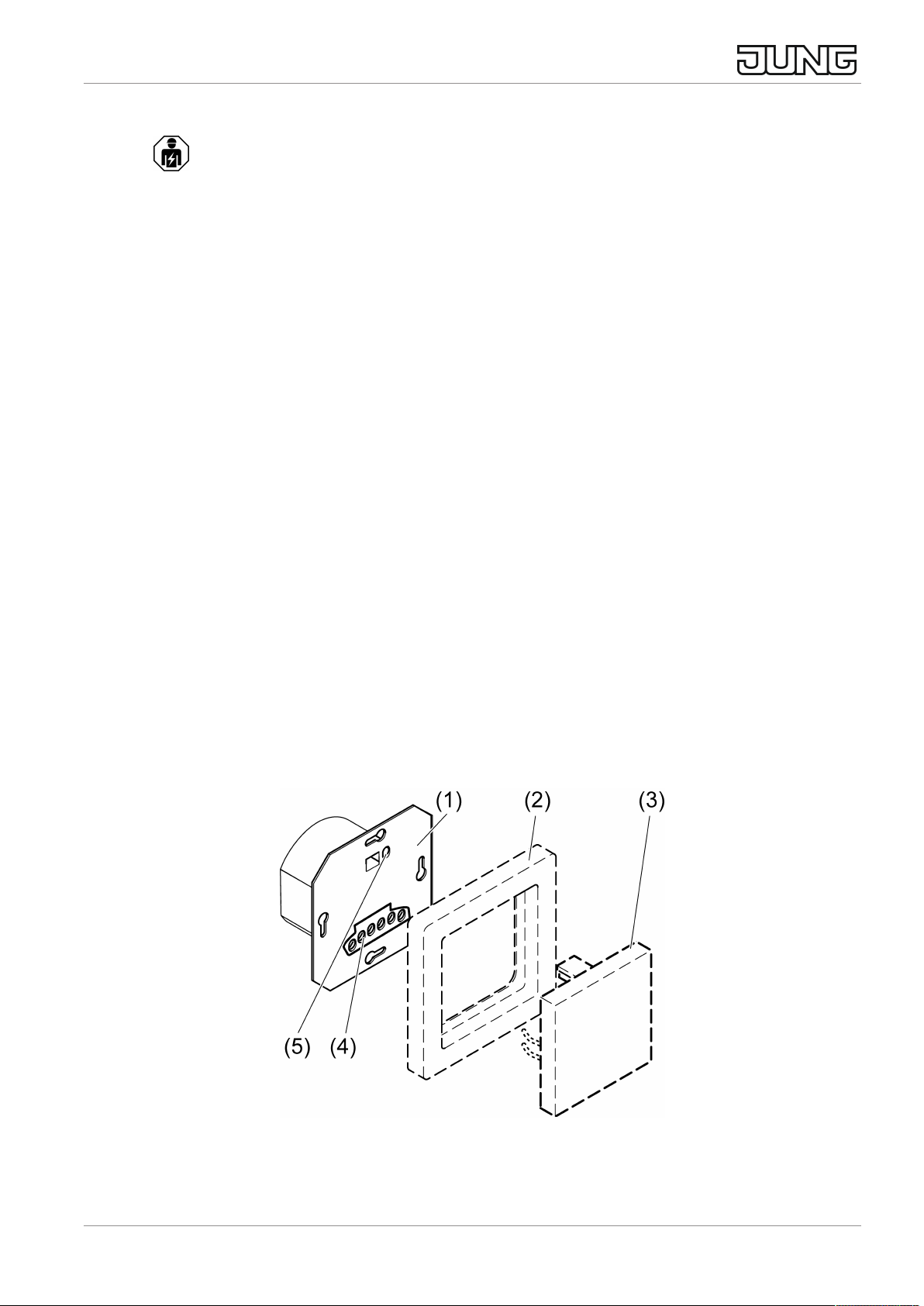
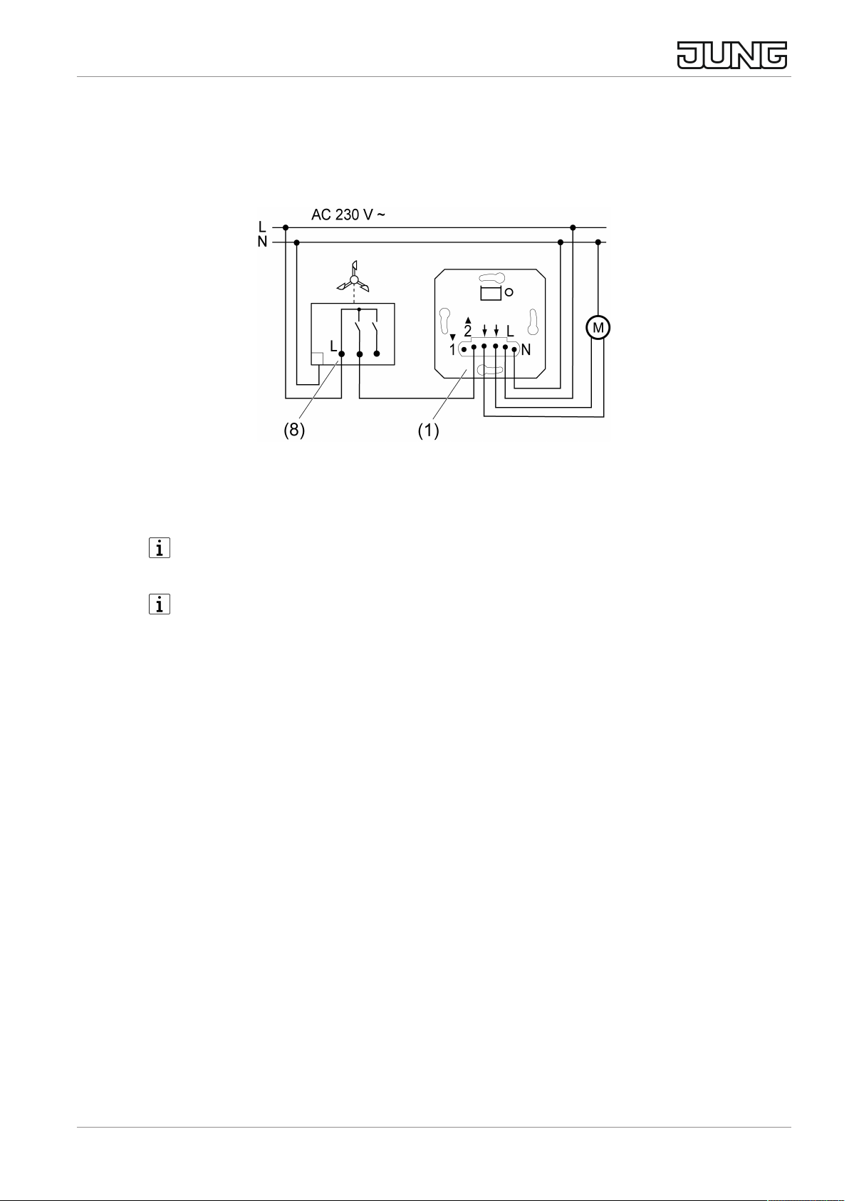
■ Connecting Venetian blind insert (1) (see figure 2). Note clampable cable
cross-sections (see figure 3). Optional: Connection of an extension (6). A
mechanical venetian blind push-button or Venetian blind switch can also be
used as an extension instead of the venetian blind insert.
■ Install Venetian blind control in appliance box, terminals must be at the bot-
tom. Recommendation: Use deep appliance box.
■ Switch on mains voltage.
The TEST button also allows activation of the connected motor without a cover, e.g.
to be able to set the end positions of the motor.
■ Press the TEST button for less than 1 second.
Blind/shutter moves in the bottom end position direction.
■ Press button TEST longer than 1 second.
Blind/shutter moves in the upper end position direction.
If the blind/shutter moves in the wrong direction, you can use the reverse func-
tion of the insert.
■ Reverse function: Press the TEST button for more than 10 seconds.
The insert signals successful reversing of the outputs through quick activation
in the Down direction and then in the Up direction. The new direction of travel
is saved to power failure-proof memory.
■ Attach the frame and the cover.
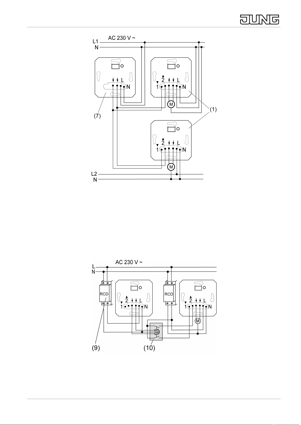
If multiple circuit breakers supply dangerous voltages to the device or load,
couple the circuit breakers or label them with a warning, to ensure disconnec-
tion is guaranteed.
As long as an Up command is active on extension unit input 2 (wind alarm),
the Venetian blind cannot be operated either manually or automatically.
Integrating the device into a group control
The Venetian blind insert can be integrated into a group control (see figure 4), either
for local control (1) or as a master unit (7).
Universal blinds insert
6 / 9
82595633 19.08.2022
J0082595633

Image4: Connection example of group control
■ Connect the Venetian blind inserts according to the connection example
(see figure 4). The Venetian blind inserts can also be connected to different
phase conductors.
Implementing Venetian blind control via various residual current devices
In order to prevent undesirable triggering of the residual current devices (9), the elec-
tric circuits must be decoupled by means of a Venetian blind cutoff relay (10).
Image5: Connection example of two RCD circuits
■ Connect the devices according to the connection example (see figure 5).
Universal blinds insert
7 / 9
82595633 19.08.2022
J0082595633

Implementing a wind alarm
Wind sensors serve to protect a Venetian blind from being destroyed by a strong
wind. The Venetian blind is moved to a safe end position and locked there until the
wind drops below the set threshold value.
Image6: Connection example of wind sensor
■ Connect the wind sensor (8) according to the connection example
(see figure 6). The wind alarm is implemented via extension input 2.
In order to use the wind alarm for all external Venetian blinds of a building, the
wind sensor must be connected to extension unit input 2 of the master control.
As long as an Up command is active on extension unit input 2, the Venetian
blind cannot be operated either manually or automatically.
Resetting overload switch-off
If the electronic overload cut-off has triggered, disconnect the device from the mains
for a short time.
6 Technical data
Rated voltage AC 230 V ~
Mains frequency 50 / 60 Hz
Standby power: 0.1…0.5W, depending on the cover
Ambient temperature -5 ... +45 °C
Storage/transport temperature -20 ... +70 °C
Running time approx. 120 s
Connected load
Motors 700 W
7 Warranty
The warranty is provided in accordance with statutory requirements via the specialist
trade.
Universal blinds insert
8 / 9
82595633 19.08.2022
J0082595633

ALBRECHT JUNG GMBH & CO. KG
Volmestraße 1
58579 Schalksmühle
GERMANY
Telefon: +49 2355 806-0
Telefax: +49 2355 806-204
www.jung.de
Universal blinds insert
9 / 9
82595633 19.08.2022
J0082595633
Other manuals for 1731JE
1
This manual suits for next models
1
Table of contents
Other Jung Household Appliance manuals