Jung RS8REGHE User manual

Table of Contents
1 Safety instructions.............................................................................................................3
2 Device components...........................................................................................................3
3 Intended use .....................................................................................................................4
4 Product characteristics......................................................................................................4
5 Operation ..........................................................................................................................5
6 Information for electrically skilled persons ........................................................................7
6.1 Mounting and electrical connection........................................................................ 7
6.2 Commissioning .................................................................................................... 13
6.2.1 Settings for sensor modules and push-button sensor modules............... 15
7 Technical data.................................................................................................................16
8 Troubleshooting ..............................................................................................................18
9 Accessories.....................................................................................................................19
10 Warranty..........................................................................................................................19
2 / 19
82556953 03.02.2023
J0082556953
Relay station universal, 8-gang

1 Safety instructions
Electrical devices may only be mounted and connected by electrically skilled
persons.
Serious injuries, fire or property damage possible. Please read and follow manual
fully.
Danger of electric shock. Always disconnect before carrying out work on the device
or load. In so doing, take all the circuit breakers into account, which support danger-
ous voltages to the device and or load.
Danger of electric shock. During installation and cable routing, comply with the regu-
lations and standards which apply for SELV circuits.
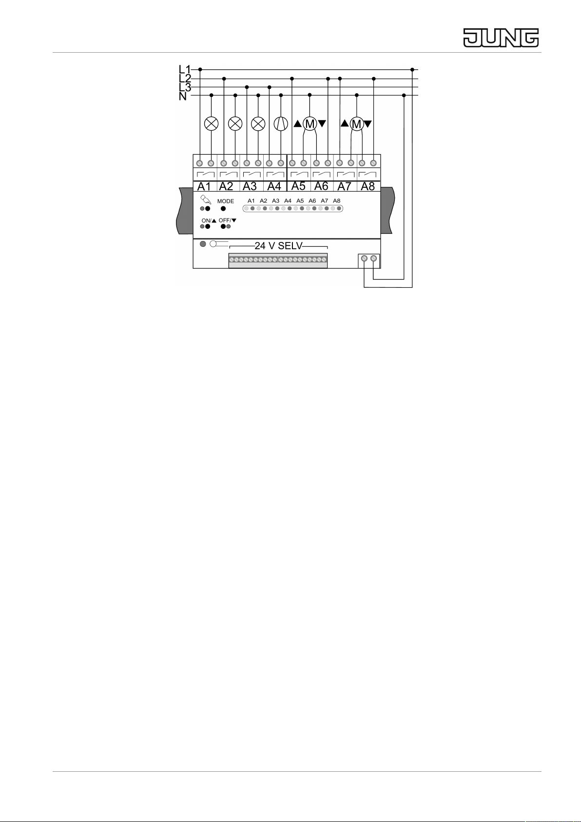
Danger of electric shock on the SELV/PELV installation. Do not connect loads for
mains voltage and SELV/PELV together on a single switch actuator.
Do not connect any three-phase motors. Device can be damaged.
Risk of injury. Use the device only for controlling Venetian blind and roller shutter mo-
tors or awnings. Do not use it to switch other loads.
Use only Venetian blind motors with mechanical or electronic limit switches. Check
the limit switches for correct mastering. Observe the information on the motors from
the manufacturing company. Device can be damaged.
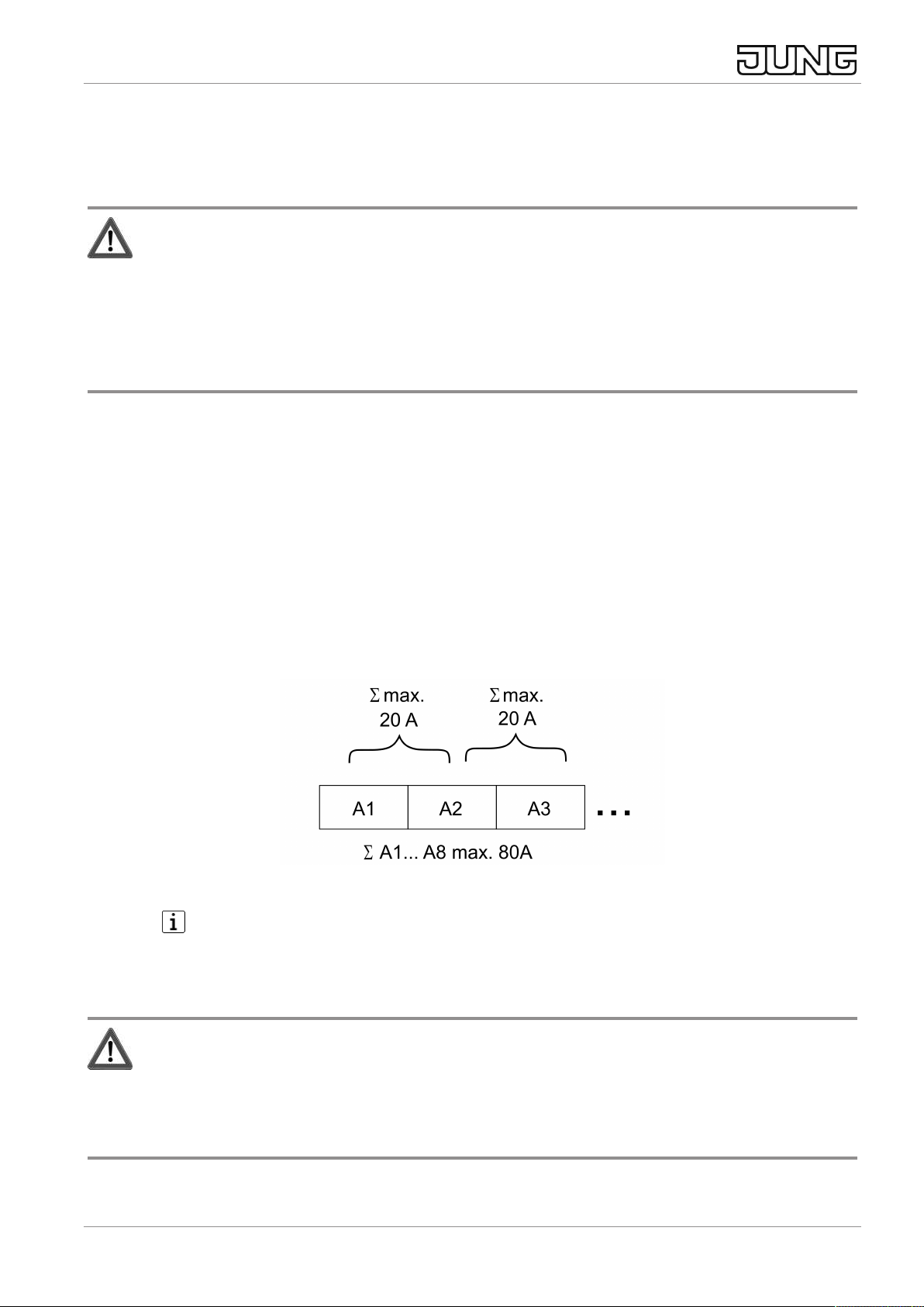
For the parallel connection of several motors to an output, it is essential to observe
the information from the manufacturing company and use a cut-off relay if necessary.
The motors may be destroyed.
This manual is an integral part of the product, and must remain with the customer.
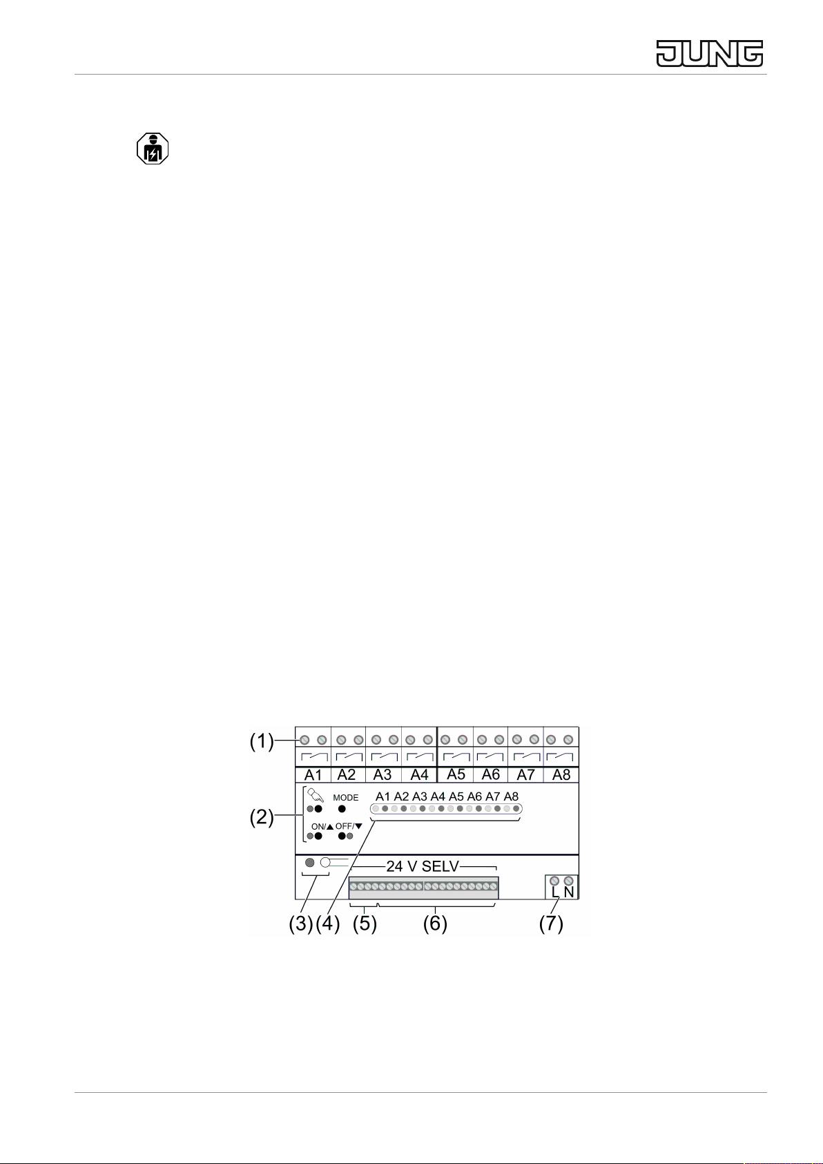
2 Device components
Image1: Device components
(1) Connection for loads A1 ... A8
(2) Keypad for local control
(3) Central switching mode, change-over button and status LED for central function
(4) Status LED for load outputs
Relay station universal, 8-gang
3 / 19
82556953 03.02.2023
J0082556953

(5) Connection of control sections or control voltage
(6) Activation outputs A1'... A8' / Switching outputs E1 ... E8
(7) Connection for mains supply
3 Intended use
– Switching of lighting, single-phase fan motors, electrically driven Venetian
blinds, shutters, awnings and similar hangings
– Operation by means of sensor modules, push-button sensor modules, 24 V
push-button sensors, 24 V push-button sensor modules or unlit buttons
– Installation in sub-distribution units on DIN rail according to DIN EN 60715
4 Product characteristics
– Local control
– Keypad for operation of the relay station
– Control outputs A1' ... A8' for activation of feedback LEDs on the control sec-
tions
– Switch operation
– Push-button operation
– Venetian blind operation with slat adjustment
– Mixed operation possible, example: load outputs A1 ... A3 for switch operation,
load output A4 for push-button operation, load outputs A5 ... A8 for Venetian
blind operation
– Central function Central ON, Central OFF: switching the load outputs on or off
together
– Operation with 24 V push-button sensors or 24 V push-button sensor modules:
parallel switching of up to four relay or dimmer stations possible
– Operation with sensor modules or push-button sensor modules: parallel
switching of two relay or dimmer stations possible
Behaviour after a mains voltage failure
After the mains voltage returns, all load outputs are switched off and have to be
switched on again.
Relay station universal, 8-gang
4 / 19
82556953 03.02.2023
J0082556953

5 Operation
Image2: Control panel
(4) Status LED for load outputs A1 ... A8 in normal operation
(9) c button for local control
(10) LED c on: local control or programming mode active
(11) Button ON/n: switching on the load output or setting the operating mode
(12) LED ON/n: status LED for load output or indication of operating mode
(13) Button OFF/o: switching off the load output or setting the operating mode
(14) LED OFF/o: status LED for load output or indication of operating mode
(15) MODE button for programming mode
Local control of the load outputs
The load outputs are operated with the integrated keypad (2).
■ Press the c button briefly.
Red status LED A1 (4) flashes, LED c (10) lights up.
Local control is active. Load output A1 can be controlled.
The LEDs ON/n (12) and OFF/o (14) indicate the switching state of the load
output.
■ Actuate the load output with the ON/n (12) and OFF/o (14) buttons.
Push-button outputs: operation only with the ON/n button (12)
Venetian blind outputs, long: move venetian blind up/down, short: stop slat ad-
justment or Venetian blind
■ Actuate the c button briefly to switch to the next load output.
The red status LED (4) of the next load output A2 ... A8 flashes.
■ Operate load output as described above.
Switching off local control
■ Press the c button as many times as necessary until the local control is
switched off. Alternatively, do not press any button for 15 s.
Relay station universal, 8-gang
5 / 19
82556953 03.02.2023
J0082556953

The red status LEDs A1 ... A8 (4) indicate the switching status of the load out-
puts.
The load outputs retain the switch position previously set. A blind movement
that has been started will be completed.
Operating using control sections
Button output
■ Press the button.
The button output is switched on as long as the button is pressed.
Switching output
■ Press the button
The switching output switches on or off, depending on the switching state.
Venetian blind output
■ Press and hold the button to move up/down.
The Venetian blind output for the corresponding direction is switched on. The
switch-on time of the relay is two minutes.
The motion can be stopped or the slats adjusted by briefly pressing the button.
Central function
The central function Central ON and Central OFF can be assigned to each load out-
put separately during commissioning (see Setting the operating mode and central
function for the load outputs A1 ... A8).
■ Press the button for Central ON.
The switching outputs switch on.
Venetian blinds move to the upper end position. Venetian blinds that are mov-
ing down will stop.
The push-button outputs are switched on for 0.3 seconds.
■ Press the button for Central OFF.
Switching outputs switch off.
Venetian blinds move to the lower end position. Venetian blinds that are mov-
ing up will stop.
The push-button outputs are switched on for 0.3 seconds.
Relay station universal, 8-gang
6 / 19
82556953 03.02.2023
J0082556953

6 Information for electrically skilled persons
6.1 Mounting and electrical connection
DANGER!
Electric shock when live parts are touched.
Electric shocks can be fatal.
Always disconnect before carrying out work on the device or load. For this, switch off
all corresponding circuit breakers, secure against being switched on again and check
that there is no voltage. Cover up adjacent live parts.
Mounting the device
■ Observe the temperature range. Ensure sufficient cooling.
■ Mount device on DIN rail. The load terminals (1) must be at the top
(see figure 1).
Connecting the mains voltage
■ Connect the mains voltage to connection (7) (see figure 4).
Connecting loads
■ Observe the current carrying capacity (see figure 3)
Image3: Current carrying capacity of load outputs
In Venetian blind operation, each pair of adjacent load outputs forms a Vene-
tian blind output. In each case the left-hand load output A1, A3, ... is intended
for the upwards direction, and the right-hand load output A2, A4, ... for the
downwards direction.
CAUTION!
Overloading the device leads to excessive heating.
Damage to the device and the connected cables may result.
Do not exceed the maximum current carrying capacity.
■ Connect loads as shown in the wiring example (see figure 4).
Relay station universal, 8-gang
7 / 19
82556953 03.02.2023
J0082556953

Image4: Wiring example for mains voltage and loads
Information on the operation points
– Operation take place using the devices listed under Accessories.
– Observe the technical data, especially the maximum number of sensor mod-
ules and push-button sensor modules, current carrying capacity of the activa-
tion outputs and switching inputs.
– Do not connect any sensor modules (17) or push-button sensor modules (17)
when operating with 24 V push-button sensors (16), 24 V push-button sensor
modules (16) and push-buttons (18).
24 V push-button sensors, 24 V push-button sensor modules (16)
■ Establish the connection according to the connection example (see figure 5).
Relay station universal, 8-gang
8 / 19
82556953 03.02.2023
J0082556953

Image5: Connection example with 24 V push-button sensor, 24 V push-button
sensor module, 4-gang
Sensor modules, push-button sensor modules (17)
■ Establish the connection according to the connection example (see figure 6).
Image6: Connection example of sensor module or push-button sensor module
Relay station universal, 8-gang
9 / 19
82556953 03.02.2023
J0082556953

Push-button (18)
■ Establish the connection according to the connection example (see figure 7).
Image7: Push-button connection example
Connection of one 24 V push-button sensor or 24 V push-button sensor module to
several relay stations
When operating with 24 V push-button sensors or 24 V push-button sensor modules,
they can be connected to up to four relay stations. To do this, the negative poles of
the individual relay stations have to be connected to each other. It is possible, for ex-
ample, to use a 24 V push-button sensor to switch load outputs of several relay sta-
tions or to implement central control of several relay stations.
■ Connect the 24 V push-button sensor according to the connection example.
Here, channel 1 of the 24 V push-button sensor switches load output A1 of the
right relay station and channel 2 switches load output A2 of the left relay sta-
tion (see figure 8).
Relay station universal, 8-gang
10 / 19
82556953 03.02.2023
J0082556953

Image8: Connection example with a 24 V push-button sensor to two relay stations
Wiring example for central control. For the example, the central function must be
switched on at both relay stations (see chapter Switching on the central function of
the relay station).
■ Connect the 24 V push-button sensor according to the connection example.
Here, channel 7 of the 24 V push-button sensor switches Central ON and
channel 8 switches Central Off (see figure 9)
The feedback LEDs of the 24 V push-button sensors are connected only to the
activation outputs of one relay station. This relay station then indicates the
status of the load outputs, standing in for all of the relay stations.
Relay station universal, 8-gang
11 / 19
82556953 03.02.2023
J0082556953

Image9: Connection example for Central ON, Central OFF
Switching on the central function of the relay station
For central operation using 24 V push-button sensors, 24 V push-button sensor mod-
ules or push-buttons, the central function must be activated on the relay station.
The sensor module and push-button sensor module are used to set the central
function on the modules.
■ Press the button Central Switching Mode (3) for approx. five seconds until the
status LED (3) lights up in red (see figure 1).
The red and green status LEDs (4) (see figure 1) for load output A8 flash al-
ternately.
Activation output A8' is input for Central OFF.
Switch input E8 is input for central ON.
Load output A7 is in push-button operation.
When the central function is activated, load output A8 has no function.
Switching off the central function of the relay station
■ Press the button Central Switching Mode (3) for approx. five seconds until the
status LED (3) lights up in green (see figure 1).
The red status LED (4) (see figure 1) for load output A8 is off.
The green status LED (4) for load output A8 indicates push-button or switching
operating modes.
Relay station universal, 8-gang
12 / 19
82556953 03.02.2023
J0082556953

Connecting one sensor module or push-button sensor module to two relay stations
Sensor modules or push-button sensor modules can operate two relay stations to-
gether. This requires the connection of both relay stations in parallel. To do this, the
relay stations and sensor modules must have at least version V02. To do this, the
device address of a relay station must be changed (see "Setting the device ad-
dress").
Even relay stations switched in parallel may only have four sensor modules or
push-button sensor modules connected to them.
■ Connect the relay stations to the same phase conductor.
■ Connect the sensor module or push-button sensor module to the relay stations
according to the connection example (see figure 10).
Image10: Connection example of one sensor module or push-button sensor module
to two relay stations
6.2 Commissioning
Setting the operating mode and central function of load outputs A1 ... A8
The status LEDs (4) of the load outputs have the following meaning in normal opera-
tion:
LED off lights up flashes
green LED Buttons Switching Venetian blind
red LED Load output OFF Load output ON --
In the state as supplied all load outputs are set to Venetian blind operation. The oper-
ating mode for the load outputs is set by means of the following steps. The settings
are retained in the event of a mains failure.
Relay station universal, 8-gang
13 / 19
82556953 03.02.2023
J0082556953

■ Press the MODE button (15) (see figure 2) for approx. 5 seconds.
The LED c (10) (see figure 2) lights up. Programming mode is switched on.
The green status LED (4) for the load output A1 or in Venetian blind mode A1
and A2 flash. The operating mode can be set for output A1.
CAUTION!
Danger of destruction from wrong operating mode.
A simultaneous current feed in both directions of travel can destroy the device and
the connected Venetian blind motors.
Before setting the operating mode, check what loads are connected.
■ Set the operating mode for load output A1, see table.
Operating mode Button LED
Switching Press ON/n (11) ON/n (12) lights up
Buttons Press OFF/o (13) OFF/o (14) lights up
Venetian blind Press ON/n (11)
and OFF/o (13) simultan-
eously
ON/n (12) and OFF/o
(14) light up
If a load output A1 ... A8 is set to Venetian blind operation, the setting is auto-
matically adopted for the second associated load output.
■ Press the MODE (15) button briefly.
The operating mode of the next load output can be set.
After the last load output is set, the mode for setting the central function is ac-
tivated automatically.
In the state as supplied the central function is assigned to all of the load out-
puts.
In the case of Venetian blind outputs, the central function can be set individu-
ally for each direction of travel. Thus for example in the case of Central OFF
the Venetian blind moves to the lower end position, but in the case of Central
OFF the Venetian blind does not move.
The red or green status LED (4) of output A1 flashes.
■ Set the central function for load output A1, see table.
Operating mode Button LED
Central function switched
on
Press ON/n (11) Red status LED (4) flashes.
Central function switched
off
Press OFF/o (13) Green status LED (4)
flashes
■ Press MODE button briefly.
Relay station universal, 8-gang
14 / 19
82556953 03.02.2023
J0082556953

The central function for the next load output can be set.
Exit programming mode
■ Press the MODE button (15) repeatedly until the LED c (10) goes out.
The status LEDs (4) indicate the operating mode and the switching status of
load outputs A1 ... A8.
Programming mode is automatically terminated after 15 seconds without actu-
ating a button.
6.2.1 Settings for sensor modules and push-button sensor modules
Setting the device address
If two relay stations are connected in parallel, the device address of a relay station
must be reprogrammed before the sensor modules or push-button sensor modules
are commissioned. In the state as supplied each relay station has the device address
1.
Prerequisite: sensor modules or push-button sensor modules are connected.
■ Press the ON/n and OFF/o buttons simultaneously for approx. 3 seconds.
The green status LED (4) of output A1 flashes. Device has the device address
1.
■ Press the ON/n or OFF/o buttons briefly.
The green status LED (4) of output A2 flashes. Device address 2 has been
set.
■ Press the ON/n and OFF/o buttons simultaneously for approx. 3 seconds.
The relay station switches to normal operation.
Switching on the status message for sensor modules and push-button sensor
modules
When operating with sensor modules or push-button sensor modules, a status mes-
sage must be transmitted regularly. In the state as supplied this status message is
switched off.
Prerequisite: sensor modules or push-button sensor modules are connected.
■ Press the ON/n and OFF/o buttons simultaneously for approx. 3 seconds.
The green status LED (4) of output A1 or output A2 flashes.
■ Press MODE button briefly.
The green status LED (4) of all outputs flashes briefly. The regular status mes-
sage is switched on.
■ Press the ON/n and OFF/o buttons simultaneously for approx. 3 seconds.
Relay station universal, 8-gang
15 / 19
82556953 03.02.2023
J0082556953

The relay station switches to normal operation.
The regular status message is switched off in the same way as it is switched
on. All red status LEDs (4) of the outputs flash briefly for acknowledgement.
Cloning sensor modules or push-button sensor modules
"Cloning" is used to transfer the button assignments of a module to other modules.
Only identical devices and the same release version can be cloned - sensor module
to sensor module or push-button sensor module to push-button sensor module. Con-
trol of the relay station is not possible during cloning mode.
Preconditions:
Several sensor modules or push-button sensor modules are connected to the relay
station.
Button assignments have been made on a module.
■ Press the buttons MODE (15) (see figure 2) and Central Switching Mode (3)
simultaneously (see figure 1) until the LEDs c, ON/n and OFF/o flash
(see figure 2).
The relay station and modules are in cloning mode.
■ Press a button within approx. 2 minutes on the module to be cloned.
■ Press a button on a different module within approx. 2 minutes.
The module has adopted the button assignments, and cloning mode is termin-
ated.
■ Repeat the steps described above for additional modules.
Cloning mode cannot be terminated manually. To abort cloning mode once it
has started, wait 2 minutes without pressing any sensor module or push-but-
ton sensor module.
If cloning mode is activated on the relay station when there are no sensor
modules or push-button sensor modules connected, cloning mode will be ter-
minated automatically after 3 minutes.
For additional information, e.g. on signalling of the modules, please refer to the
instructions for the module in question.
7 Technical data
Rated voltage AC 230 / 240 V ~
Mains frequency 50 / 60 Hz
Standby power approx. 0.5 W
Power loss 12.5 W
Ambient temperature -5 ... +45 °C
Storage/transport temperature -25 ... +70 °C
Installation width 144 mm / 8 HP
Relay station universal, 8-gang
16 / 19
82556953 03.02.2023
J0082556953

Terminals -, +
Control voltage DC 24 V SELV
Current carrying capacity Ʃ 80 mA
Total length of control cable max. 100 m
Number
Sensor modules / push-button sensor modules 4
24 V push-button sensors / 24 V push-button
sensor modules
Type-dependent
Switching inputs E1 ... E8
Control voltage DC 24 V SELV
Resistance Ri 200 kΩ
Activation outputs A1' ... A8'
Control voltage DC 24 V SELV
Current carrying capacity 10 mA
Resistance CRI 330 Ω
Connection of activation outputs / switching outputs / con-
trol sections
Single stranded 1.5 mm²
Finely stranded with conductor sleeve 0.75 mm²
Finely stranded without conductor sleeve 1 mm²
Connection of rated voltage / load outputs
Single stranded 0.5 ... 4 mm²
Finely stranded with conductor sleeve 0.14 ... 2.5 mm²
Finely stranded without conductor sleeve 0.34 ... 4 mm²
Load outputs A1 ... A8
Contact type µ contact, potential-free NO contact
Rated voltage AC 230 / 240 V ~
Minimum switching voltage AC 12 V~
Switching current per device Σ 80A
Switching current, adjacent load outputs Σ 20A
Switching current per channel at AC 250
V~
Fluorescent lamps 16AX
Capacitive load DIN EN IEC 61058-1 max. 16 A (140 μF)
Switch-on current 200 μs max. 800 A
Switch-on current 20 ms max. 165 A
Minimum switching current AC 100 mA
Connected load per channel for AC 230
V~
Ohmic load 3000 W
Relay station universal, 8-gang
17 / 19
82556953 03.02.2023
J0082556953

Incandescent lamps 3000 W
HV halogen lamps 2500 W
Electronic transformers 1500 W
Inductive transformers 1200 VA
Fluorescent lamps
uncompensated 1000 VA
parallel compensated 1160 VA (140 μF)
twin-lamp circuit 2300 VA (140 μF)
Mercury vapour lamps
uncompensated 1000 W
parallel compensated 1160 W (140 μF)
Electronic ballast Type-dependent
Venetian blind motors, fan motors 1380 VA
Switch-over time for direction change approx. 1 s
Switch-on time for Venetian blind opera-
tion
approx. 2 min
8 Troubleshooting
No control is possible via control sections.
Cause 1: local control is switched on.
Switch off local control (see Operation chapter).
Cause 2: programming mode is switched on.
Switch off programming mode (see Commissioning chapter).
Load output A8 cannot be controlled.
Cause: The central function Central ON, Central OFF at the relay station is switched
on.
Switch off the central function (see chapter Mounting and electrical connection).
Set the operating mode for load output A8 (see Commissioning chapter).
No Venetian blind operation can be set for load outputs A7 ... A8
Cause: The central function Central ON, Central OFF at the relay station is switched
on.
Switch off the central function (see chapter Mounting and electrical connection).
Set Venetian blind operating mode for load outputs A7 ... A8 (see Commission-
ing chapter).
Venetian blind at load outputs A7 ... A8 can only be opened.
Cause: The central function Central ON, Central OFF at the relay station is switched
on.
Relay station universal, 8-gang
18 / 19
82556953 03.02.2023
J0082556953

Switch off the central function (see chapter Mounting and electrical connection).
Set Venetian blind operating mode for load outputs A7 ... A8 (see Commission-
ing chapter).
The load output is switched off after 2 minutes.
Cause: Venetian blind operating mode has been set for the load output.
Set the operating mode (see Commissioning chapter).
Two adjacent load outputs, e.g. A1 ... A2, A3 ... A4, ... cannot be switched on
simultaneously.
Cause: Venetian blind operating mode has been set for the load outputs.
Set the operating mode (see Commissioning chapter).
Both directions of travel of a Venetian blind motor can be switched on
simultaneously.
Cause 1: The load outputs have the wrong operating mode.
Set venetian blind operating mode for the load outputs (see Commissioning
chapter).
Cause 2: The Venetian blind motor is connected to the wrong load outputs.
Check the installation (see chapter Mounting and electrical connection)
9 Accessories
Sensor module 8-gang Art.-no.: SM1608
Push-button module Art.-no.: 4008TSM
Push-button module 24VAC/DC F40 Art.-no.: 42..TSM
Push-button module 24VAC/DC F50 Art.-no.: ..52..TSM
10 Warranty
The warranty is provided in accordance with statutory requirements via the specialist
trade.
ALBRECHT JUNG GMBH & CO. KG
Volmestraße 1
58579 Schalksmühle
GERMANY
Telefon: +49 2355 806-0
Telefax: +49 2355 806-204
www.jung.de
Relay station universal, 8-gang
19 / 19
82556953 03.02.2023
J0082556953
Table of contents
Other Jung Relay manuals
Popular Relay manuals by other brands

F&F
F&F BIS-411 1R1Z quick start guide

BECKWITH ELECTRIC
BECKWITH ELECTRIC Syncrocloser M-3410A Instruction book

Hella
Hella 4RD 980 830-001 / 3099 Operation and installation instructions

TECO
TECO SG2-12HT-D user manual

Siemens
Siemens 7UG0583-1CU20 operating instructions

Compact Electric
Compact Electric CDMR-62 user manual