Junt KNX Smart Panel 8 User manual
Operating instructions
ALBRECHT JUNG
GMBH & CO. KG
Volmestraße 1
58579 Schalksmühle
GERMANY
Tel. +49 2355 806-0
Fax +49 2355 806-204
www.jung.de
KNX Smart Panel 8
Ref.-no.: SP 0081 U
04/2021
0024022000
GB


Table of contents
1SP 0081 U
Table of contents
1 Safety instructions and device components ....................... 2
1.1 Safety instructions..................................................................... 2
1.2 Device components ................................................................... 2
2 Function .................................................................................. 3
2.1 System information.................................................................... 3
2.2 Intended use ............................................................................... 3
2.3 Product characteristics ............................................................. 3
3 Installation and electrical connection .................................. 4
3.1 Information for electrically skilled persons............................. 4
3.2 Mounting in installation box or appliance box........................ 4
3.3 Mounting the adapter................................................................. 5
3.4 Connection ................................................................................. 6
3.5 Mounting the Smart Panel......................................................... 7
4 Commissioning....................................................................... 8
4.1 Switching on............................................................................... 8
4.2 Settings – Overview of the menu structure ............................. 8
4.3 Opening the settings ................................................................. 8
4.4 Selecting the language .............................................................. 8
4.5 Selecting date and time ............................................................. 9
4.6 Changing the system password ............................................... 9
8SGDWLQJWKH¿UPZDUH ............................................................... 9
2SHUDWLRQDQGFRQ¿JXUDWLRQ ............................................... 10
6 Cleaning ................................................................................ 10
7 Technical data........................................................................11
8 Accessories .......................................................................... 12
9 Warranty ................................................................................ 12
2
SP 0081 U
Safety instructions and device components
KNX Smart Panel 8
1 Safety instructions and device components
1.1 Safety instructions
Electrical devices may only be mounted and
connected by electrically skilled persons.
6HULRXVLQMXULHV¿UHRUSURSHUW\GDPDJHSRVVLEOH3OHDVH
read and follow manual fully.
Danger of electric shock. During installation and cable
routing, comply with the regulations and standards which
apply for SELV circuits.
These instructions are an integral part of the product and
must remain with the end customer.
1.2 Device components
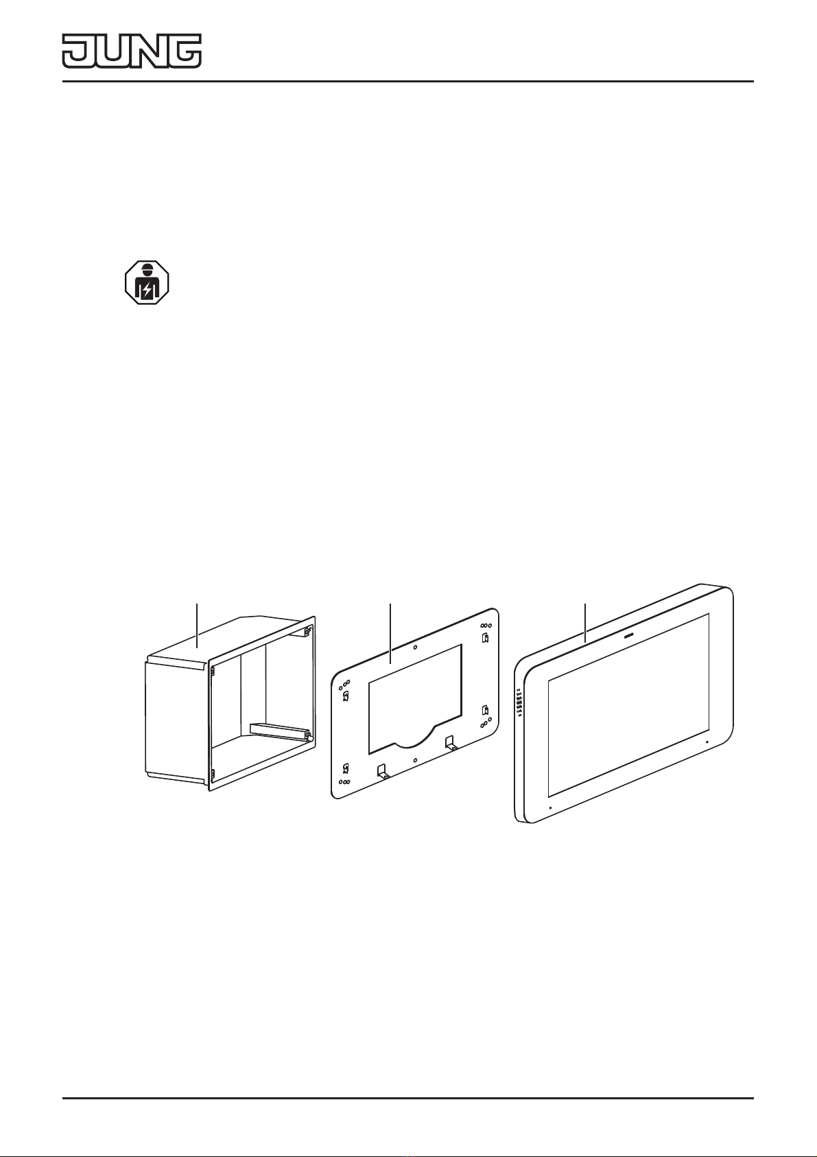
Fig. 1: Device components
1 Installation box
2 Adapter
3 Smart Panel
123

3
SP 0081 U
Function
2 Function
2.1 System information
This device is a product of the KNX system and conforms to
the KNX Directives. Detailed knowledge attained through KNX
training is a prerequisite for understanding.
The device is planned, installed and commissioned by means
of an external of external project planning software. The latest
software version and the technical descriptions can be found on
our website at all times.
2.2 Intended use
- Visualising and operating system statuses and information on
building automation
- For horizontal installation (recommended) or vertical
installation
- 0RXQWLQJLQDÀXVKPRXQWHGLQVWDOODWLRQER[UHIQR(%*
RU6&(%*RURQDSSOLDQFHER[DFFRUGLQJWR(1
(recommendation: at a depth of approx. 60 mm)
2.3 Product characteristics
- High-resolution HD display
- Proximity sensor
- Capacitive touch screen
- Cleaning mode with touch screen lock
- Fanless, without mechanical moving parts
- Integrated bus coupling unit
- Graphical user interface for visualisation and operation of KNX
devices

4
SP 0081 U
Installation and electrical connection
3 Installation and electrical connection
3.1 Information for electrically skilled persons
DANGER
Electrical shock on contact with live parts in the
installation environment.
Electrical shocks can be fatal.
Before working on the device, disconnect the power
and cover live parts in the area!
3.2 Mounting in installation box or appliance box
7KH6PDUW3DQHOLVGHVLJQHGIRULQVWDOODWLRQLQDÀXVKPRXQWHG
LQVWDOODWLRQER[UHIQR(%*RU6&(%*7KH6PDUW3DQHO
adapter is screwed onto the installation box.
Installation boxes from other manufacturers must match the
overall dimensions and holes of the adapter and the Smart
Panel. (see technical data for overall dimensions)
7KHLQVWDOODWLRQER[PXVWEHSUHFLVHO\DOLJQHGDQGPRXQWHGÀXVK
in the wall.
Alternatively, an appliance box according to EN 60670-1 can be
used for mounting the Smart Panel. The Smart Panel adapter is
not mounted directly on the appliance box, but on the wall.
The recommended depth of the appliance box is approx. 60 mm.
5
SP 0081 U
Installation and electrical connection
3.3 Mounting the adapter
83
58
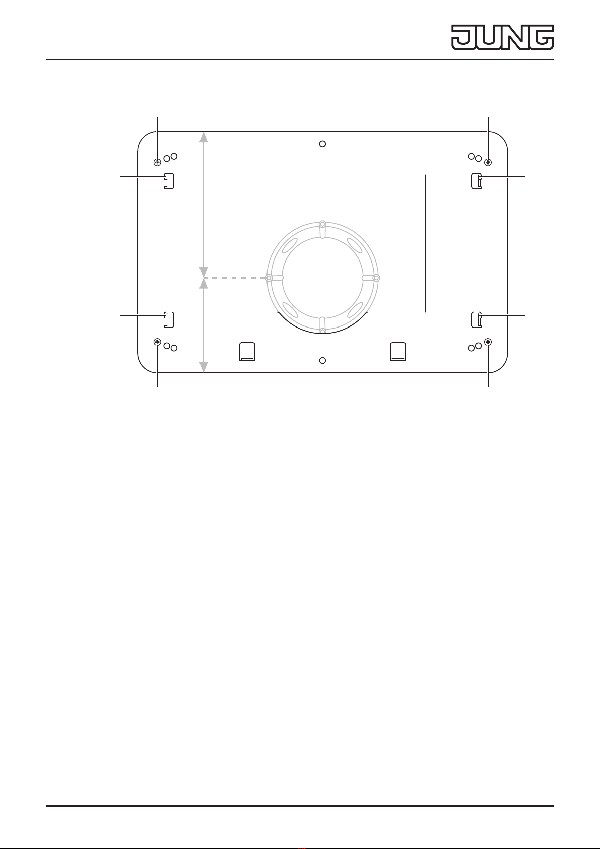
Fig. 2: Montage Adapter
1 Adapter locking screw
2 Fixing hooks
• Mount the adapter on the installation box with a total of four
ORFNLQJVFUHZV¿J
When mounting on an appliance box, the adapter must be
mounted on the wall. The adapter must be placed in such
a way that the appliance box is located in the indentation of
the adapter. In this way, the wall box is located slightly to the
bottom of the adapter.
11
11
2
2
2
2
6
SP 0081 U
Installation and electrical connection
3.4 Connection
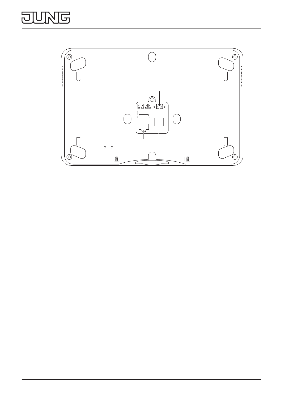
Fig. 3: Connection
3 Power supply 5 LAN/Ethernet
486% 6 KNX bus
Requirements:
- .1;(,%EXVFRQQHFWLRQ
- Power supply via power supply adapter, ref. no.:
NT 2415 REG VDC
- )RU¿UPZDUHXSGDWHVVXSSRUW,3FDPHUDVRURSHUDWLRQYLD
mobile end devices: Ethernet connection
• &RQQHFWWKHSRZHUVXSSO\DQG.1;¿J
• Connect LAN (5) optionally.
iDo not connect any other products and loads outside the
KNX standard to the bus output. The bus communication
FRXOGEHDႇHFWHGE\WKLV
4
6
3
5

7
SP 0081 U
Installation and electrical connection
3.5 Mounting the Smart Panel
Fig. 4: Montage Smart Panel
7 Openings for wall mounting
8 Smart Panel locking screws
• Place the openings for wall mounting (7) on the Smart Panel
RQWKH¿[LQJKRRNVRQWKHDGDSWHU¿JDQG¿J
To do this, place the openings for wall mounting above the
hooks and engage them downwards.
• Fasten the Smart Panel to the adapter on the underside with a
WRWDORIWZRORFNLQJVFUHZV¿J
88
7
7
7
7

8
SP 0081 U
Commissioning
4 Commissioning
4.1 Switching on
After connecting, the device is switched on automatically and the
operating system is started.
After the start-up process, you must make the settings for
commissioning.
4.2 Settings – Overview of the menu structure
- General
- Language
- Date/time
- Design
- Display
- Advanced
- System password
4.3 Opening the settings
• Select the JUNG logo in the main menu (JUNG Launcher).
Password entry opens.
• Enter the system password.
The default system password is “0000“.
The settings open.
4.4 Selecting the language
• Open the settings.
• Select the menu “General”.
• Select the submenu “Language”.
Available languages are displayed.
• Select the language.
The language is selected.
This manual suits for next models
1
Table of contents
Other Junt Tablet manuals


