Jupiter Avionics JA44-001 User manual

Rev
B Page i
JA44-001
High Impedance Headset to
Low Impedance Intercom Adapter
Installation and Operating Manual
Rev A
Jupiter Avionics Corporation
1959 Kirschner Road
Kelowna BC
Canada V1Y 4N7
Tel: +1 778 478 2232
Toll-Free: 1 855 478 2232
www.jupiteravionics.com

JA44-001 High Impedance Headset to Low Impedance Intercom Adapter
Installation and Operating Manual
Rev A Page ii
Copyright 2018 Jupiter Avionics Corp.
All rights reserved
Jupiter Avionics Corporation (JAC) permits a single copy of this manual to be printed or downloaded for the express use
of an installing agency. Any such electronic or printed copy of this manual must contain the complete text of this copyright
notice. Any unauthorized commercial distribution of this manual is strictly prohibited. Except as described above, no part
of this manual may be reproduced, copied, transmitted, disseminated, downloaded, or stored in any storage medium for
any purpose without the express prior written consent of JAC.
RECORD OF REVISIONS
Revision
Rev Date
Description
ECR
A
Aug 2018
Initial release, Serial number 1001 and higher.
5061
Prepared:
MPB
Checked:
Approved:
IMPORTANT:
Information in this document is subject to change without notice.
To confirm the current revision status of this manual, visit the JAC website:
www.jupiteravionics.com

JA44-001 High Impedance Headset to Low Impedance Intercom Adapter
Installation and Operating Manual
Rev A Page iii
Table of Contents
SECTION 1 - DESCRIPTION ................................................................................................................................................. 1
1.1 System Overview .................................................................................................................................................... 1
1.2 Features Overview .................................................................................................................................................. 1
1.3 Inputs and Outputs .................................................................................................................................................. 1
1.3.1 Inputs............................................................................................................................................................... 1
1.3.2 Outputs ............................................................................................................................................................ 1
1.4 Specifications .......................................................................................................................................................... 1
1.4.1 Electrical Specifications................................................................................................................................... 1
1.4.2 Mechanical Specifications ............................................................................................................................... 2
SECTION 2 – INSTALLATION............................................................................................................................................... 3
2.1 Introduction.............................................................................................................................................................. 3
2.2 Continued Airworthiness ......................................................................................................................................... 3
2.3 Unpacking and Inspecting Equipment..................................................................................................................... 3
2.3.1 Warranty.............................................................................................................................................................. 3
2.4 Installation Procedures............................................................................................................................................ 3
2.4.1 Installation Limitations ......................................................................................................................................... 3
2.4.2 Cabling and Wiring .............................................................................................................................................. 3
2.4.3 Mechanical Installation ........................................................................................................................................ 3
2.4.4Post Installation Checks ...................................................................................................................................... 4
2.5 System Operation.................................................................................................................................................... 4
2.5.1 Microphone Operation..................................................................................................................................... 4
2.5.2 Phones Operation ........................................................................................................................................... 4
2.6 Installation Kit .......................................................................................................................................................... 4
2.7 Installation Drawings ............................................................................................................................................... 4
SECTION 3 – OPERATION .................................................................................................................................................... 5
3.1 Introduction.............................................................................................................................................................. 5
3.2 Controls and Connectors ........................................................................................................................................ 5
3.2.1 Mic Level Control .............................................................................................................................................. 5
3.3 Battery Information .................................................................................................................................................. 6
3.3.1 Inserting or Replacing the Battery................................................................................................................... 6
3.3.2 Battery Cautions and Warnings ...................................................................................................................... 6
Appendix A - Installation Drawings...................................................................................................................................A1
A1 Introduction............................................................................................................................................................A1
A2 Installation Drawings .............................................................................................................................................A1
Appendix B - Installation Documents ...............................................................................................................................B1
B1 Airworthiness Approval .........................................................................................................................................B2
B2 Instructions for Continued Airworthiness ..............................................................................................................B2

Rev A Page 1
JA44-001 High Impedance Headset to Low Impedance Intercom Adapter
SECTION 1 - DESCRIPTION
1.1 System Overview
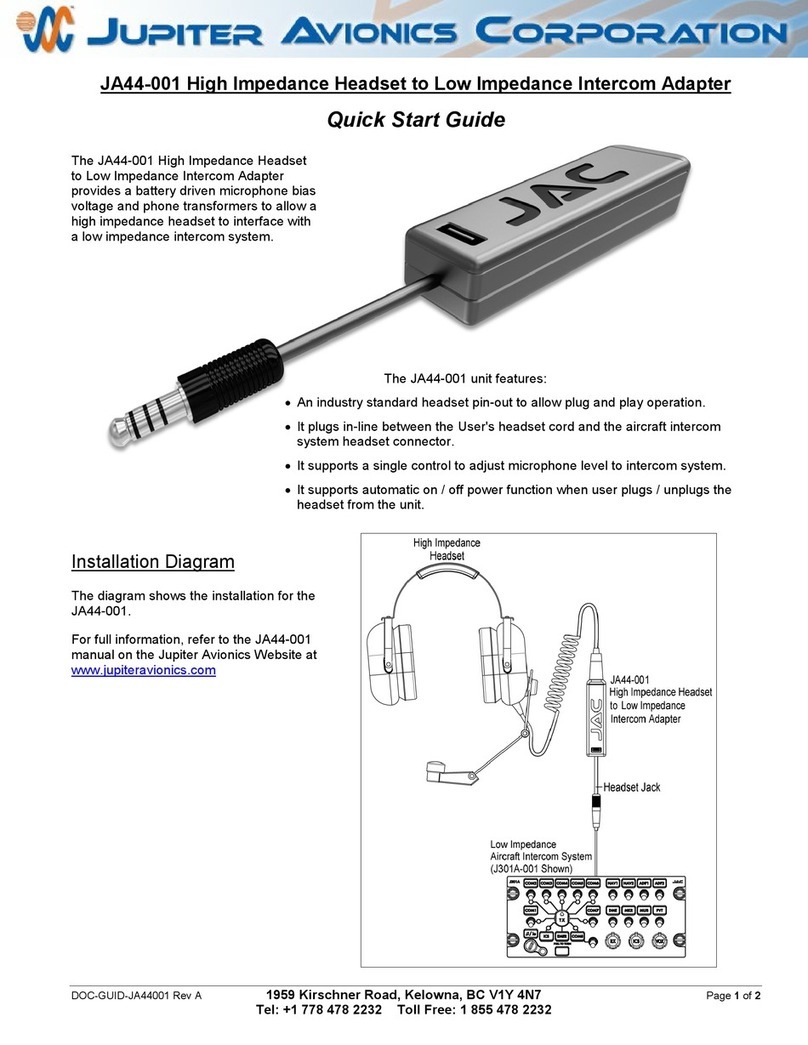
The JA44-001 High Impedance Headset to Low Impedance Intercom Adapter provides a battery driven microphone
bias voltage and phone transformers to allow a high impedance headset to interface with a low impedance intercom
system.
1.2 Features Overview
The JA44-001 unit features an industry standard headset pin-out to allow plug and play operation.
The JA44-001 plugs in-line between the User's headset cord and the aircraft intercom system headset connector.
The JA44-001 supports a single control to adjust microphone level to intercom system.
The JA44-001 supports automatic on / off power function when user plugs / unplugs the headset from the unit.
1.3 Inputs and Outputs
1.3.1 Inputs
Name
Qty
Type
MIC INPUT HI/LO
2
Audio signal
PHONES INPUT HI/LO
2
Audio signal
1.3.2 Outputs
Name
Qty
Type
MIC OUTPUT HI/LO
2
Audio signal
PHONES OUTPUT HI/LO
2
Audio signal
1.4 Specifications
1.4.1 Electrical Specifications
Power Input
MIC INPUT nominal bias voltage 8 Vdc
MIC INPUT maximum bias voltage 9.5 Vdc
MIC INPUT minimum bias voltage 7.0 Vdc
BATTERY nominal voltage 9 Vdc
BATTERY minimum voltage 7 Vdc
BATTERY input current 12 mA max

JA44-001 High Impedance Headset to Low Impedance Intercom Adapter
Installation and Operating Manual
Rev A Page 2
1.4.1.1 Audio Performance
Rated Input Level
MIC INPUT rated level 0.25 Vrms ±10%
PHONE INPUT rated level 0.9 Vrms ±10%
Rated Output Level
MIC OUTPUT rated level 250 uVrms±10%
PHONE OUTPUT rated level 4.4 Vrms±10%
Audio Frequency Response
MIC OUTPUT audio frequency response ≤3dB from 300 to 6000 Hz
PHONE OUTPUT audio frequency response ≤3dB from 300 to 6000 Hz
Distortion Characteristics
PHONE OUTPUT distortion at rated power ≤10% THD+N
PHONE OUTPUT distortion at 10% of rated power ≤3% THD+N
Input Impedance
MIC INPUT Impedance 150 Ω±10%
PHONE INPUT Impedance 5 Ω±30%
Output Load
MIC OUTPUT load Impedance 5 Ω±30%
PHONE OUTPUT load Impedance 150 Ω±10%
Audio Noise Level without Signal
Noise level below the rated output ≥60 dB
1.4.2 Mechanical Specifications
Height 1.04 in [26.4 mm] max
Length (not including connector cable) 4.95 in [125.7 mm] max
Width 1.22 in [31 mm] max
Weight 0.32 lb [0.15 kg] max
Material Black Polycarbonate Plastic
Connectors (2): J1 (Headset Plug) One U-174/U
J2 (Headset Jack) One U-92A/U
Mounting U-92A/U Jack
Bonding N/A
Installation kit part number N/A

Rev A Page 3
JA44-001 High Impedance Headset to Low Impedance Intercom Adapter
SECTION 2 – INSTALLATION
2.1 Introduction
This section contains unpacking and inspection procedures, installation information, and post-installation checks.
2.2 Continued Airworthiness
Maintenance of the JA44-001 is on condition only. Scheduled inspection and/or periodic maintenance of this unit is
not required.
2.3 Unpacking and Inspecting Equipment
Unpack the equipment carefully. Check for shipping damage and report any problems to the relevant carrier. Confirm
that the Authorized Release Certificate or Certificate of Conformance is included. Complete the on-line warranty card
from the Jupiter Avionics Corporation (JAC) website - www.jupiteravionics.com/warranty
2.3.1 Warranty
This product manufactured by JAC is warranted to be free of defects in workmanship or performance for 1 year from
the date of purchase from by an approved JAC dealer or agency. This warranty covers the cost of all materials and
labour to repair or replace the unit, but does not include the cost of transporting the defective unit to and from JAC or
its designated warranty repair centre, or of removing and replacing the defective unit in the aircraft. This warranty
does not cover failures due to abuse, misuse, accident, or unauthorized alteration or repairs.
If the on-line warranty card is not completed, the product will be warranted from the date of manufacture.
Contact JAC for return authorization, and for any questions regarding this warranty and how it applies to your unit(s).
JAC is the final arbiter concerning warranty issues.
2.4 Installation Procedures
2.4.1 Installation Limitations
The JA44-001 may be installed only by following the applicable airworthiness requirements.
2.4.2 Cabling and Wiring
The JA44-001 plugs directly into a standard aircraft audio system headset connector.
2.4.3 Mechanical Installation
The JA44-001 can be mounted in any attitude and location sufficient clearance for the connector body and headset
plug. It requires no direct cooling.
CAUTION: When plugged in to a headset audio connector, the JA44-001 could create excessive strain on
the connector. Ensure that the JA44-001 is protected from impact, and that no tension is applied to any
attached headset cord.

JA44-001 High Impedance Headset to Low Impedance Intercom Adapter
Installation and Operating Manual
Rev A Page 4
2.4.4Post Installation Checks
2.4.4.1Configuration
The JA44-001 has no configuration options.
2.4.4.2Power on Checks.
Power up the aircraft’s systems and confirm normal operation of allfunctions of the JA44-001.Refer to
Section 3 (Operation) for specific operational details.
a) Begin with a high impedance headset attached. Confirm correct operation for both Mic and phones output. Do
not proceed until the headsets are functioning correctly.
b) Unusual buzzes, hums or other background audio are symptomatic of multiple grounds, or noisy external
systems such as blowers or pumps sharing wiring with the audio system.
2.5 System Operation
The JA44-001 is designed to operate regardless of the input and output polarities of the attached audio controller and
headset.
2.5.1 Microphone Operation
The JA44-001 allows the MIC INPUT audio to be biased and decreases the audio level from the MIC INPUT to MIC
OUTPUT connectors by using a Step-down transformer.
The MIC OUTPUT audio output is adjusted though a trimpot.
2.5.2 Phones Operation
The JA44-001 increases the audio level from the PHONE INPUT to the PHONE OUTPUT connectors by using a step-
up transformer.
2.6 Installation Kit
The JA44-001 does not require an installation kit.
2.7 Installation Drawings
The drawings and documents required for Installation can be found in Appendix A of this manual.

Rev A Page 5
JA44-001 High Impedance Headset to Low Impedance Intercom Adapter
SECTION 3 – OPERATION
3.1 Introduction
This section contains the operating instructions for the JA44-001.
3.2 Controls and Connectors
The JA44-001 has an automatic on / off power function when the user plugs / unplugs the headset from the unit.
3.2.1 Mic Level Control
Underneath the battery compartment lid (see section 3.3
below) the JA44-001 has one rotary control (trimpot)
marked MIC for adjusting the Mic level.
The control is rotated using a flat blade screwdriver.
The Mic output audio will be increased when the control
is rotated clockwise (cw) and decreased when the
control is rotated counterclockwise (ccw).
U-92A/U jack (J2) to interface
with a High Impedance Headset.
U-174/U plug (J1) to interface with
a Low impedance intercom.
Battery compartment lid.

JA44-001 High Impedance Headset to Low Impedance Intercom Adapter
Installation and Operating Manual
Rev A Page 6
3.3 Battery Information
The JA44-001 uses one nine volt alkaline battery.
3.3.1 Inserting or Replacing the Battery
Retaining tabs
To replace the battery, remove the
battery cover by pressing the battery lid
release towards the JAC logo, lifting the
lower end of the cover, and then gently
prying the lid up and away from the body
to release the two tabs from the retaining
slots.
Remove the battery and insert a new
battery, matching the polarity marked on
the battery holder.
3.3.1.1 Battery Life
A good quality 9V alkaline battery at 23°C will provide typically 20+ hours of operation.
3.3.2 Battery Cautions and Warnings
CAUTION:Follow these guidelines to prolong battery life and minimize the risk of unit malfunction.
To ensure that the unit functions correctly, insert a new battery with the positive and negative poles
aligned as indicated in the battery compartment.
When replacing the battery, use only a new battery.
WARNING: Follow these guidelines to prolong battery life, and minimize the risk of fire, chemical
burns, electrolyte leaks and/or injury.
FOLLOW the manufacturer's instructions for care and disposal of batteries.
DO NOT use sharp objects to remove the battery.
DO NOT disassemble, puncture, burn or in any other way damage the battery.
DO NOT let children handle the battery.
USE ONLY recommended replacement batteries.
Battery Lid Release
Battery
Mic Level Control (MIC)

Rev A Page A1
JA44-001 High Impedance Headset to Low Impedance Intercom Adapter
Installation and Operating Manual
Appendix A - Installation Drawings
A1 Introduction
The drawings necessary for installation and troubleshooting of the JA44-001 High Impedance Headset to Low
Impedance Intercom Adapter are in this Appendix, as listed below.
A2 Installation Drawings
DOCUMENT Rev
JA44-001 Interconnect A
JA44-001 Mechanical Installation A

JUPITER AVIONICS TEMPLATE AUTOCAD PORTRAIT SIZEA REV B.DWT
TITLE
APPROVED
PREPARED
CHECKED
L00N3
NCAGE CODE PART NO. SHEET
DOC NO.
CONFIDENTIAL & PROPRIETARY
TO JUPITER AVIONICS CORP.
High Impedance Headset to
Low Impedance Intercom Adapter
JA44-001 1/1
JA44-001 Interconnect Rev A.dwg
TAT
Aircraft Intercom System
(J301A-001 Shown)
High Impedance Headset to
Headset
JA44-001
Headset Jack
Low Impedance
Low Impedance Intercom Adapter
High Impedance
JAC
TAT
10-24-18
JAC
KDV
10-24-18

0in
0mm
4.95in
125.7mm
9.25in MAX
235.0mm MAX
0in
0mm
0in
0mm
1.22in
31mm
1.04in
26.4mm
J1
TEXTORIENTATIONTHISWAY
NCAGE CODE
L00N3
FINISH:
MATERIAL: N/A
N/A
PART NO.
PREPARED TAT
JA44-001
CHECKED
APPROVED SHEET
TO JUPITER AVIONICS CORP.
High Impedance Headset to Low Impedance
1/1
0.5 DEG
TITLE
JUPITER AVIONICS TEMPLATE SOLIDWORKS PORTRAIT SIZEB REV B.DRWDOT
Intercom Adapter
JA44-001 Mechanical installation Rev A.SLDDRW
DOC. NO.
UNLESS OTHERWISE SPECIFIED
DIMENSIONS ARE IN INCHES
ANGLES ARE IN DEGREES
TOLERANCES:
1 DEC PLACE: 0.1
2 DEC PLACE: 0.01
3 DEC PLACE: 0.005
ANGLES:
CONFIDENTIAL & PROPRIETARY
DRAWING NOT TO SCALE
J2
Notes:
All dimensions 0.02in [0.5mm] unless otherwise specified.1. Weight: 0.32 lbs [0.15 Kg] MAX. with batteries.2.
JAC
TAT
10-24-18
JAC
KDV
10-24-18

Rev A Page B1
JA44-001 High Impedance Headset to Low Impedance Intercom Adapter
Installation and Operating Manual
Appendix B - Installation Documents

JA44-001 High Impedance Headset to Low Impedance Intercom Adapter
Installation and Operating Manual
Rev A Page B2
B1 Airworthiness Approval
Airworthiness approval of the JA44-001 may require completion of a TCCA Major Modification Report per CAR STD
(AWM) 571 Appendix L, or a FAA Form 337. The sample wording for a description of the work is provided to assist
the Installing Agency in preparing Instructions for Continued Airworthiness (ICA) when replacing an existing audio
panel with a Jupiter Avionics JA44-001 High Impedance Headset to Low Impedance Intercom Adapter. This sample
may be modified appropriately for new installations. It is the installer’s responsibility to determine the applicability of
the method used. Installations performed outside Canada must follow the applicable aviation authority’s regulations.
Sample Wording:
Removed the existing [model] audio panel and replaced with a Jupiter Avionics JA44-001 High Impedance Headset to
Low Impedance Intercom Adapter in [aircraft location].
See Section 1 of the JA44-001 Installation Manual.
Installed in accordance with the JA44-001 Installation Manual, Revision [ ], and AC 43.13-2, Chapters 2, and 3.
The JA44-001 interfaces with existing aircraft systems per the Installation Manual instructions.
The JA44-001 Installation Manual provides detailed installation instructions and wiring diagrams (Section 2, and
Appendices A and B).
Power is supplied to the JA44-001 through an existing [ ]-Amp circuit breaker that was previously used by the original
audio panel. The net electrical load is unchanged.
Aircraft equipment list, weights and balance amended. Compass compensation checked and found to conform to
applicable regulations.
B2 Instructions for Continued Airworthiness
Maintenance of the JA44-001 High Impedance Headset to Low Impedance Intercom Adapter is “on condition” only.
Refer to the JA44-001 Maintenance Manual. Periodic maintenance of the JA44-001 is not required.
The following sample Instructions for Continued Airworthiness (ICA) provides assistance in preparing ICA for the
Jupiter Avionics JA44-001 unit installation as part of a Type Certificate (TC) or Supplemental Type Certificate (STC)
project to comply with CAR STD (AWM) 523/527/525/529.1529 or FAR 23/25/27/29.1529 “Instructions for Continued
Airworthiness”.
Items that may vary by aircraft make and model are shown in brackets (“[ ]”) and should be filled in as appropriate.
Some of the checklist items do not apply, in which case they should be marked “N/A” (Not Applicable).
Instructions for Continued Airworthiness, Jupiter Avionics JA44-001 High
Impedance Headset to Low Impedance Intercom Adapter in an [Aircraft Make
and Model]
1. Introduction
[Aircraft that has been altered: Registration number, Make, Model and Serial Number]
Content, Scope, Purpose and Arrangement: This document identifies the Instructions for Continued
Airworthiness for a Jupiter Avionics JA44-001 installed in an [aircraft make and model].
Applicability: Applies to a Jupiter Avionics JA44-001 installed in an [aircraft make and model].
Definitions/Abbreviations: None, N/A.
Precautions: None, N/A.
Units of Measurement: None, N/A.
Referenced Publications: JA44-001 Installation and Operating Manual
JA44-001Maintenance Manual
STC/TC # [applicable STC/TC number for the specific aircraft installation]
Distribution: This document should be a permanent aircraft record.

JA44-001 High Impedance Headset to Low Impedance Intercom Adapter
Installation and Operating Manual
Rev A Page B3
2. Description of the System/Alteration
Jupiter Avionics JA44-001 High Impedance Headset to Low Impedance Intercom Adapter with interface to
external transceivers and [include other equipment/systems as appropriate]. Refer to Appendix A of this manual
for interconnect information. Refer to aircraft manufacturer approved interconnect for actual installation.
3. Control, Operation Information
Refer to section 3 of this manual.
4. Servicing Information
N/A
5. Maintenance Instructions
Maintenance of the JA44-001 is ‘on condition’ only. Periodic maintenance is not required. Refer to the
JA44-001Maintenance Manual.
6. Troubleshooting Information
Refer to the JA44-001 Maintenance Manual.
7. Removal and Replacement Information
Refer to Section 2 of this manual - the JA44-001 Installation and Operating Manual. If the unit is removed and
reinstalled, a functional check of the equipment should be conducted.
8. Diagrams
Refer to Appendix A of this manual - the JA44-001 Installation and Operating Manual - for installation drawings
and interconnect examples.
9. Special Inspection Requirements
N/A
10. Application of Protective Treatments
N/A
11. Data: Relative to Structural Fasteners
JA44-001 and appropriate mounting hardware installation, removal and replacement should be in accordance
with applicable provisions of AC 43.13-1B and AC 43.13-2A.
12. Special Tools
N/A
13. This Section is for Commuter Category Aircraft Only
A. Electrical loads: Refer to Section 1 of the JA44-001 Installation and Operating Manual.
B. Methods of balancing flight controls: N/A.
C. Identification of primary and secondary structures: N/A.
D. Special repair methods applicable to the airplane: N/A.
14. Overhaul Period
No additional overhaul time limitations.
15. Airworthiness Limitation Section
N/A
Other manuals for JA44-001
1
Table of contents
Other Jupiter Avionics Adapter manuals

Jupiter Avionics
Jupiter Avionics JB39-401 User manual

Jupiter Avionics
Jupiter Avionics JA39-022 User manual

Jupiter Avionics
Jupiter Avionics JA39-075 User manual

Jupiter Avionics
Jupiter Avionics JA44-001 User manual

Jupiter Avionics
Jupiter Avionics JA34-001 User manual

Jupiter Avionics
Jupiter Avionics JA34-BT1 User manual
Popular Adapter manuals by other brands

ZyXEL Communications
ZyXEL Communications ZyXEL ZyAIR B-220 user guide

Cables Unlimited
Cables Unlimited 925-609-7550 reference guide

Inateck
Inateck UA1001 instruction manual

Linksys
Linksys WUSB11 ver. 2.6 user guide

Thermaltake
Thermaltake ADP65W0001 user guide

Micro Innovations
Micro Innovations USB50BT Quick installation guide