Jupiter Avionics JA70-005 User manual

JA70-005 Five Dzus Glove Box
Installation Manual
Rev A Page ii
Copyright 2013 Jupiter Avionics Corp.
All rights reserved
Jupiter Avionics Corporation (JAC) permits a single copy of this manual to be printed or downloaded for the express
use of an installing agency. Any such electronic or printed copy of this manual must contain the complete text of this
copyright notice. Any unauthorized commercial distribution of this manual is strictly prohibited. Except as described
above, no part of this manual may be reproduced, copied, transmitted, disseminated, downloaded, or stored in any
storage medium for any purpose without the express prior written consent of JAC.
RECORD OF REVISIONS
Revision
Rev Date
Description
ECR
A
Nov 2013
Initial release, Serial number 1001 and higher.
1744
Prepared:
MPB
Checked:
Approved:
IMPORTANT:
Information in this document is subject to change without notice.
To confirm the current revision status of this manual, visit the JAC website:
www.jupiteravionics.com
JAC
SRM
12-06-13 JAC
KDV
12-06-13

JA70-005 Five Dzus Glove Box
Installation Manual
Rev A Page iii
Table of Contents
SECTION 1 - DESCRIPTION...........................................................................................................................................1
1.1 System Overview..............................................................................................................................................1
1.2 Features Overview............................................................................................................................................1
1.4 Specifications....................................................................................................................................................1
1.4.1 Mechanical Specifications ........................................................................................................................1
1.4.2 Environmental Specifications....................................................................................................................1
1.4.3 Flammability of Materials..........................................................................................................................1
SECTION 2 – INSTALLATION........................................................................................................................................2
2.1 Introduction.......................................................................................................................................................2
2.2 Continued Airworthiness...................................................................................................................................2
2.3 Unpacking and Inspecting Equipment..............................................................................................................2
2.3.1 Warranty .......................................................................................................................................................2
2.4 Installation Procedures.....................................................................................................................................2
2.4.1 Mechanical Installation .................................................................................................................................2
2.5 Installation Kit ...................................................................................................................................................2
2.6 Installation Drawings.........................................................................................................................................2
Appendix A - Installation Drawings........................................................................................................................... A1
A1 Installation Drawings.......................................................................................................................................A1

Rev A Page 1
JA70-005 Five Dzus Glove Box
SECTION 1 - DESCRIPTION
1.1 System Overview
The JA70-005 Dzus Glove Box allows the aircraft owner/operator to utilise an unused portion of the instrument panel
for temporary storage. The interior of the glove box has a soft, high friction finish to minimize noise and movement
due to vibration.
1.2 Features Overview
The JA70 has a black anodized finish to resist scratches and nicks during use.
1.3 Specifications
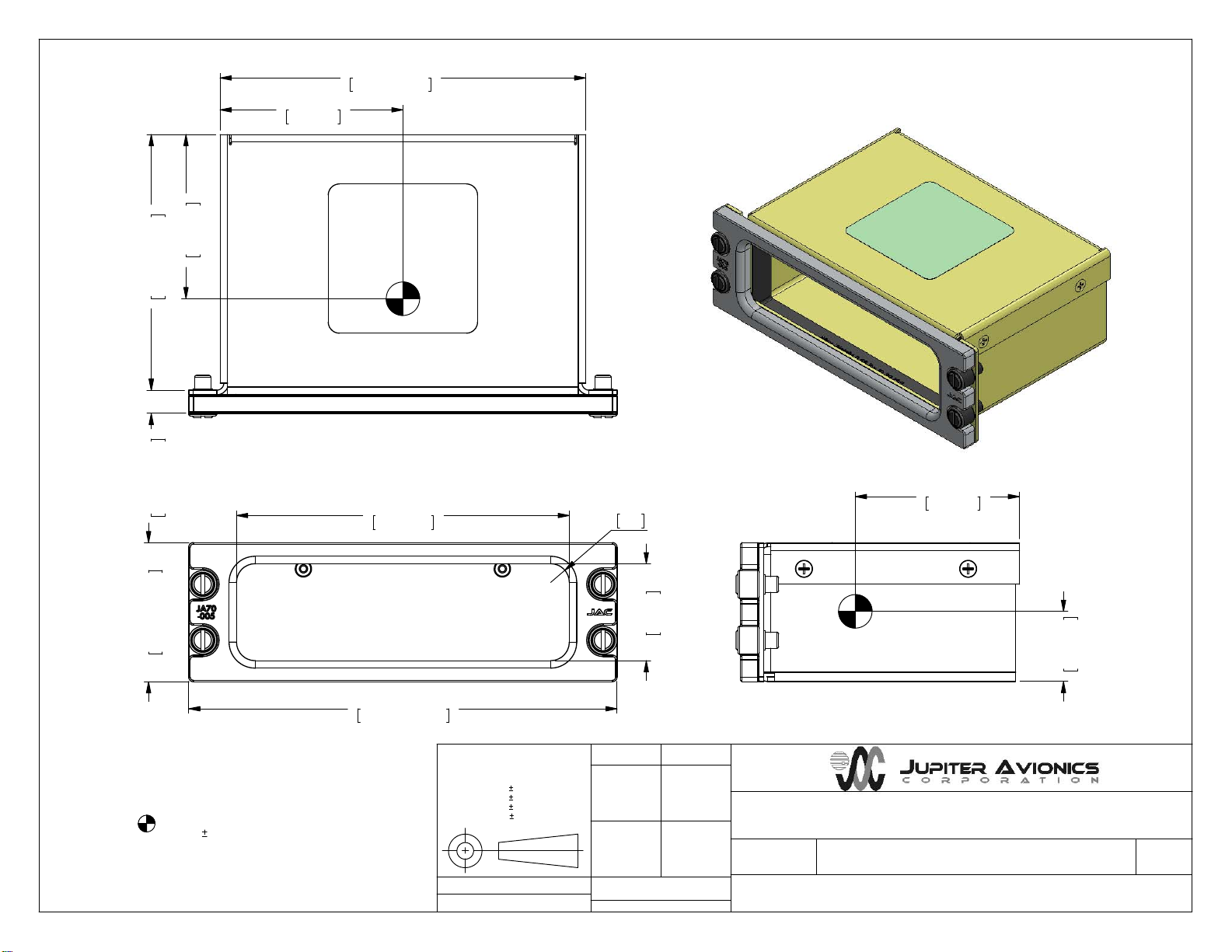
1.3.1 Mechanical Specifications
Refer to Mechanical Installation drawing for all dimensions
Height 1.875 in [47.62 mm] maximum
Depth behind panel 3.45 in [87.6 mm] maximum
Depth of panel 0.33 in [8.13 mm] maximum
Width 5.75 in [146.1 mm] maximum
Weight 0.52 lb [0.236 kg] maximum
Material Black anodized 5052-H32 aluminum
Mounting 4 Dzus fasteners
Load 0.66 lb [0.30 kg] maximum
Installation kit part number N/A
1.3.2 Environmental Specifications
The JA70-005 Dzus Glove Box has been qualified to the environmental conditions listed below.
Operational Shock and Crash Safety
Operational Shock
Crash Safety (impulse)
Crash Safety (sustained)
7.0
7.2.1
7.3.1
7.3.3
Equipment tested to DO-160G Cat. B (6 g for 11 ms)
Equipment tested to DO-160G Cat. B (20 g for 11 ms)
Equipment tested to DO-160G Cat. B (20 g for 3 sec)
Vibration
Fixed Wing - Sine
Fixed Wing - Random
Helicopter - Random, unknown
8.0
8.5.1
8.5.2
8.8.3
Equipment tested to DO-160G Cat. SM
Equipment tested to DO-160G Cat. SB
Equipment tested to DO-160G Cat. U2FF1
1.3.3 Flammability of Materials
The JA70-005 complies with the requirements of RTCA/DO-160G Sec 26.3.3 Cat. C "Flammability", through
equivalent flammability testing of materials.

Rev A Page 2
JA70-005 Five Dzus Glove Box
SECTION 2 – INSTALLATION
2.1 Introduction
This section contains unpacking and inspection procedures, installation information, and post-installation checks.
2.2 Continued Airworthiness
Maintenance of the JA70-005 is on condition only. Scheduled inspection and/or periodic maintenance of this unit is
not required.
2.3 Unpacking and Inspecting Equipment
Unpack the equipment carefully. Check for shipping damage and report any problems to the relevant carrier. Confirm
that the Authorized Release Certificate or Certificate of Conformance is included. Complete the on-line warranty card
from the Jupiter Avionics Corporation (JAC) website – www.jupiteravionics.com/warranty.
2.3.1 Warranty
All products manufactured by JAC are warranted to be free of defects in workmanship or performance for 2 years
from the date of installation by an approved JAC dealer or agency. This warranty covers the cost of all materials and
labour to repair or replace the unit, but does not include the cost of transporting the defective unit to and from JAC or
its designated warranty repair centre, or of removing and replacing the defective unit in the aircraft. This warranty
does not cover failures due to abuse, misuse, accident, or unauthorized alteration or repairs.
Contact JAC for return authorization, and for any questions regarding this warranty and how it applies to your unit(s).
JAC is the final arbiter concerning warranty issues.
2.4 Installation Procedures
2.4.1 Mechanical Installation
The JA70-005 can be mounted in any attitude and location with adequate space.
2.5 Installation Kit
N/A
2.6 Installation Drawings
The drawings and documents required for Installation can be found in Appendix A of this manual.

Rev A Page A1
JA70-005 Five Dzus Glove Box
Installation Manual
Appendix A - Installation Drawings
A1 Installation Drawings
DOCUMENT Rev
JA70-005 Mechanical Installation B

0.03in [0.8mm]
CENTER OF GRAVITY
WEIGHT: 0.52 lbs [0.236 kg] MAX.
2.20in
55.9mm
0.94in
23.9mm
2.45in
62.2mm
2.20in
55.9mm
CONFIDENTIAL & PROPRIETARY
JUPITER AVIONICS TEMPLATE SOLIDWORKS LANDSCAPE SIZEA REV B.DRWDOT
Five Dzus - Glove Box
JA70-005 Mechanical Installation Rev B.SLDDRW
DOC. NO.
1/1
SHEET
JA70-005
PART NO.
TITLE
DRAWING NOT TO SCALE
TO JUPITER AVIONICS CORP.
APPROVED
CHECKED
TATPREPARED
N/A
N/A
MATERIAL:
FINISH:
NCAGE CODE
L00N3
UNLESS OTHERWISE SPECIFIED
DIMENSIONS ARE IN INCHES
ANGLES ARE IN DEGREES
TOLERANCES:
1 DEC PLACE: 0.1
2 DEC PLACE: 0.01
3 DEC PLACE: 0.005
ANGLES: 0.5 DEG
1.875in MAX
47.6mm MAX
4.46in
113.3mm
33mm
146.1mm MAX
5.75in MAX
1.30in
R0.25
6.4
8.4mm MAX
0.33in MAX 3.45in MAX
87.6mm MAX
5.00in MAX
127mm MAX
Table of contents
Other Jupiter Avionics Storage manuals
Popular Storage manuals by other brands

Kingston Technology
Kingston Technology DataTraveler Locker+ Generation 3 DTLPG3 installation guide

HP
HP P2000 G3 installation instructions

American Megatrends
American Megatrends StorTrends 2401 Setup guide

AA Products
AA Products SH-4603-GAP instruction manual

Seagate
Seagate SKYHAWK ST4000VX005 product manual

LG
LG ESS Home 10 owner's manual

LogiLink
LogiLink NS0045A user manual

Maxtor
Maxtor C01W015 - Maxtor OneTouch III Turbo Edition Hard Drive... quick start guide

NETGEAR
NETGEAR MA701 - 802.11b 11 Mbps Compact Flash Card user guide

ACP-EP Memory
ACP-EP Memory CISURF-MBM/2G brochure

Buffalo
Buffalo HDW-PDU3 MiniStation Air Specifications

Hitachi
Hitachi Ultrastar 15K300 Quick installation guide