Jupiter Instruments_____________________________________________________________________________________
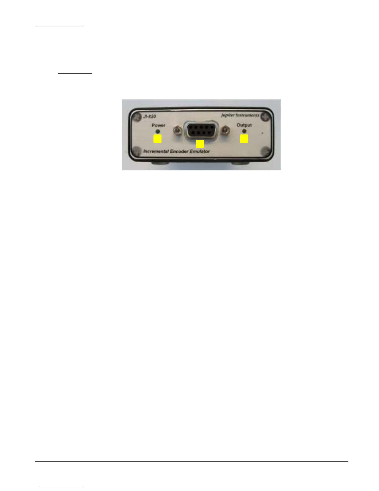
JI-820
4
2/18/18
1. INTRODUCTION
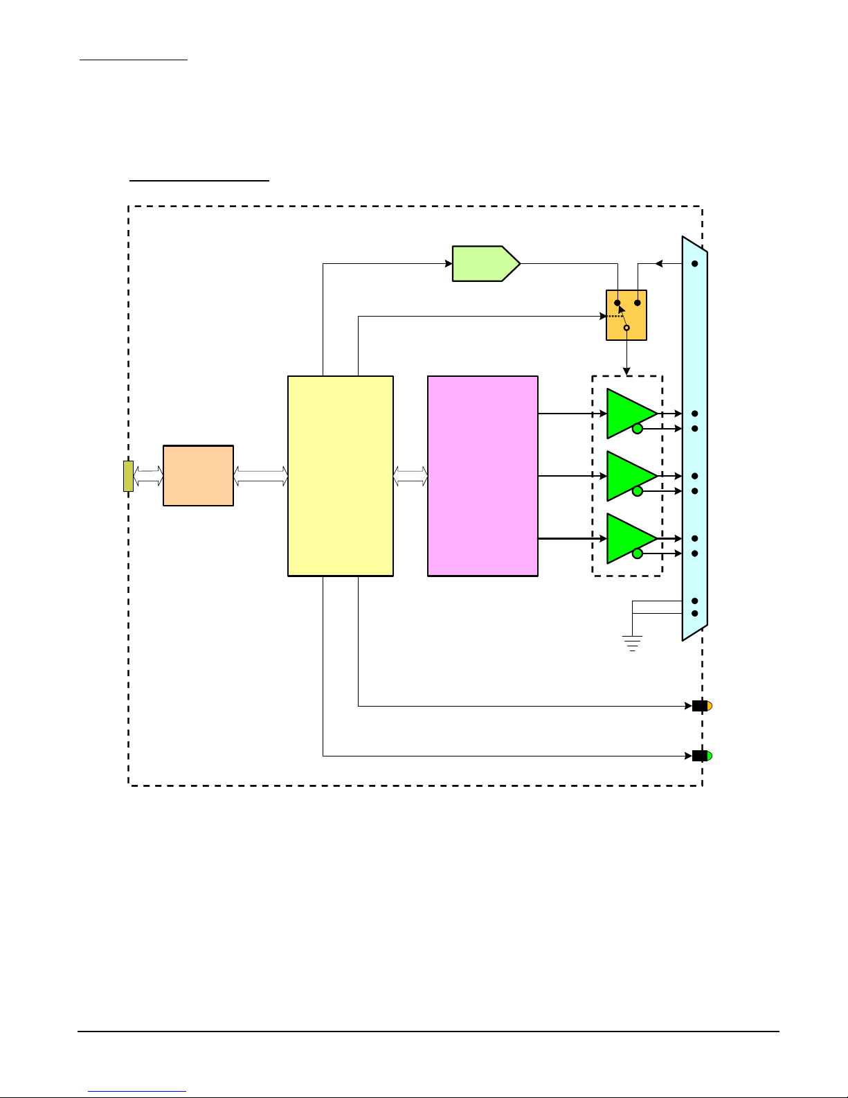
The JI-820 is a flexible, easy-to-use, PC cont olled inst ument designed to p ecisely emulate the
function of a wide va iety of inc emental encode s. It p ovides the design, system, o test enginee
with a tool to accu ately emulate encode signals gene ated by motion cont ol and indust ial
monito ing systems. Va iable encode pa amete available to the use include cycles pe evolution,
cycle f equency, A/B signal phase, Z signal position and pola ity, signal amplitude, and selectable
signal inte face. An intuitive Windows application manages inst ument setup and cont ol.
Communications and unit powe is all p ovided via a USB 2.0 connection.
eatures
• Emulates/Simulates Rota y, Linea , and Quad atu e Encode s
• P og ammable Pulse-Pe -Rev: 4 to 4,000,000
• Adjustable Cycle F equency: 0.1 Hz to 5.0 MHz (50 nS steps)
• Va iable A/B Phase: 10° to 170° in 1° steps (90° nominal)
• Index (Z) Signal: Selectable Pola ity (+/- pulse) and Position (+/- 1 cycle)
• Va iable Signal (A, B, Z) Amplitude: Inte nal - 5.0 to 18.0 Volts (100 mV steps)
Exte nal - 5.0 to 30.0 Volts
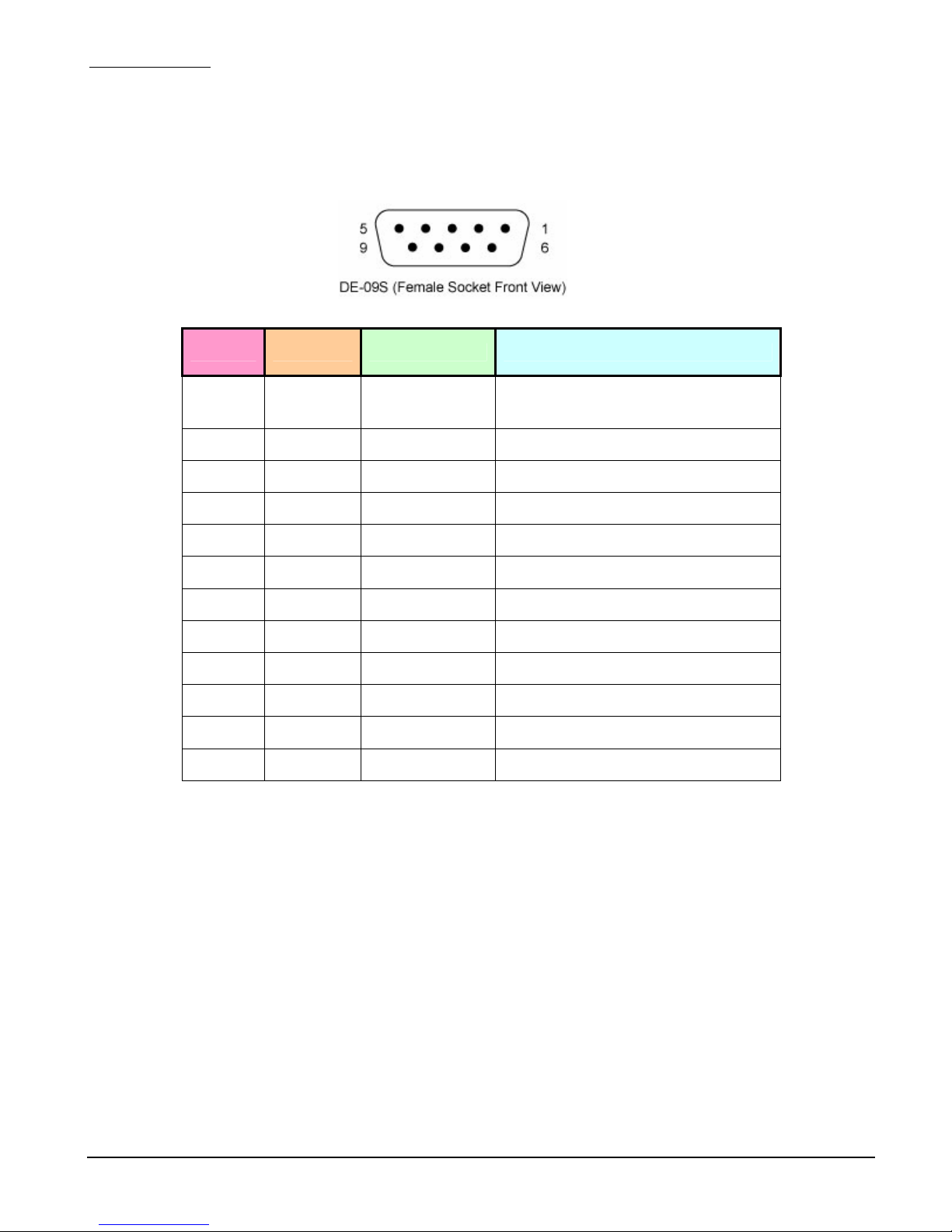
• Output Inte face: RS-422, Open-D ain, Push-Pull, o Push-Pull Complementa y
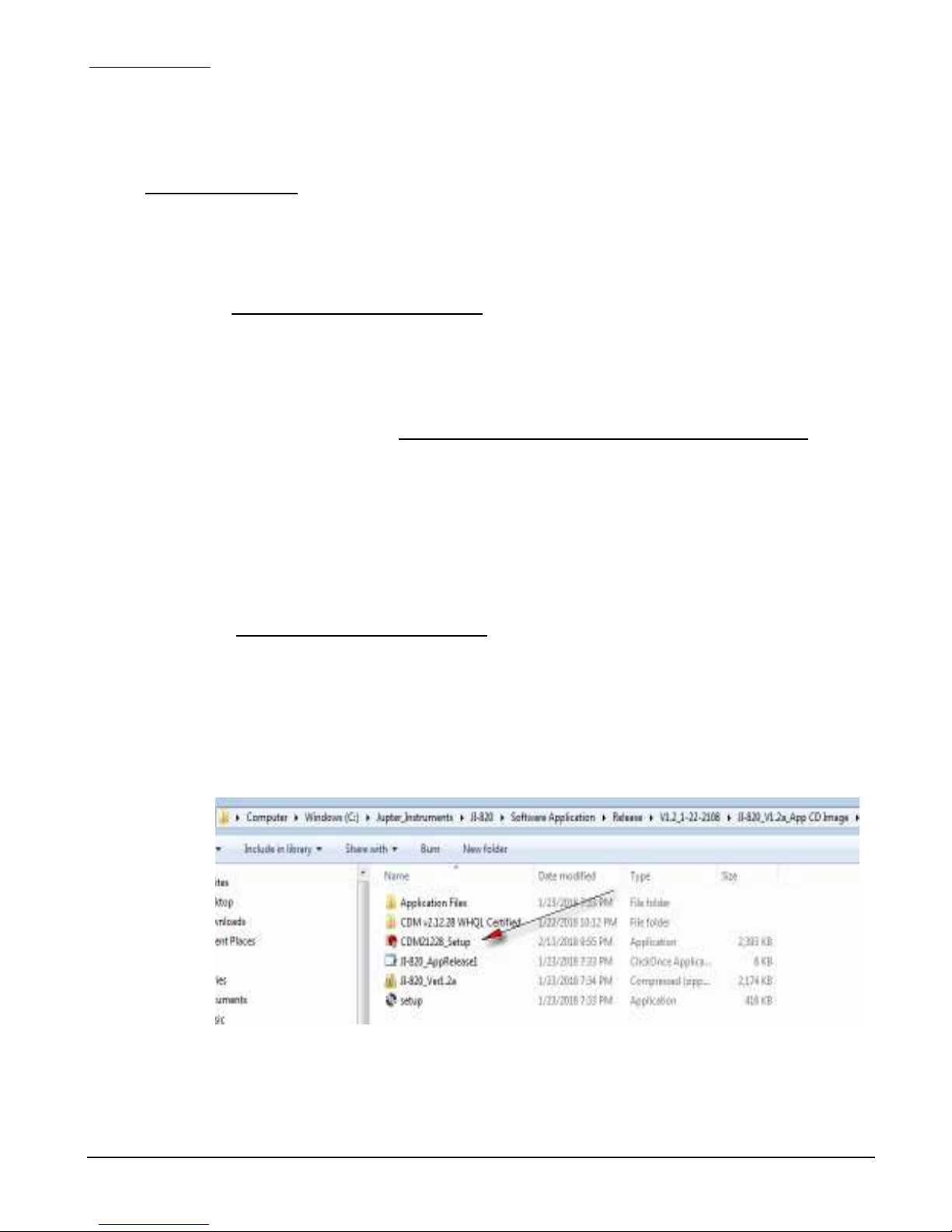
• Inst ument Setup and Cont ol via an intuitive Windows Application GUI
• Unit powe and communications via USB 2.0. No exte nal powe -supply equi ed.