Juxta VJQ7 User manual

User’s
Manual
Model VJQ7
Analog to Pulse Converter (Multi-function)
(Isolated Single-output and Isolated Dual-output Types)
IM 77J01Q17-01E
IM 77J01Q17-01E
1st Edition Feb. 2000
4th Edition Mar. 2016
CAUTIONARY NOTES FOR SAFE USE OF
THE PRODUCT
This User’s Manual should be carefully read before installing
and operating the product. Please keep this User’s Manual
for future reference.
The following symbol is used on the product and in this
manual to ensure safe usage.
This symbol is displayed on the product when
it is necessary to refer to the User’s Manual for
information on personal and instrument safety.
This symbol is displayed in the User’s Manual
to indicate precautions to avoid danger to the
operator, such as an electric shock.
The following symbols are used only in this manual.
NOTE
Draws attention to essential information for
understanding the operations and/or functions of
the product.
CHECKING PRODUCT SPECIFICATIONS
AND THE CONTENTS OF PACKING
(1)ModelNumberandSpecicationCheck
Checkthatthemodelnumberandspecicationsshown
on the nameplate attached on the side of the product are
as ordered.
(2)ContentsofthePacking
Checkthatthepackingcontainsthefollowingitems:
• VJQ7:1unit
• Tag number label, 1 sheet
• Rangelabel:1sheet
• Shuntregistor(forspecicationofcurrentinput),1
piece
• User'sManual(thismanual):1copy
GENERAL
The VJQ7 is a plug-in analog/pulse Transmitter that converts
DCcurrentorDCvoltagesignalintoisolatedtransistor-
contactpulseorcontactlessACswitchpulse.
TheVJQ7converterfeatures:
• Either pulse output, communication function (RS-485), or
alarm output (2 relay contacts) is selectable as Output-2.
• Various parameters such as input range can be set and
modiedusingaPC(VJ77(soldseparately))orHandy
Terminal(JHT200(soldseparately)andthelike).
MODEL AND SUFFIX CODES
Model Sufx codes Description
VJQ7 -0 □ □ -□ □ □ 0/□ AnalogtoPulseConverter
(Multi-function)
-0 Always -0
Output
conguration
11 output
22 outputs
Power supply 6100-240VAC/DC*1
715-30VDC*2
Input signal
-A 0to50mADC,spanis
5mA or more
-1 –10to+10VDC,spanis
0.1V or more
Output-1 signal 1Open collector
3ContactlessACswitch
Output-2 signal
1Open collector
3ContactlessACswitch
PCommunicationfunction
(RS485)
TAlarm output (2 relay
contacts)
NNo Output-2
0Always 0
Option Blank:Withsocket
/SN Withoutsocket
*1:Operatingrange:85to264V
*2:Operatingrange:12to36V
1. MOUNTING METHODS
Note
Insert/pull out the main unit into/from the socket
vertically to the face of socket. Otherwise the
terminals are bent and it may cause a bad contact.
1.1 Wall Mounting
Loosenthemainunit-xingscrewofthetransmitterto
disconnectthemainunitfromthesocket.Next,anchorthe
socket onto the wall with screws. Then, plug the main unit
into the socket and secure the main unit with the main unit-
xingscrew.
29.5 or more
22±0.2
2-M4 or
2-ø
4.5 or more
Mounting Dimensions
Unit: mm
59±0.3
Main unit-fixing screw
Socket
Main unit
Threaded hole for
fixing the main unit
Mounting screws
Keep this manual in a safe place.
2-9-32, Naka-cho Musashino-shi, Tokyo 180-8750 Japan
Phone: +81-422-52-7179 Facsimile: +81-422-52-6793
http://www.yokogawa.com/ns/juxta/im/
You can download the latest manuals from the following website:
ThankyouforpurchasingtheJUXTASignalConditioner.Pleasereadthroughthismanualbeforeuseforcorrecthandling.

2
IM 77J01Q17-01E 4th Edition Mar.14,2016-00
1.2 DIN Rail Mounting
LocatethetransmittersothattheDINrailtsintotheupper
part of the DIN-rail groove at the rear of the socket, and
fasten the socket using the slide lock at the lower part of the
socket.
DIN rail
DIN rail
(Rear of socket)
Slide lock
DIN rail
Fit into here
Push
1.3 Mounting Using a Multi-mounting Base
For mounting using a multi-mounting base, see the
InstructionManualforVJCE(VJMountingBase).
1.4 Using Ducts
Wiringductsshouldbeinstalledatleast30mmawayfrom
the top or bottom of the main unit.
2. INSTALLATION LOCATION
• For installation, avoid any location where the product
may be subject to vibrations, corrosive gases, or large
amountsofdust,orwheretheproductisexposedto
water, oil, solvents, direct sunlight, radioactive rays, or
strongelectricormagneticelds.
• If there is a possibility that lightning could induce a high
surge voltage on the power and signal lines, provide
lightningarrestersonthelinebetweentheeldinstrument
and indoor instrument in order to protect the product.
Installadedicatedarresterontheeldsideandanother
on the indoor side.
• Operatingtemperature/humidityrange:0to50°C/5to
90%RH(nocondensation)
3. EXTERNAL WIRING
WARNING
To avoid the risk of an electric shock, turn off the
power supply and use a tester or similar device to
ensure that no power is supplied to a cable to be
connected, before carring out wiring work.
Wiringshouldbeconnectedtotheterminalsonthesocket
oftheproduct.Theterminalsforexternalconnectionsareof
M3 screws. Use crimp-on terminal lugs for connections to
the terminals.
Note
When power of VJQ7 is turned on/off, one pulse
may be counted by the pulse input device which
connects to the VJQ7.
• Recommendedcables:Anominalcross-sectionalareaof
0.5 mm2 or thicker for signal cables, and that of 1.25 mm2
or thicker for power cables.
Pulse
output
Output-1 signal
Pulse output
Output-2 signal
Alarm output
RS-485
communication
Input
R: Externally connected
for current input
Shunt resistor
(Externally connected
for current input)
1011
3 2 1
56
789
1110 8
L+N–GND
1
3
+
–
+
–
+
R
–5
2
6
5
2
9
7
ALM1
(N.O.)
(N.O.)
ALM2
COM 5
2
6
B+
A–
COM
NOTE
●Do not use output-2 for the single-output type.
●The power line and input/output signal lines
should be installed away from noise-generating
sources. Other wise accuracy cannot be
guaranteed.
●Make sure to earth ground the ground terminal
through minimum resistance. The length and
thickness of the grounding cable should be as
short and thick as possible. Directly connect
the lead from the ground terminal (terminal no.
8) of the product to the ground. Do not carry
out daisy-chained inter-ground terminal wiring.
●Use of the product ignoring the specications
may cause overheating or damage. Before
turning on the power, ensure the following:
• Power supply voltage and input signal value
applied to the product should meet the required
specications.
• Theexternalwiringtotheterminalsandwiringto
groundareasspecications.
●Do not operate the product in the presence of
ammable or explosive gases or vapors. To do
so is highly dangerous.
●The product is sensitive to static electricity;
exercise care in operating it. Before you
operate the product, touch a nearby metal part
to discharge static electricity.
●If an inductance (L) load such as auxiliary
relays or solenoid valves is used, always insert
a spark killer for diminishing sparks, such
as a CR lter or a diode in parallel with the
inductance load. Otherwise a malfunction or
relay failure may occur. Refer to the following
guidelines for a capacitor and resistor:
Capacitor : 0.5 to 1 µF with respect to a contact
current of 1 A
Resistor: 0.5 to 1 Ωwith respect to a contact
voltage of 1 V
●For 15-30 V DC (±20%) power supply, as a
safety measure, always install a circuit breaker
(an IEC 60947-compatible product, 1 A, 30 V
DC) in an easily accessible location near the
instrument. Moreover, provide indication that
the switch is a device for turning off the power
to the instrument.

3
IM 77J01Q17-01E 4th Edition Mar.14,2016-00
4. DESCRIPTION OF FRONT PANEL AND
CONNECTION OF SETTING TOOLS
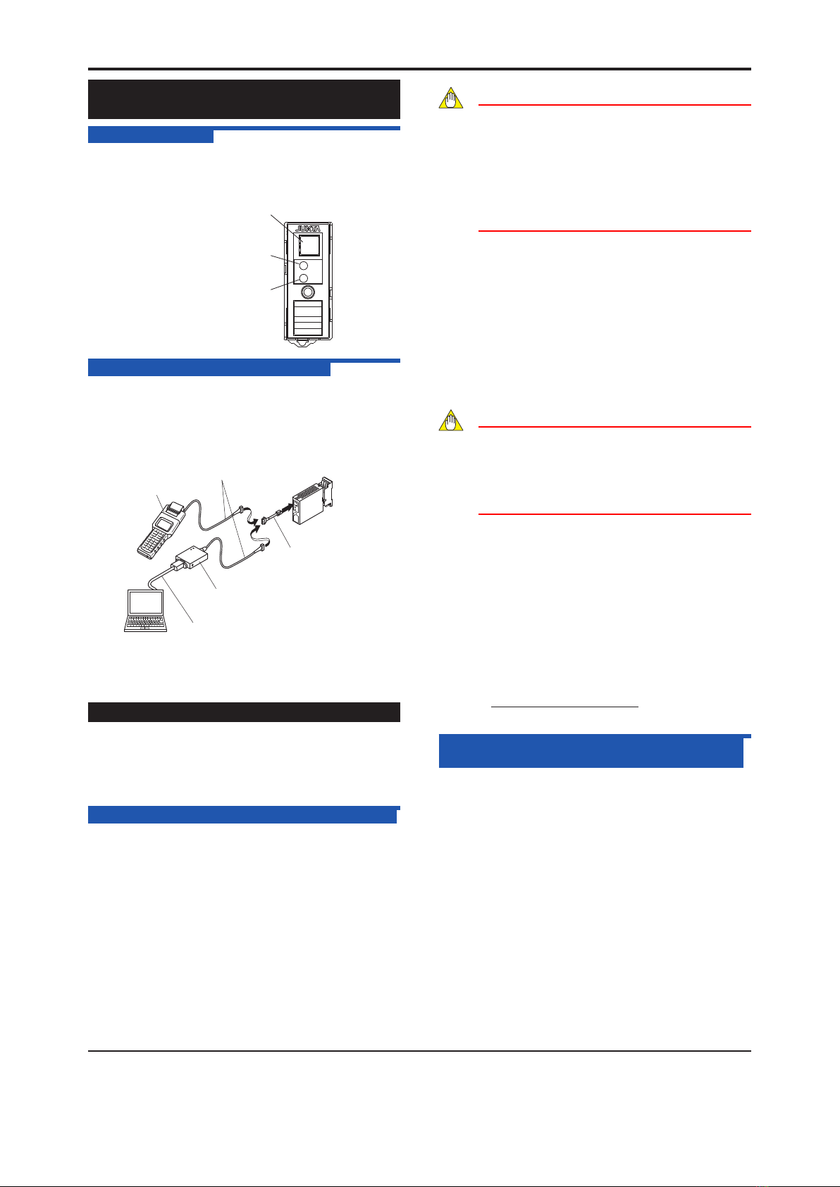
4.1 Front Panel
The communications connector in the front panel is used
forsettingupparametersthroughaPC(VJ77PC-based
ParametersSettingTool)ortheHandyTerminal.TheALM1
and ALM2 LEDs light up if an alarm occus (those LEDs are
providedonlywhentheoutput-2isspeciedforalarmoutput.)
ALM 1
ALM 2
Alarm output-1 LED
(lights up if an alarm occurs)
Communications connector
Alarm output-2 LED
(lights up if an alarm occurs)
4.2 Connecting the Setting Tools
Connectthemodularjack-to-connectoradapter(E9786WH)
to the JUXTA communication cable with 5-pin connector
(F9182EE) and then connect this adapter to the
communication connector of JUXTA.
< How to connect with the setting tool>
JHT200
Handy Terminal
JUXTA communication cable with
5-pin connectors (F9182EE)
[Provided with VJ77, JHT200]
Modular jack conversion
adapter (E9786WH)
[Provided with VJ77]
Dedicated adapter (E9789HA)
[Provided with VJ77]
Dedicated cable (E9786WK)
[Provided with VJ77]
PC
• Use the VJ77 of version R1.04 or later.
• The modular jack conversion adapter does not come with
theJHT200HandyTerminal.Itissoldseparately.
5. SETTING PARAMETERS
SettheparametersusingaPC(VJ77ParameterSetting
Tool)ortheHandyTerminal.Referto“7. LIST OF
PARAMETERS” in this manual and the User’s Manual for
VJ77PC-basedParametersSettingTool(IM77J01J77-
01E)ortheUser’sManualforJHT200HandyTerminal(IM
77J50H01-01EN).
5.1 Settings Related to Inputs and Outputs
5.1.1 Input Type
SetbyselectinginputtypefromamongVOLTS(DC
voltage)andCURRENT(DCcurrent)inD16:INPTYPE.
5.1.2 Input Hard Range
Set by selecting the input hard range from among AUTO,
HIGH,MIDDLE,andLOWinD17:SELECTRANGE.
Generally,selectAUTO.
• AUTO:Setstheinputhardrangeautomaticallywith
respect to the input range to be set.
• HIGH:Foraspanof5Vormoreinaninputrangeof-10to+10V
• MIDDLE:Foraspanof2.5Vormoreinaninput
range of -5 to +5 V
• LOW:Foraspanof0.5Vormoreinaninputrangeof-1to+1V
For the current input, convert the current range within
0-50mADCtothevoltagerange(inputrangexinput
resistor), and apply the condition mentioned above.
NOTE
The conditions for the input hard range (HIGH,
MIDDLE, and LOW) are specied for operations
within the range of accuracy rating. The input
range may be set to a range not meeting these
conditions, but take note of accuracy limitations.
Similar accuracy limitations exist even when AUTO
is selected. For more information on accuracy
limitations, see the general specications of VJQ7
(GS 77J1Q17-01E).
5.1.3 Input Range
Setthe0%valueofinputrangetoD22:INPUT1
L_RANGEandthe100%valueofinputrangetoD23:
INPUT1H_RANGEwithinthenumericallyspeciedrange.
5.1.4 Output Range Unit
Whenreferringandsettingtheoutputrange,selectand
setHzorkHzinD10:UNIT.
5.1.5 Output Range
Setthe0%valueofoutputrangeinD24:OUTL_RNG,
and100%ofoutputrangeinD25:OUTH_RNGwithin
thenumericallyspeciedrange.
Note
In case the input and output range is changed
after factory-ship, the instrument may not work
within the rated accuracy range depending on
the changed input range. Perform the adjustment
following the maintenance of this instruction
manual after changing the input range.
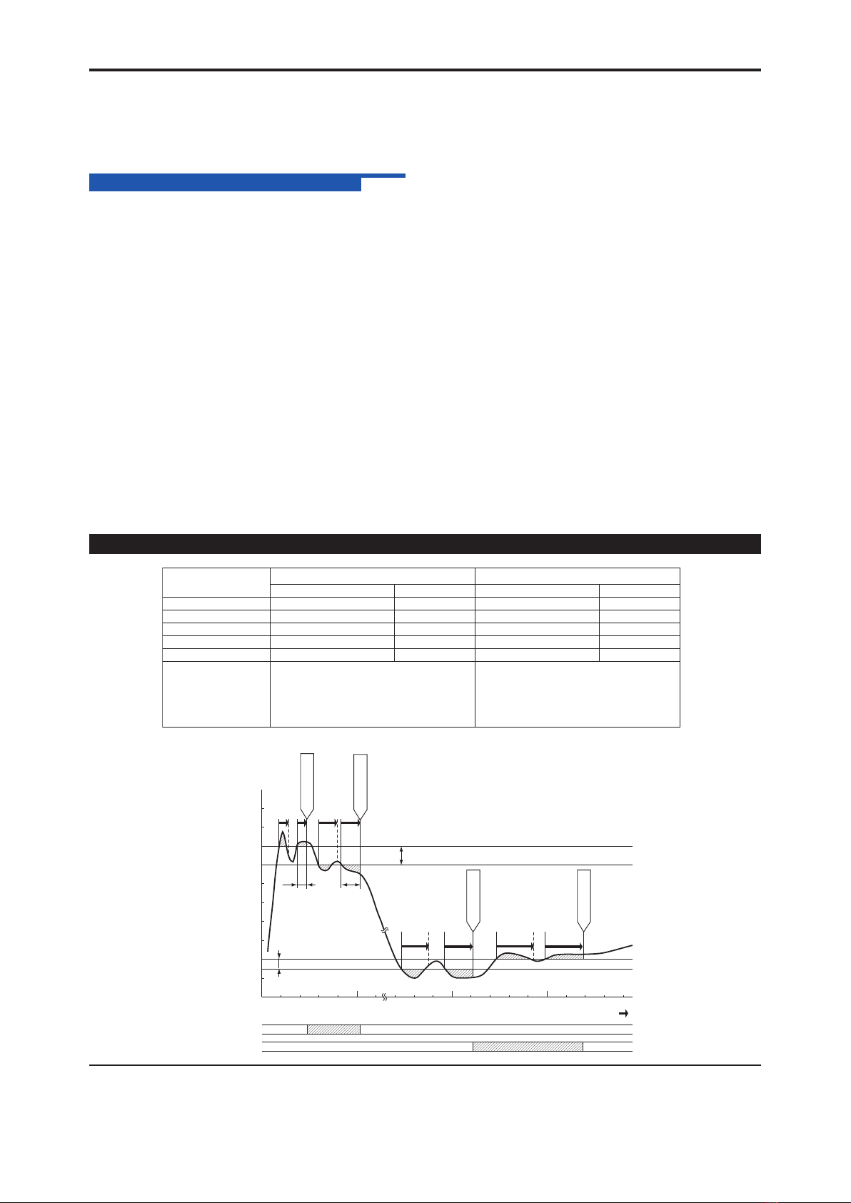
5.1.6 Pulse Width Type
Select and set “50%” (duty 50%), “ON PULSE” (ON-state
pulsewidthxed),or“OFFPULSE”(OF-statepulsewidth
xed)inD46:PULSETYPE.
5.1.7 Pulse Width Time
The pulse width time is set when the pulse width type is
set to “ON PULSE.”
SelectandsetthenumericalvalueinD47:PULSEWIDTH.
Pulsewidthsettingrange:0.1to500ms,by0.1ms
The output frequency when ON-state pulse width or OFF-
statepulsewidthisxedisasfollows.Thefrequency
over the following frequency is limited.
1
Pulse width set value(ms) x 2
x 1000[Hz]
5.2 Settings Related to Communication
Function
Setthefollowingparameterswhenoutput-2isspecied
for communication function. For more information on the
communication function, see the Instruction Manual for VJ
SeriesCommunicationFunction(IM77J1J11-01E).
5.2.1 Communication Protocol
Set the communication protocol by selecting from
amongPC-LINK,PC-LINKWITHSUM,MODBUSASCII,
MODBUSRTU,andLADDERinF01:PROTOCOL.
5.2.2 Communication Address
Set the address number of the isolator numerically in a
rangeof1to99inF02:ADDRESS.
5.2.3 Baud Rate
Set the baud rate by selecting from among 1200, 2400,
4800,and9600bpsinF03:BAUDRATE.
5.2.4 Parity
SelectandsetNONE,EVEN,orODDinF04:PARITY.
5.2.5 Data Length
Selectandset7bitsor8bitsinF05:DATALEN.

4
IM 77J01Q17-01E 4th Edition Mar.14,2016-00
5.2.6 Stop Bit
Selectandset1bitor2bitsinF06:STOPBIT.
5.2.7 Input Decimal Point Position
Namber of digits of decimal places (setting of D register
[D0003]) can be set.
Selectandsetamong0to5digitsinF07:INPUTDECPT.
5.3 Settings Related to Alarm Output
Setthefollowingparameterswhenoutput-2isspeciedforalarmoutput.
5.3.1 Alarm Setpoints
Setthealarmsetpointsofalarm-1andalarm-2inE03:
SETPOINT1andE04:SETPOINT2numerically.
• Settingrange:Arangeof0to100%ofinputrange
• Settingresolution:0.1%
5.3.2 Direction of Alarm Action
Select the direction of alarm-1 action and that of alarm-2
actionfromamongHIGHALM(high-limitalarm)and
LOWALM(low-limitalarm)andseteachinE05:ALM1
ACTION(directionofalarm-1action)orE06:ALM2
ACTION(directionofalarm-2action).
• Toactivatealarmstatuswheninputsignal≥alarm
setpoint,selectHIGHALM.
• Toactivatealarmstatuswheninputsignal≤alarm
setpoint,selectLOWALM.
5.3.3 Hysteresis
Setalarm-1andalarm-2hysteresis,inE09:
HYSTERESIS1andE10:HYSTERESIS2.Hysteresisis
a value added to the alarm setpoint in order for an alarm
status to be released (to normal) after the alarm status
has been activated. The alarm status will be released in
the following conditions, depending on the direction of
alarm action.
* WhenHIGHALM(high-limitalarm)isset:Alarmis
released when input signal < (alarm setpoint - hysteresis).
* WhenLOWALM(low-limitalarm)isset:Alarmisreleased
when input signal > (alarm setpoint + hysteresis).
• Settingrange:Arangeof0to100%ofinputrange
• Settingresolution:0.1%
5.3.4 Alarm ON Delay and Alarm OFF Delay
Setalarm-1andalarm-2ONdelaysinE11:ONDELAY1
andE12:ONDELAY2andthenalarm-1andalarm-2OFF
delaysinE13:OFFDELAY1andE14:OFFDELAY2.
An alarm ON delay is a delay time from the establishment
of alarm condition to alarm output; an alarm OFF delay is
a delay time from the establishment of return-to-normal
condition to output.
• Settingrange:0to999seconds
• Settingresolution:1second(Notethatabout0.2
second will be added to set time to prevent erroneous
operation.)
Forexample,whenanalarmONdelayissetto1second,
alarm output is generated if alarm status continues for
morethan1secondaftertheinputvalueexceedsthe
alarm setpoint. Further, when an alarm OFF delay is set
to 2 seconds, alarm output is released if normal condition
continues for more than 2 seconds after the input value
has returned to normal from the alarm status.
5.3.5 Direction of Relay Action
Setthedirectionofrelayenergizinginalarm-1normal
condition and alarm-2 normal condition by selecting
fromamongNRMDE-ENERGIZED(de-energizedunder
normalcondition)andNRMENERGIZED(energized
undernormalcondition)inE15:RL1ACTIONandE16:
RL2ACTIONandsetthem.
6. DESCRIPTION OF ALARM ACTIONS
Thischapterdescribesexamplesofalarmactionsunderthefollowingconditions.
metI 1-mral
A2
-mralA
retemaraPtniopte
Sr
etemara
Pt
niopteS
noitcamralafonoitceriDNOITCA1MLA:50Emralatimil-hgi
HN
OITCA2MLA:60
Em
ralatimil-woL
gnittesmralA1TNIOPTES:30E%082TNIOPTES:40
E%
51
siseretsyH1SISERETSYH:90E%012SISERETSYH:01
E%
5
yaledNOmralA1YALEDNO:11E.ces12YALEDFFO:21
E.
ces3
yaledFFOmralA1YALEDFFO:31E.ces22YALEDFFO:41
E.
ces4
mralafonoitpircseD
snoitca
tupniehterehwnoitidnocehtfisdnuosmralaehT
seunitnocmralatimil-hgihfoeromro%08sieulav
,sdnuosmralaehtretfA.dnoces1nahteromrof
nahtssel moresieulavtupnierehwnoitidnocehtnehw
nahteromrofseunitnocmralatimil-hgihehtfo%07
.lamronotsnrutersutatseht,sdnoces2
tupniehterehwnoitidnocehtfisdnuosmralaehT
seunitnocmralatimil-wolforo%51sieulav
,sdnuosmralaehtretfA.sdnoces3nahteromrof
nahtsieulavtupnierehwnoitidnocehtnehw
nahteromrofseunitnocmralatimil-wolehtfo%02
.lamronotsnrutersutatseht,sdnoces4
less
[%]
0
20
15
40
60
80
100 [1] [2]
[3] [4]
1 sec. 2 sec.
3 sec. 4 sec.
Alarm-2 hysteresis (5%)
Alarm-1 hysteresis (10%)
Alarm-1 setpoint (80%)
Alarm-2 setpoint (15%)
Elapsed time 1 sec.
Alarm-1 ON delay
Alarm-1 OFF delay
Alarm conditions
established
Alarm conditions
established
Normal conditions
established
Normal conditions
established
Low-limit alarm ON
Low-limit alarm OFF
Alarm-2 ON delay
Alarm-2 OFF delay
[1]: Alarm status does not continue for more than 1 second after the
alarm conditions are established at alarm-1.
[2]: Normal status does not continue for more than 2 seconds after the
normal conditions are established at alarm-1.
[3]: Alarm status does not continue for more than 3 seconds after the
alarm conditions are established at alarm-2.
[4]: Normal status does not continue for more than 4 seconds after the
normal conditions are established at alarm-2.
Alarm conditions established
High-limit alarm ON
High-limit alarm OFF
Normal conditions established
Alarm-1 action
Alarm-2 action
Alarm
Normal Normal
Normal Alarm Normal

5
IM 77J01Q17-01E 4th Edition Mar.14,2016-00
7. LIST OF PARAMETERS
Parameter Display Item
MODEL Model
TAGNO Tag no.
SELFCHK Self-check result
A DISPLAY1 Display1
A01 INPUT1 Input value
A05 OUTPUT Output value
A07 ALM1 STATUS Alarm-1 status
A08 ALM2 STATUS Alarm-2 status
A54 STATUS Status *1
A56 REV NO Rev. no.
A58 MENU REV MENU REV
A60 SELFCHK Self-check result
B DISPLAY2 Display2
B01 INPUT1 Input value
B05 OUTPUT Output value
B07 ALM1 STATUS Alarm-1 status
B08 ALM2 STATUS Alarm-2 status
B60 SELFCHK Self-check result
D SET (I/O) Setting (I/O) *2
D01 TAGNO.1 Tag no. 1
D02 TAGNO.2 Tag no. 2
D03 COMMENT1 Comment1
D04 COMMENT2 Comment2
D10 UNIT Output range unit
D14 LOWCUT Low output cut point
D16 INPTYPE Input type
D17 SELECTRANGE Selection of input hard range
D18 INP RESIST Input resistance
D22 INPUT1L_RANGE Input low range
D23 INPUT1H_RANGE Input high range
D24 OUTL_RANGE Output low range
D25 OUTH_RANGE Output high range
D46 PULSETYPE Pulse width type
D47 PULSEWIDTH Pulse width time
D60 SELFCHK Self-check result
E SET(ALM) Setting (alarm output) *2
E03 SET POINT1 Alarm-1 setting
E04 SET POINT2 Alarm-2 setting
E05 ALM1ACTION Direction of alarm-1 action
E06 ALM2ACTION Direction of alarm-2 action
E09 HYSTERESIS1 Alarm-1 hysteresis
E10 HYSTERESIS2 Alarm-2 hysteresis
E11 ONDELAY1 Alarm-1 ON delay setting
E12 ONDELAY2 Alarm-2 ON delay setting
E13 OFFDELAY1 Alarm-1 OFF delay setting
E14 OFFDELAY2 Alarm-2 OFF delay setting
E15 RL1ACTION Direction of alarm-1 relay action
E16 RL2ACTION Direction of alarm-1 relay action
E60 SELFCHK Self-check result
F SET(COM) Setting (communication) *2
F01 PROTOCOL Communicationprotocol
F02 ADDRESS Address
F03 BAUD RATE Baud rate
F04 PARITY Parity
F05 DATA LEN Data Length
F06 STOP BIT Stop bit
F07 INPUTDECPT Decimal point position of input
F60 SELFCHK Self-check result
P ADJUST Adjustment
P02 ZEROADJ1 Zeroadjustmentofinput
P03 SPAN ADJ1 Span adjustment of input
P17 RESISTOR ADJ Adjustmentofexternalinput
resistance
P60 SELFCHK Self-check result
Q TEST Test *2
Q04 ALM1 TEST Forced output (alarm 1)
Q05 ALM2 TEST Forced output (alarm 2)
Q08 OUT TEST Forced output
Q60 SELFCHK Self-check result
*1 The Status is displayed for service personnel to see
history records.
*2 There are items not displayed depending on what
output-2isspecied.
8. MAINTENANCE
The product starts running immediately when the power is
turned on; however, it needs 10 to 15 minutes of warm-up
beforeitmeetsthespeciedperformance.
For cleaning the instrument, use a soft and dry cloth.
8.1 Calibration Apparatus
• Acalibrator(YOKOGAWACA150orequivalent)
• Aprecisionresistorof250Ω±0.01%,1W(forcurrent
output)
• Settingtoolforadjustment(Referto“4.2Connectingthe
Setting Tools” in this manual.)
8.2 Calibration Procedure
1. Connecttheinstrumentsasshowningurebelow.First
adjust the output-1 signal and then the output-2 signal.
Input
R: Externally connected
for current input
R: 250 Ωprecision resistor
for current input
Shunt resistor
(Externally connected
for current input)
Voltage and
current
Generator
Voltage and
current
Generator
Voltage and
current
Generator
Voltage and
current
Generator
Voltage and
current
Generator
Output-1
Alarm-1
Alarm-2
Output-2
1011
3 2 1
4
56
789
Power supply
1110 8
L+N–GND
1
3
+
–
2
5
R
+
–
2
5
ALM1
(N.O.)
COM
+
–
6
5
ALM2
(N.O.)
COM
+
–
7
9
R
+
–
2. Produce input signals equivalent to 0, 25, 50, 75 and
100% of the input span to the converter from the voltage
and current generator.
3. Then, check that the converter’s output signal shows
voltages corresponding to 0, 25, 50, 75, and 100% of the
input span within the rated accuracy range.
Take the same calibration procedure for the output-2, and
conrmthatthefrequencyoftheoutput2isthesameas
that of the output 1.
• If the output signal is out of the rated accuracy range,
adjusttheoutputsignallevelusingtheHandyTerminal
(JHT200).
For adjustment using a setting tool, refer to the User’s
Manual for each setting tool and “7. List of Parameters” in
this manual.
User’sManualforVJ77[DocumentNo.:IM77J01J77-01E]
User’sManualforJHT200[DocumentNo.:IM77J50H01-
01EN]
Note
When power of VJQ7 is turned on/off, one pulse
may be counted by the pulse input device which
connects to the VJQ7.

Blank Page
Table of contents
Popular Media Converter manuals by other brands

Veris Industries
Veris Industries GWNP Series installation guide

Blankom
Blankom HDM-8512C Data Sheet and Instruction Manual

Kaiser Baas
Kaiser Baas KBA03026 troubleshooting guide

Anttron
Anttron TM170HD user manual

Danfoss
Danfoss VLT Micro Drive FC 51 Series operating instructions

ADF Web
ADF Web HD67412 user manual