JVA ZLM4 User manual

© JVA Technologies Pty Ltd Page 1 of 32 Issue:3/03/2021 9:39:00 AM
OEM technical manual.docx
ZLM4 OEM Technical Manual
Version 5, March 2021

© JVA Technologies Pty Ltd Page 2 of 32 Issue:3/03/2021 9:39:00 AM
OEM technical manual.docx
Contents
INTRODUCTION ..........................................................................................................................................................4
Scope and Purpose...................................................................................................................................................4
Latest Version ...........................................................................................................................................................4
Features.................................................................................................................................................................5
Limitations..............................................................................................................................................................5
Equipment Requirements and Options.........................................................................................................................6
Requirements............................................................................................................................................................6
Options......................................................................................................................................................................6
OPERATION.................................................................................................................................................................7
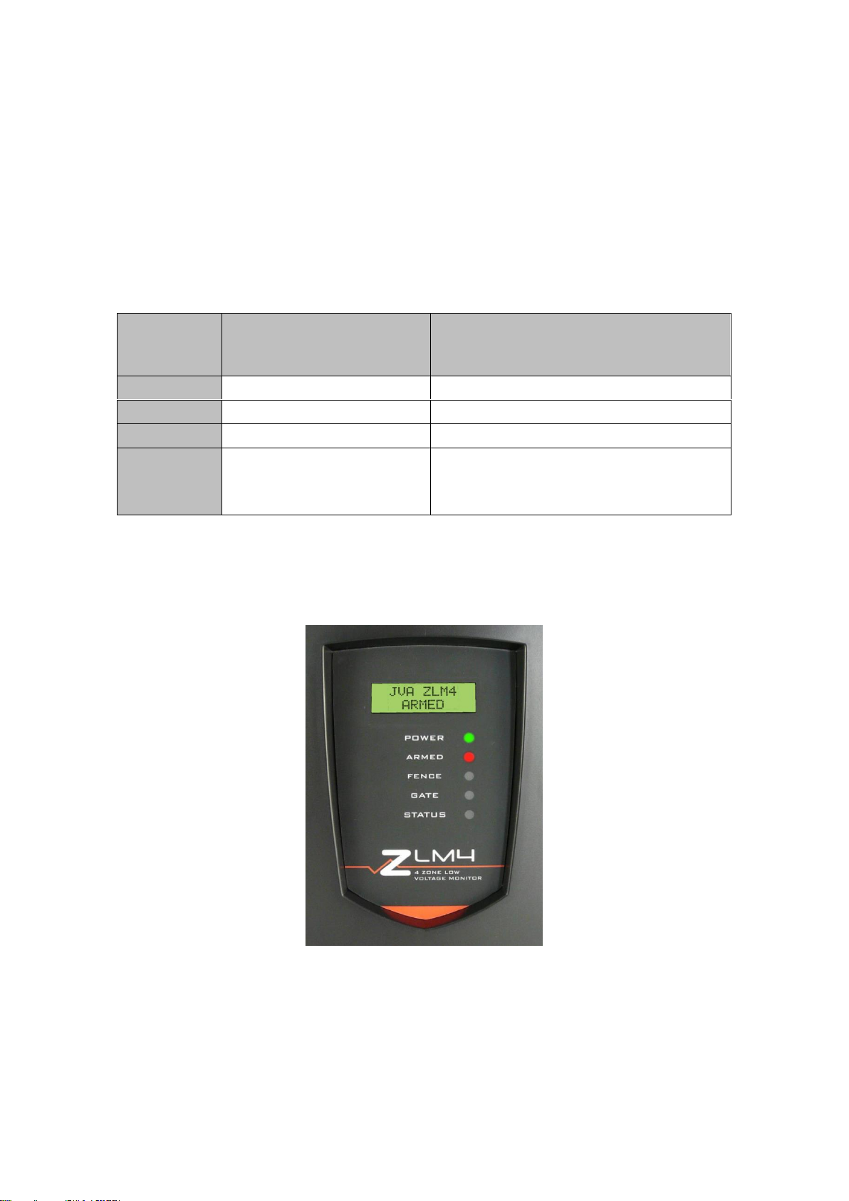
Status LED Lights .....................................................................................................................................................7
LCD display...............................................................................................................................................................7
ZLM4 LCD Screen ....................................................................................................................................................8
Control Options .........................................................................................................................................................9
Control Arbitration .....................................................................................................................................................9
Control inputs............................................................................................................................................................9
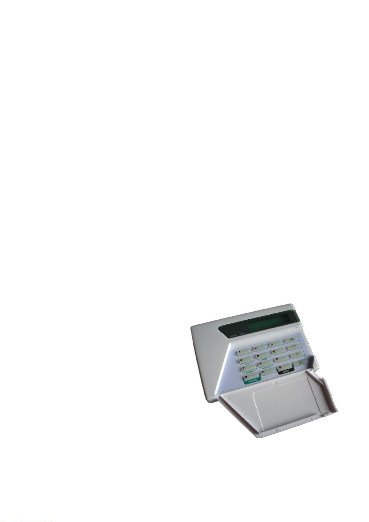
Keypad Control..........................................................................................................................................................9
Keypad Versions.....................................................................................................................................................10
Arming/Disarming the Fence Using the Keypad.....................................................................................................10
Keypad Status Display............................................................................................................................................10
When an Alarm Occurs...........................................................................................................................................10
To Silence the Alarm...............................................................................................................................................11
To Disarm................................................................................................................................................................11
To Clear Alarm Memory..........................................................................................................................................11
Changing your User PIN .........................................................................................................................................11
Standby Battery.......................................................................................................................................................11
Internal Beeper/Keypad Beeper..............................................................................................................................11
ZLM4 Relevant Keypad Codes...............................................................................................................................12
SPECIFICATIONS......................................................................................................................................................13
INSTALLATION ..........................................................................................................................................................14
Installation Steps.....................................................................................................................................................14
Jumper Configuration..............................................................................................................................................15
Fence Terminals .....................................................................................................................................................15
Control, Power and IO Terminals............................................................................................................................16
Fence Wiring Diagrams...........................................................................................................................................17
Standalone fence continuity monitor ...................................................................................................................17
Low Voltage Zoning System................................................................................................................................18
Wiring Diagrams......................................................................................................................................................19
Combining the ZLM4 with a Z Series energiser......................................................................................................19
Fence Wiring .......................................................................................................................................................19
Keypad Bus Wiring..............................................................................................................................................20
Example group wiring diagrams..........................................................................................................................21
Z28 and two ZLM4 connected to Perimeter Patrol through a PAE223 (USB Interface).....................................21
TECHNICAL INFORMATION.....................................................................................................................................22
LCD Error messages...............................................................................................................................................22
PROGRAMMING OPTIONS.......................................................................................................................................22
Enter Programming mode.......................................................................................................................................22
To exit programming mode .....................................................................................................................................23
Changing the installer PIN ......................................................................................................................................23
Changing an Option ................................................................................................................................................23
Programmable Options Table.................................................................................................................................24
Programming Options in Detail...............................................................................................................................25
Zone 1 Fence Voltage Alarm Level (01xx#)........................................................................................................25
Zone 2 Fence Voltage Alarm Level (02xx#)........................................................................................................25
Zone 3 Fence Voltage Alarm Level (03xx#)........................................................................................................25
Zone 4 Fence Voltage Alarm Level (04xx#)........................................................................................................25
Missed Pulse Count (06xx#)................................................................................................................................25
Battery Alarm Voltage (07x#) ..............................................................................................................................25
Siren on Time (08x#)...........................................................................................................................................26
Siren Off Time (09x#) ..........................................................................................................................................26
Siren Cycles (10x#) .............................................................................................................................................26
Input Type (11x#) ................................................................................................................................................26

© JVA Technologies Pty Ltd Page 3 of 32 Issue:3/03/2021 9:39:00 AM
OEM technical manual.docx
Input 2 Function (12x#)........................................................................................................................................26
Gate Delay (13x#) ...............................................................................................................................................27
Chime mode (14x#).............................................................................................................................................27
Fence Mode (15x#) .............................................................................................................................................27
Binary Options (16x#)..........................................................................................................................................27
Zones (not yet implemented)........................................................................................................................27
Auto Re-Arm time (20x#).....................................................................................................................................28
Relay Functions...................................................................................................................................................29
Group Mode (26x#) .............................................................................................................................................30
Keypad programming .................................................................................................................................................31
Changing the Keypad Messages and Address.......................................................................................................31
Keys used for changing messages: ....................................................................................................................31
To Exit Keypad Programming.................................................................................................................................31
Connecting Multiple Keypads to a system..............................................................................................................31
Notes Regarding Keypad Configuration .................................................................................................................32

© JVA Technologies Pty Ltd Page 4 of 32 Issue:3/03/2021 9:39:00 AM
OEM technical manual.docx
INTRODUCTION
The ZLM4 is a 4 zone low voltage electric fence monitor. The ZLM4 may be used by itself or in conjunction with a
number of high voltage security electric fence energisers. The ZLM4 monitors up to 4 loops of fence wire, each up
to several hundred meters long, to detect someone tampering with the fence by cutting or shorting the wires.
When used in conjunction with a high voltage electric fence energiser the ZLM4 is wired to the non energised earth
wires on the fence. In this way the ZML4 can be used to split one high voltage zone into up to 4 low voltage
monitored zones for improved targeting of the response to potential security breaches.
The ZLM4 is compatible with the JVA Z series energisers. It may be connected via a Keypad bus network with
other Z series devices to enable the whole group to be controlled via one keypad, or linked to a PC running
Perimeter Patrol.
The ZLM4 monitors a low voltage loop using intrinsically safe, isolated ELV DC. It employs a continuity check for
detecting open circuits, DC voltage level sensing to detect a short to ground and pulse voltage sensing to detect a
short to a line powered by a high voltage fence energiser.
The advanced features of this device allow the performance to be tuned to the fence and to the particular
requirements of the site. This is done by adjusting the devices programmable options.
The ZLM4 will report an alarm on seeing a low voltage loop cut (open circuit), shorted to ground (short), when high
voltage from an electric fence energiser wire is shorted to the monitored low voltage loop or when two low voltage
loops short to one another (cross couple).
Scope and Purpose
•This document is intended for the training of engineering and technical personnel both internally at Pakton
and for our OEM customers.
•As a reference for the features and specifications per version, as such it will be kept up to date and re-
issued with each revision of the PCB or firmware. Please ask Pakton for the latest version.
•The users / installation manual will be drawn directly from this material (reformatted). Information NOT
meant to be included to end users should be identified by an “OEM only” comment.
This manual relates to:
PCB versions: 1.00 or higher
Firmware version: 1.00 or higher (the firmware version is shown on the LCD after reset)
Current Firmware: 1.33
Latest Version
The latest version of this OEM manual should be available from here.
The latest version of the Users manual should be available from here.

© JVA Technologies Pty Ltd Page 5 of 32 Issue:3/03/2021 9:39:00 AM
OEM technical manual.docx
Features
•Monitors for continuity using safe 50V DC pulses.
•Can be used to split a single security electric fence zone into up-to 4 low voltage zones
•Can detect a short to ground, high voltage short, open circuit (fence cut) and cross couple
•LCD display, displays which zone is in alarm and other information
•Controlled and Programmed via a JVA keypad with similar codes to the JVA Z series
Compatible with all JVA Z series network adaptors including :
oUSB
oAble to be monitored via PC (using Perimeter Patrol software version 5.3 or above)
oRS485
oTCP/IP
oSMS Gateway
oNimbus Gateways and Cloud Router
•Able to be integrated into third party access control and security information management systems at a
variety of levels
•Enables the construction of systems from economical Key switch operation to complex PC controlled
applications
•Built into the wall mountable Z series energiser enclosure
•Runs from 16Vac or 12V DC external source
•In built battery charger and for optional 7aH back up battery
•Siren and Strobe switched 12V DC outputs for standalone operation
•2 control inputs and 4 form C relays with many programmable functions for low level integration with other
systems
•Fence connections are fully isolated from power and IO
Limitations
•Any energiser used with the ZLM4 must comply with IEC60335.2.76 electrical safety standard
•Energisers with a negative voltage pulse may not be suitable
•The energiser output pulse energy must not exceed 18 Joules
•The maximum series resistance of the fence wire loop which can be accurately monitored is 5000 Ohms
•* Not all versions of the PAE212, PAE224 or PAE218 GSM module recognise the ZLM4. For compatibility
please check with your distributor or JVA
•The JVA LCD keypad (PTE0210) requires version 2.12 or later firmware to operate with a ZLM4, the
keypad firmware can be viewed by at power up or by pressing *9# on the keypad.
•Perimeter Patrol version 5.2.2 or later is required to operate with a ZLM4

© JVA Technologies Pty Ltd Page 6 of 32 Issue:3/03/2021 9:39:00 AM
OEM technical manual.docx
Equipment Requirements and Options
Requirements
•12V rechargeable backup battery or external 12V source
•16Vac or 24Vdc power adaptor if using internal rechargeable battery
Options
•12V Siren and strobe light
•LCD Keypad (PTE0210). Note 1,2
•Windows PC
oWindows XP or later
oPAE223 or PAE100 serial adaptor AND USB to serial adaptor
oor PAE212 TCP/IP adaptor
oPakton Perimeter Patrol PC application
•Cellular, Wi-Fi or LAN Gateway and a Cloud Router account.
Notes
1. While the Keypad is not essential for normal operation, it is required to adjust the programmable options.
2. Up to 3 Keypads may be connected in parallel on a ZLM4, each Keypad must have a unique ID setting.
3. The ZLM4 contains patent pending technology, contact JVA for more information.
For more information please see www.jva-fence.com.au

© JVA Technologies Pty Ltd Page 7 of 32 Issue:3/03/2021 9:39:00 AM
OEM technical manual.docx
OPERATION
Status LED Lights
The status LED’s on the front of the ZLM4 allow the user to quickly ascertain the current status of the unit and if
any action needs to be taken. Below is a brief description of each LED (top to bottom) and the information it
conveys.
Power
-
On (Green) whenever the unit has power.
Armed
-
On (Red) when the unit is armed, flashes if any zone is bypassed
Fence
-
On (Red) when there is a fence alarm (any zone), flashes if any zone has a low voltage
Gate
-
On (Red) when there is a gate alarm, flashes if the gate is open
Status
-
Flashes (Red) an error code for service errors. The LCD may also show an error message.
Status LED
Number of
Flashes
Interpretation
Corrective \Action
1
Not used
2
16Vac Mains fail
Restore mains power
3
Low battery, bad battery
Charge or replace battery
4
PCB service fault
Return to repair/service centre
Note: A Z slave will show this error if
disconnected from the Master
LCD display
The Optional LCD display shows the status of the ZLM4 at all times.

© JVA Technologies Pty Ltd Page 8 of 32 Issue:3/03/2021 9:39:00 AM
OEM technical manual.docx
ZLM4 LCD Screen
The ZLM4 will show the status on the optional LCD display.
When disarmed
While armed, the LCD display cycles the following information.
Pressing # on the keypad will freeze the current information displayed on the LCD screen for approximately 10
pulses. Pressing the # key again will cycle the display to the next information screen.
When an alarm occurs the screen will detail the type of alarm and the sector if applicable.
Various “troubles” are also displayed, such as AC fail or low battery.
When the ZLM4 is disarmed, all current alarms are shown.
The display also shows the programmable options and values when in programming mode.
1:Alarm V1
Value: 20
Alarm:Zone1
Gnd Short
JVA ZLM4
Disarmed
Battery
11.5V
AC Fail
ALARM
Energiser Fail
ALARM
Gate
Alarm:Zone3
HV Short
Alarm:Zone2
Fence Cut
Alarm:Zone1
Gnd Short
Battery 14.5V
AC On
ZLM4 Armed
All clear
1:35V 2:37V
2:40V 4:35V
JVA ZLM4
Disarmed

© JVA Technologies Pty Ltd Page 9 of 32 Issue:3/03/2021 9:39:00 AM
OEM technical manual.docx
Control Options
The ZLM4 may be armed and disarmed (controlled) using a:
•Key switch or remote switch connected to the control input (IN1)
•Remote control radio receiver connected to IN1
•Z Series Keypad
•Smart phone linked to a Cloud Router account
•Windows PC running JVA Perimeter Patrol
•Low level interface (wired to control inputs and relay outputs) from a third part security alarm panel or
Physical Security Information System (PSIM)
Note: More than 1 method may be used in the one installation.
Control Arbitration
If an installation contains two ways to control the ZLM4, then the most recent control signal will determine the
Armed/Disarmed state. For example if the ZLM4 is armed via the keypad and then disarmed at the control input
(IN1) it will disarm.
The higher level control methods such as the PC control software may override the Control input and Keypads
methods, depending on the options used. If you need to make sure that fence is disarmed (for maintenance) then
using the Key switch or keypad alone may not guarantee that the fence will remain disarmed.
Control inputs
The ZLM4 may have a single Key switch mounted on the right hand side of the cabinet which may be used to arm
and disarm the security electric fence to which it is connected. This switch is useful for the simplest
implementations where no keypad or PC control program is used. It may be disabled by the installer, by removing
the lead from socket J2.
When switched on via the Key switch (or a switch connected to IN1) the ZLM4 will power up the energiser it is
coupled to and begin monitoring the fence.
The screen will change to display the Armed status and any faults or alarms. If there is a fence fault the ZLM4 will
go into alarm, the internal beeper will sound (if it has not been inhibited) and any siren and strobe connected to the
ZLM4 will be turned on.
The zone in which the fault has occurred will be displayed.
Switching the Key switch off will disarm the ZLM4, though it will continue to display the last alarm and zone.
Keypad Control
The ZLM4 uses the same keypad as the Z series
energisers and is controlled using similar keypad codes.
The PTE0210 keypad (Version 2.00 and higher) will
display the Fence voltages plus the zone if in fence
alarm.
Alarms and troubles will also be displayed.
The Keypad has two LED lights
Power
On with Mains power, Off with Main
fail, flashes on low battery
Armed
On when the energiser is armed,
flashes when in low power mode
All other indication is given via messages on the keypad
LCD screen.
If the Keypad shows “Alarm” or “Trouble” pressing [#]
will reveal more information about the problem.
NOTE: There is no panic function currently implemented.

© JVA Technologies Pty Ltd Page 10 of 32 Issue:3/03/2021 9:39:00 AM
OEM technical manual.docx
Keypad Versions
The current version keypad is a PTE0210 with code version 2.00. Older versions have limitations.
The keypad version can be seen by pressing *9#.
PTE0200 Shows “ALPHA KEYPAD Revision 7.0”
•Cannot show Zone (fence) voltages
•Shows only Zone alarms 1-8
•Does not show Gate alarms
PTE0210 Shows “PTE0210” and the code version.
•Can show fence voltages
•Will respond to *68# to analyse the “group”.
•Version 1.21 and below
oOlder version, can be upgraded to V2.00 firmware.
oCannot detect or operate with the ZLM4.
•Version 2.20 and higher
oZLM4 is supported, zones are displayed.
PTE0230 Android based touch screen keypad
•Provides the most advanced monitoring and control of all Z range devices
•All functions are available
•Refer to the inbuilt help, the rest of this chapter refers to the simpler LCD keypads above.
Arming/Disarming the Fence Using the Keypad
Enter your User PIN (Personal Identification Number: four digits long) and push the # key. Make sure the red ARM
light comes on and the keypad beeps twice to confirm that the system is armed.
The fence will power up and if all is well (no faults) the system will be ready to deter and detect.
To disarm the system, enter your User PIN and press #.
Note: If there is an alarm sounding you will need to enter your PIN twice, once to silence the alarm and once more
to disarm.
See also the section on programming Keypads.
Keypad Status Display
In normal operation the keypad shows a continuous summary of the system status. For example if the system is
disarmed the keypad will display “Ready to Arm”.
If the system is armed then the keypad will display the voltages for each zone in the system.
Since there can be many things to display the keypad automatically “scrolls” through all relevant detail. Each
screen is show for about 2 seconds. If you wish to hold the display at a particular point simple press the [#] key.
The auto scrolling will stop for about 20 seconds.
Pressing the [#] key again will advance the display one step.
If a new trouble (AC fail, low battery etc) or alarm occurs, the keypad screen will jump to the relevant zone, the
keypad will beep (unless toggled off) and auto scrolling will cease for about 3 minutes.
When an Alarm Occurs
An Alarm will occur if there is a fault on the fence caused by a short or an open circuit (cut), while the system is
armed. The siren will sound and the strobe will light. The internal beeper and the Keypad may also sound,
depending on how your system is configured.
There are 3 ways the ZLM4 can detect a fence fault:
1) A low voltage circuit is cut (open circuit)
2) A low voltage circuit is shorted to ground (LV short)
3) A high voltage wire shorts to a low voltage wire (HV Short)
Note: If the ZLM4 is monitoring a fence that has a disarmed energiser on it, a ground alarm will occur when one of
the HV wires touches a LV wire. This is because the ZLM4s pulse will ground through the energisers transformer.
Whilst the ZLM4 is correct in stating that there is a ground short, please be aware of this when diagnosing fence
faults.
The siren and keypad beeper will sound and any relays assigned to this fence alarm will turn on.

© JVA Technologies Pty Ltd Page 11 of 32 Issue:3/03/2021 9:39:00 AM
OEM technical manual.docx
An alarm will also sound if Control Input 2 is assigned to the “gate” function and the gate input is opened for longer
than the Gate delay time.
After the siren has cycled on and off according to the times and numbers set in options, the siren will stop
sounding. The on and off timing can be set in the programmable options. The Strobe will remain on. After a further
delay (Auto Rearm Time) the siren will again respond to the next alarm condition with a new set of on / off cycles.
If the alarm condition is removed, the siren will stop after the end of the current “on” time (Siren On Time).
If the siren is silenced (by entering PIN#) then the siren will enter the next “off” cycle (Siren Off Time). If the alarm
condition is still present (voltage is low) the siren will sound again after the preset “off” time. If the alarm condition is
not present the Energiser is instantly rearmed, irrespective of the auto-rearm setting.
To Silence the Alarm
If there is no Keypad attached simply disarm the ZLM4 using the Key switch or magnetic fob.
Using a Keypad, enter your User PIN and press #. This will silence the alarm but not disarm the system; the armed
light will still be on. The system will be ready for the next alarm.
Note: This silence function will not operate if the ZLM4 is part of a Z series “group”.
The last alarmed Zone will still be displayed on the front panel LCD and the Keypad.
The siren and strobe are ready to respond again if triggered.
To Disarm
If there is no Keypad attached simply disarm the ZLM4 using the Key switch or magnetic fob.
Using a Keypad, disarm the system by entering your User PIN and press #.
The Fence or Gate light on the ZLM4 will remain on to show the Alarm memory. This can be cleared by entering
the Clear Alarm memory command *1#. The Alarm memory will also be cleared when the ZLM4 next Arms.
To Clear Alarm Memory
After an alarm occurs, pressing *1#, will clear the alarm memory. If the problem still exists the unit will alarm again.
Changing your User PIN
Enter the current 4 digit PIN and press *0#. This enters User Programming mode.
Enter your new PIN (must be 4 digits) and then #.
Press *# to exit User Programming mode.
Make sure your new PIN works by using it to arm the energiser.
The default User PIN is 1234.
For example, the following Keypad sequence will change the User PIN to 8015 from the default PIN:
1 2 3 4 * 0 # 8 0 1 5 # * #
Standby Battery
Should there be a loss of mains power, the Power light on the keypad will go off. The status LED on the ZLM4 front
panel will flash twice and the Keypad will show Trouble –AC Fail.
If the loss of power is prolonged, the battery may become discharged and become ineffective. The Power light on
the keypad will start to flash indicating that the battery charge is low. The status LED on the ZLM4 front panel will
flash three times and the Keypad will show TROUBLE: LOW BAT
If the standby battery requires replacement, the Status LED on the Energiser will flash 3 times even after the mains
power has been restored.
Internal Beeper/Keypad Beeper
Depending on the Chime Mode setting, the internal beeper and keypad beeper will sound when there is a fence
alarm, a gate alarm, a general alarm or a door chime. On flat battery the keypad will always beep 4 times before
the energiser automatically enters low power mode to preserve the battery. On AC Fail it will not beep.
Note: The Internal beeper also beeps at Power up.

© JVA Technologies Pty Ltd Page 12 of 32 Issue:3/03/2021 9:39:00 AM
OEM technical manual.docx
ZLM4 Relevant Keypad Codes
Function
Key Sequence
Arm/Disarm
[User PIN][#]
Silence an alarm (Single zone system only)
[User PIN][#]
Start Programming the Z series energiser
[Installer PIN][*] [0] [#]
Start Programming the Keypad
[Installer PIN][*] [0] [1] [#]
Exit Programming (any mode)
[*] [#]
Change a User PIN
[User PIN][*][0][#][New PIN]#
Change the Installer PIN
[0] [0] [New Installer PIN][#]
Arm All Zones (Multi-zone groups)
[User PIN][*][1][0][#]
Arm Zone 1 (Master)
[User PIN][*][1][1][#]
Arm HV Zone x, where x is any zone number up to 15
[User PIN][*][1][x][#]
Disarm All Zones
[User PIN][*][2][0][#]
Disarm HV Zone 1 or Master
[User PIN][*][2][1][#]
Disarm HV Zone x, where x is any zone number up to
15 (Note 1)
[User PIN][*][2][x][#]
Arm Gate circuits only
[User PIN][*][4][#]
To change the Keypad Messages to English
[*][3][1][#]
To change the Keypad Messages to Spanish
[*][3][2][#] (not well supported yet)
Keypad Audible Feedback Toggle
[*] [5] [1] [#]
Keypad Chimes Toggle On/Off
[*] [5] [3] [#]
Keypad Error Tones Toggle On/Off
[*] [5] [4] [#]
Keypad Alarm Tones Toggle On/Off
[*] [5] [5] [#]
Backlight Toggle On/Off
[*] [8] [#]
Display Keypad Model
[*] [9] [#]
Analyse Group
[*][6][8][#]
Reset and Display firmware version number
[User PIN][*][6][8][#]
Reset and return to factory defaults
[Installer PIN][*] [6] [8] [#]
Siren test
[*] [6] [3] [#]
Battery test
[*] [6] [4] [#]
Clear Alarm memory
[*] [1] [#]

© JVA Technologies Pty Ltd Page 13 of 32 Issue:3/03/2021 9:39:00 AM
OEM technical manual.docx
SPECIFICATIONS
The specifications table below outlines the power consumption of the ZLM4 and the acceptable voltage and current
ranges for different inputs and outputs.
Internal battery charger float voltage
14.2Vdc
Internal battery charger charging current
1200mA
Power consumption of ZLM4 (Note 1)
130mA at 12.5
Vdc
Maximum AC input voltage when internal battery charger is supplying 580mA
19Vac
Battery backup time (without keypad)
24 Hours
Maximum voltage on “In1”, “SW2”and “Gate”inputs (Note 2)
5Vdc
Maximum power provided to “Siren” and “Strobe” outputs (Note 3)
35Watts (2.5A at
13.5V)
Maximum Energiser Joules (Note 4)
18J
Maximum loop impedance
5000 Ohm
Maximum loop capacitance to ground
1.0uF
Minimum loop resistance to ground
1000 Ohm
Note 1: This is the power consumption when none of the powered outputs are active and the keypad is not
connected. The rated power consumption may be lower depending on relay configuration and alarm states.
Note 2: The control inputs as supplied with 5V from a “weak pull up” circuit so that they can be controlled using dry
contacts from a relay or switch. A device with “open collector” outputs may be used. They can also be driven from a
5V switched output, so long as the driving circuit actively pulls down to ground when off.
Note 3: This is the limit for the combination of the loads on both the “Siren” and “Strobe” outputs.
Note 4: This is the maximum rating of the energiser if the ZLM4 is used on the same fence as a high voltage
electric fence energiser. Beyond this rating the ZLM4 loop circuit protection MOV’s may fail if high voltage wires are
shorted to the ZLM4 loop wires.

© JVA Technologies Pty Ltd Page 14 of 32 Issue:3/03/2021 9:39:00 AM
OEM technical manual.docx
INSTALLATION
It is recommended that all installations are performed by qualified technicians.
Installation Steps
1. Read the entire ZLM4 and Energiser manuals first!
2. Design and build the fence. (Beyond the scope of this manual.) Ask your distributor for help if required.
3. Decide where the energiser, ZLM4 and Keypad are to be mounted. If on an external wall it should be
housed within a weatherproof equipment box, shaded from direct sun.
4. Remove the lid of the ZLM4 using a 5mm Hex key.
5. Remove the ZLM4 PCB chassis from the housing by removing the two screws at the top corners.
6. Mount the housing by using 4 screws through the rear of the box. The box must be mounted to a wall
in such a way that all of the 4 holes in the rear of the case are against the mounting surface.
7. Replace the PCB chassis.
8. If using a keypad, remove the rear housing of the keypad and fix it to the wall.
9. Wire the low voltage cables to the PCB terminals.
10. Wire the high voltage cable to the PCB terminals.
11. Set the Jumpers as required
12. Fit the battery leads to the battery. The Error LED should be blinking twice to show mains fail.
13. Replace the front cover (lid).
14. Turn AC power on.
15. Arm the ZLM4 and Switch on the Energiser if used. The LCD display will now show the zone voltages.
16. Find and remove any faults on the fence
17. Test that a short in any zone puts the ZLM4 into alarm and shows the correct Zone

© JVA Technologies Pty Ltd Page 15 of 32 Issue:3/03/2021 9:39:00 AM
OEM technical manual.docx
Jumper Configuration
The ZLM4 is equipped with three jumpers, two of which (J3 and J4) operate in an identical fashion to those on the
Z14. The third jumper, J8 will suppress the beeper on the ZLM4 when fitted.
These are located in the top left corner of the PCB.
Jumper
Function
Purpose
J3
Inhibit Mains fail error.
J3 is fitted to inhibit Mains fail errors if the
intention is to operate the energiser on DC
only (as in solar power systems).
J4
Factory default jumper
Off to return programmable options to
factory defaults on power up.
If the energiser needs to be defaulted to
factory settings, remove all power (AC and
battery) and remove the J4 jumper. Reapply
the mains and the battery power. Reapply the
J4 jumper and the Energiser will be reset to
default settings.
J8
Inhibit internal Beeper
Fitted to inhibit the internal beeper,
irrespective of any option setting.
Fence Terminals
Description of fence terminals (Left to Right)
Loop 1
Connect to zone 1 fence wires
Loop 2
Connect to zone 2 fence wires
Loop 3
Connect to zone 3 fence wires
Loop 4
Connect to zone 4 fence wires
Ground
Connect to main fence earth stakes.

© JVA Technologies Pty Ltd Page 16 of 32 Issue:3/03/2021 9:39:00 AM
OEM technical manual.docx
Control, Power and IO Terminals
Label
Type
Description
IN1
2 Way
Energiser control input (dry contact). Defaults to normally open.
Can be used for a remote switch or a radio receiver. The receiver may be powered
from the keypad +12V terminal.
Gate
2 Way
Energiser control input, defaults to normally open low power but may also be
assigned to gate input. When the unit is armed and the gate is opened, it will trigger
the gate alarm.
Keypad
3 Way
Supplies power and data line for an external keypad. The +12V source on these
terminals is protected with 1A self resetting fuse.
Siren
2 Way
Switched 12 volt output. Low side switched. 35W max (including strobe). A buffer
relay should be used when connecting these outputs to an alarm panel.
Strobe
2 Way
Switched 12 volt output. Low side switched. 35W max (including siren). A buffer
relay should be used when connecting these outputs to an alarm panel.
AC IN
3 Way
16Vac power input. Fused via F3 3A self resetting fuse. Note: 24Vdc may also be
used, in which case the polarity should be + to the left pin.
The Earth terminal (far right) may be required to be connected to mains earth in
some countries, consult your local wiring guidelines.
Relay 3
3 Way
May be set to any of 16 alarm conditions. Defaults to zone 1 alarm.
Relay 4
3 Way
May be set to any of 16 alarm conditions. Defaults to zone 2 alarm.
Relay 5
3 Way
May be set to any of 16 alarm conditions. Defaults to zone 3 alarm.
Relay 6
3 Way
May be set to any of 16 alarm conditions. Defaults to zone 4 alarm.
J5
Jumper
Short these two contacts to provide +12v power to the common contact of Relay 3.*
J6
Jumper
Short these two contacts to provide +12v power to the common contact of Relay 4.*
J7
Jumper
Short these two contacts to provide +12v power to the common contact of Relay 5.*
J8
Jumper
Short these two contacts to provide +12v power to the common contact of Relay 6.*
*+12v power limited to a maximum of 30W combined for relays 3-6, including Siren and Strobe outputs.

© JVA Technologies Pty Ltd Page 17 of 32 Issue:3/03/2021 9:39:00 AM
OEM technical manual.docx
Fence Wiring Diagrams
Standalone fence continuity monitor
The ZLM4 may be used to monitor a loop of wire on or under a perimeter fence.
•Bare conductors on insulators as per high voltage electric fence, but powered by the ZLM4 low voltage
monitor for sensitive environments such as public areas.
•Insulated wire woven through balustrade or chainmesh fencing. The alarm is given if the insulated wire is
cut or shorted to earthed metal.
•Insulated wire buried underground. The alarm is given if the insulated wire is cut or shorted to earth.

© JVA Technologies Pty Ltd Page 18 of 32 Issue:3/03/2021 9:39:00 AM
OEM technical manual.docx
Low Voltage Zoning System
The ZLM4 uses interleaved low voltage wires of the fence to detect any tampering.

© JVA Technologies Pty Ltd Page 19 of 32 Issue:3/03/2021 9:39:00 AM
OEM technical manual.docx
Wiring Diagrams
Combining the ZLM4 with a Z Series energiser
A ZLM4 can be combined with JVA Z series energisers to power the fence. The ZLM4 should be configured as a
slave and the Z series energiser as the master. The number of Z series energisers and ZLM4 is limited by the
available ID numbers if using the keypad bus, it is unlimited if using TCP/IP.
Fence Wiring

© JVA Technologies Pty Ltd Page 20 of 32 Issue:3/03/2021 9:39:00 AM
OEM technical manual.docx
Keypad Bus Wiring
•Set the Group ID of the Z18 to Master (2601#)
•Set the Group ID of the ZLM4 to Slave 1 (2602#)
The Group ID of the ZLM4 must be 1 value higher than the Group ID of the Z-Series Energiser driving it
A ZLM4 by itself does not require the Group ID to be configured as it is factory set to Stand-Alone mode
Other manuals for ZLM4
2
Table of contents
Other JVA Measuring Instrument manuals
Popular Measuring Instrument manuals by other brands

Solar-Log
Solar-Log PRO1 Quick reference guide

Scientific
Scientific SM6033 user manual

vinmetrica
vinmetrica SC-300 user manual

PAT
PAT DS 150 Service manual

Endress+Hauser
Endress+Hauser Levelflex FMP51 Brief operating instructions

PCB Piezotronics
PCB Piezotronics 3503A1160KG Installation and operating manual