JVC GY-DV300U - 1/3" 3-ccd Dv Camcorder User manual

TENTATIVE
GY-DV300
INSTRUCTION MANUAL
DV CAMCORDER
This instruction manual is made from 100% recycled paper.
For Customer Use :
Enter below the Serial No. which is located on the body.
Retain this information for future reference.
Model No. GY-DV300
Serial No.
Thank you for purchasing this JVC product. Before operating
this unit, please read the instructions carefully to ensure the
best possible performance.
LWT0017
GY-DV300 INSTRUCTION MANUAL
BEDIENUNGSANLEITUNG
MANUEL D’INSTRUCTIONS
DV CAMCORDER
DV CAMKORDER
CAMESCOPE DV
This instruction manual is made from 100% recycled paper.
Thank you for purchasing this JVC product. Before operating
this unit, please read the instructions carefully to ensure the
best possible performance.
LWT0018
U
E

TENTATIVE
E-2
Thank you for purchasing the JVC GY-DV300 Camcorder.
These instructions are for the GY-DV300E.
The instructions are given in three languages: English from page E-2 to E-107, German from page G-2 to
G-107, French from page F-2 to F-107.
This equipment is in conformity with the provisions and protection requirements of the corresponding
European Directives. This equipment is designed for professional video appliances and can be used in
the following environments:
●residential area (in houses) or rural area
●commercial and light industry; e.g. offices or theatres
●urban outdoors
In order to keep the best performance and furthermore for electromagnetic compatibilitiy we recommend
to use cables not exceeding the following length:
Caution : Where there are strong electromagnetic waves or magnetism, for example near a radio or TV
transmitter,transformer,motor, etc., the picture and the sound may be disturbed. In such case,
please keep the apparatus away from the sources of the disturbance.
Port Cable Lenght
DC IN Exclusive Cable 1.9 meters
VIDEO OUT Shielded Cable 5 meters
Y/C OUT Exclusive Cable 3 meters
LINE OUT CH-1CH-2 Shielded Cable 3 meters
Port Cable Lenght
EARPHONE Shielded Cable 1 meters
DV Exclusive Cable 4.5 meters
MIC1 Shielded Cable 0.3 meters
MIC2 Shielded Cable 0.3 meters
2
1. Read all of these instructions.
2. Save these instructions for later use.
3. All warnings on the product and in the operating instructions should be adhered to.
4. Unplug this appliance system from the wall outlet before cleaning. Do not use liquid cleaners or
aerosol cleaners. Use a damp cloth for cleaning.
5. Donotuseattachmentsnotrecommendedby the appliancemanufactureras they maycausehazards.
6. Do not use this appliance near water – for example, near a bathtub, washbowl, kitchen sink, or
laundry tub, in a wet basement, or near a swimming pool, etc.
7.
Do not place this appliance on an unstable cart, stand, or table. The appliance may
fall, causing serious injury to a child or adult, and serious damage to the appliance.
Useonly with a cart orstandrecommended by the manufacturer,or sold with theappliance.
Wall or shelf mounting should follow the manufacturer’s instructions, and should
use a mounting kit approved by the manufacturer.
An appliance and cart combination should be moved with care. Quick stops,
excessive force, and uneven surfaces may cause the appliance and cart
combination to overturn.
8. Slots and openings in the cabinet and the back or bottom are provided for
ventilation,and to insure reliable operation of the appliance and to protect it from overheating, these
openings must not be blocked or covered. The openings should never be blocked by placing the
appliance on a bed, sofa, rug, or other similar surface. This appliance should never be placed near
or over a radiator or heat register. This appliance should not be placed in a built-in installation such
as a bookcase unless proper ventilation is provided.
9.
This appliance should be operated only from the type of power source indicated on the marking label.
If you are not sure of the type of power supplied to your home, consult your dealer or local power
company. For appliance designed to operate from battery power, refer to the operating instructions.
10. This appliancesystemis equipped with a3-wiregroundingtype plug (a plughavinga third (grounding)
pin). This plug will only fit into a grounding-type power outlet. This is a safety feature. If you are
unable to insert the plug into the outlet, contact your electrician to replace your obsolete outlet. Do
not defeat the safety purpose of the grounding plug.
11. For added protection for this product during a lightning storm, or when it is left unattended and
unused for long periods of time, unplug it from the wall outlet and disconnect the antenna or cable
system. This will prevent damage to the product due to lightning and power-line surges.
12. Do not allow anything to rest on the power cord. Do not locate this appliance where the cord will be
abused by persons walking on it.
13. Follow all warnings and instructions marked on the appliance.
14. Do not overload wall outlets and extension cords as this can result in fire or electric shock.
15.
Never push objects of any kind into this appliance through cabinet slots as they may touch dangerous voltage
pointsorshortout parts that could result in a fire or electric shock. Never spill liquid of anykindontheappliance.
16. Do not attempt to service this appliance yourself as opening or removing covers may expose you to
dangerous voltage or other hazards. Refer all servicing to qualified service personnel.
17. Unplug this appliance from the wall outlet and refer servicing to qualified service personnel under
the following conditions:
a. When the power cord or plug is damaged or frayed.
b. If liquid has been spilled into the appliance.
c. If the appliance has been exposed to rain or water.
d. If the appliance does not operate normally by following the operating instructions. Adjust only
those controls that are covered by the operating instructions as improper adjustment of other
controls may result in damage and will often require extensive work by a qualified technician to
restore the appliance to normal operation.
e. If the appliance has been dropped or the cabinet has been damaged.
f. Whenthe appliance exhibits a distinctchangeinperformance– this indicates a need for service.
18. When replacement parts are required, be sure the service technician has used replacement parts
specified by the manufacturer that have the same characteristics as the original part. Unauthorized
substitutions may result in fire, electric shock, or other hazards.
19. Upon completion of any service or repairs to this appliance, ask the service technician to perform
routine safety checks to determine that the appliance is in safe operating condition.
IMPORTANT SAFEGUARDS
U
E

TENTATIVE
E-3
SAFETY PRECAUTIONS
NOTE :
The rating plate (serial number plate) is on the
body.
WARNING:
TO REDUCE THE RISK OF FIRE OR
ELECTRIC SHOCK, DO NOT EXPOSE
THIS APPLIANCE TO RAIN OR
MOISTURE.
This unit should be used with 7V DC only.
CAUTION:
To prevent electric shocks and fire hazards,
do NOT use any other power source.
CAUTION
To prevent electric shock, do not open the
cabinet.Nouserservicea-bleparts inside. Refer
servicing to qualified service personnel.
AVERTISSEMENT :
POUR EVITER LES RISQUES
D’INCENDIE OU D’ELECTROCUTION,
NE PAS EXPOSER L’APPAREIL A
L’HUMIDITE OU A LA PLUIE.
Ce magnétoscope ne doit être utiliséque sur
du courant direct en 7V.
ATTENTION :
Afin d’eviter tout resque d’incendie ou
d’électrocution, ne pas utillser d’autres
sources d’alimentation électrique.
REMARQUE :
La plaque d’identification (numéro de série) se
trouve sur le panneau arrière de l’appareil.
3
SAFETY PRECAUTIONS
FOR USA AND CANADA
RISK OF ELECTRIC SHOCK
DO NOT OPEN
AUTION :
TO REDUCE THE RISK OF ELECTRIC SHOCK,
DO NOT REMOVE COVER (OR BACK).
NO USER SERVICEABLE PARTS INSIDE.
REFER SERVICING TO QUALIFIED SERVICE PERSONNEL.
The exclamation point within an equilateral
triangle is intended to alert the user to the
presence of important operating and main-
tenance (servicing) instructions in the litera-
ture accompanying the appliance.
The lightning flash with arrowhead symbol,
withinanequilateraltriangleisintendedtoalert
the user to the presence of uninsulated “dan-
gerousvoltage”withintheproduct's enclosure
that may be of sufficient magnitude to consti-
tute a risk of electric shock to persons.
INFORMATION
This equipment has been tested and found to comply with
the limits for a Class B digital device, pursuant to Part 15 of
the FCC Rules.
These limits are designed to provide reasonable protection
against harmful interference in a residential installation. This
equipment generates, uses, and can radiate radio frequency
energy and, if not installed and used in accordance with the
instructions, may cause harmfull interfrence to radio
communications. However, there is no guarantee that
interference will not occur in a particular installation. If this
equipment does cause harmful interference to radio or
televisionreception, which canbe determined by turning the
equipmentoff and on, the useris encouraged to tryto correct
the interference by one or more of the following measures:
●Reorient or relocate the receiving antenna.
●
Increase the separation between the equipment and receiver.
●Connecttheequipmentintoanoutletonacircuitdifferent
from that to which the receiver is connected.
●
Consult the dealer or an experienced radio/TV technician for help.
CAUTION
CHANGES OR MODIFICATIONS NOT APPROVED BY
JVCCOULD VOID USER’S AUTHORITYTOOPERATE
THE EQUIPMENT.
INFORMATION FOR USA
THIS DEVICE COMPLIES WITH PART 15 OF THE FCC RULES.
OPERATION IS SUBJECT TO THE FOLLOWING TWO
CONDITIONS : (1) THIS DEVICE MAY NOT CAUSE
HARMFUL INTERFERENCE, AND (2) THIS DEVICE
MUST ACCEPT ANY INTERFERENCE RECEIVED,
INCLUDING INTERFERENCE THAT MAY CAUSE
UNDESIRED OPERATION
INFORMATION (FOR CANADA)
RENSEIGNEMENT (POUR CANADA)
ThisClass B digitalapparatus complies with Canadian
ICES-003.
Cet appareil numérique de la Class B est conforme à
la norme NMB-003 du Canada.
CAUTION
NOTE:
The rating plate (serial number plate) is on the body.
WARNING:
TO REDUCE THE RISK OF FIRE OR
ELECTRICSHOCK,DO NOT EXPOSETHIS
APPLIANCETO RAIN OR MOISTURE.
This unit should be used with 7V DC only.
CAUTION:
To prevent electric shocksandfire hazards,
do NOT use any other power source.
CAUTION
To prevent electric shock, do not open the cabinet. No
user servicea-ble parts inside. Refer servicing to qual-
ified service personnel.
AVERTISSEMENT :
POUR EVITER LES RISQUES
D’INCENDIE OU D’ELECTROCUTION,
NE PAS EXPOSER L’APPAREIL A
L’HUMIDITE OU A LA PLUIE.
Ce magnétoscope ne doit être utilisé
que sur du courant direct en 7V.
ATTENTION :
Afin d’eviter tout resque d’incendie ou
d’électrocution,ne pas utillser d’autres
sources d’alimentation électrique.
REMARQUE :
Laplaque d’identification (numéro de série) se trouve
sur le panneau arrière de l’appareil.
U
E

TENTATIVE
5
MAIN FEATURES
●Newly developed built-in 12-bit DSP employed
for high-quality picture
●High quality picture with 400% dynamic range
●Compact, lightweight design
●DV high-quality digital format
The 4:1:1 (U MODEL)/4:2:0 (E MODEL), 8-bit,
25 Mbps component digital signal processing of
the format ensures recording and playback with
high picture quality.
●High sound quality thanks to PCM audio
Two types of sampling, 16-bit, 48 kHz sampling
and12-bit,32kHzsampling,ensurehigh-quality
digital audio.
●Camerasectiondesigned with 3-CCD system for
high-quality picture
Three 1/3" CCDs with 380,000 (U MODEL)/
440,000 (E MODEL) effective pixels employed.
Digital processing for high quality picture
reproduction.
●Super sensitivity F/11, 2000 lux
Enables shooting at normal indoor illumination
eliminating the need for extra illumination.
●LOLUX for 2.65 lux (F1.6) illumination
Employment of LOLUX mode ensures +24 dB
gain. This is ideal for difficult shooting conditions
with almost no illumination.
●Zebra pattern video level indication on monitor
screen
●Built-incolor bar (SMPTE type)(U MODEL)/(EBU
type)(E MODEL)
●Aspect ratio switchable between standard and
wide-screen
Menuallows screen format setting tobeswitched
between 4:3 format and LETTER BOX-screen
(16:9).
●Time code reader/generator
Recording of SMPTE (U MODEL)/EBU(E
MODEL)time code possible.
●Edit search function for convenient recording
review
●Variable scan shutter
Eliminates flicker when shooting other screen
pictures than NTSC (U MODEL)/PAL (E
MODEL), such as computer monitor screens.
Copes with the range from 60.6 Hz to 2084.6 Hz
(U MODEL)/50.1 Hz to 2067.8 Hz (E MODEL).
●DV (i. LINK) connector
DV connector (4-pin) provided. Enables transfer
of digital data to other equipment provided with
DV connector.
●Built-in camera-shake compensation function
●Built-in 2.5" color LCD display
●Network connection possible (requires
installation of the optional network pack KA-
DV300)
This allows audio and video streaming data to
be transmitted via LAN card or the data can be
recorded on a memory card.
4
Thank you for purchasing the DV Camcorder GY-DV300.
These instructions are for the GY-DV300.
This camcorder is a MiniDV video system for-
mat camcorder.
Videocassettes that are not marked with the
MiniDV symbol cannot be used with this unit.
●
The following phenomena may occur when
tapes recorded on other units (including an-
other GY-DV300) are recorded or played
back on this camcorder.
•The transient section between scenes re-
corded on other units and those recorded
on this unit may appear disturbed.
•Digital noise may appear during playback
due to tracking errors.
●In the case of important recordings, do not
record within the first 2 to 3 minutes from the
beginning of the tape.
●Before recording important scenes, be sure
to perform a test recording and confirm that
both video and audio are recorded correctly.
●We recommend using the “SP”mode for
recording important scenes.
●Recorded video and audio contents are for
private use. Other use may infringe on the
rights of copyright holders.
●JVCcannot assume liabilities that may derive
from the impossibility of normal recording or
playbackofvideo or audio due to malfunction
of the camcorder or the videocassette.
About the LP Mode
RecordingandplaybackqualityintheLPmode
is easily affected by the condition of the tape
and the environment of use. Mosaic-like noise
may appear in the playback picture and the
sound may drop out at times, etc. The picture
may also be disturbed at the transient sections
between scenes.

TENTATIVE
7
Precautions for Proper Use
●Supply voltage
Make sure that the power is between 6 V and 12 V DC. If the power voltage is too low, abnormal colour
and increased noise may occur. Do not exceed 12 V DC in any case, or the unit could be damaged.
●Allowable ambient temperature and humidity
Be sure to use the unit within the allowable temperature range of 0°C to 40°C and a relative humidity of
30% to 80%. Using the unit at a temperature or humidity outside the allowable ranges could result not
only in malfunction but the impact on the CCD elements could be serious as small white spots may be
generated. When storing the GY-DV300 for a long time, the storage temperatures should be –20°C to
60°C.
●Strong electromagnetic waves or magnetism
Noisemay appear in the picture or audio and/or the colours may be incorrect if thecamera is used near
aradioortelevisiontransmittingantenna,inplaceswhere strong electromagnetic waves are generated
by transformers, motors, etc., or near devices emitting radio waves, such as transceivers or cellular
phones.
●If a transceiver or cellular telephone is used closed to the GY-DV300 while the camera-shake
compensation function is in use, the camera image may flicker due to the influence of emitted
electromagnetic waves.
●Use of wireless microphone near the camera
When a wireless microphone or wireless microphone tuner is used near the camera during recording,
the tuner could pick up noise.
●Avoid using or placing the unit in places;
•subject to extreme heat or cold;
•with excessive dirt or dust;
•with high humidity or moisture;
•subject to smoke or vapour such as near a cooking stove;
•subject to strong vibrations or on an unstable surface.
•also do not leave the unit for long hours in a parked car under direct sunlight or near room heating
equipment.
●Protect the unit from being splashed with water (especially when shooting in the rain).
●Protect the unit from being wet when shooting on a beach.
In addition, salt and sand may adhere to the camera body. Be sure to clean the camera after use.
●Protect the unit against penetration of dust when using it in a place subject to sandy dust.
●Setup level (U MODEL)
The video signal of the unit’s video output is not provided with a setup level when shipped from the
factory. If you want to turn ON the setup level, please set the SET UP item on the SYSTEM menu
screen to ON.
●Optical performance of lens
Due to the optical performance of the lens, color divergence phenomena (magnification chromatic
aberration) may occur at the periphery of the image. This is not a camera malfunction.
●Use the unit in an upright position.
If placed on its side, heat release efficiency will deteriorate, adversely affecting the tape transport.
Depending on the circumstances, the tape may also be damaged.
●Vibrations
Colours may fail to appear during VCR playback in locations subjected to vibrations.
●Precautions for transportation
Do not drop or hit the unit against a hard object.
●Remove the videocassette before transporting the unit.
●Do not insert other objects than a videocassette in the cassette insertion slot. Be sure to close the
cassette cover when the unit is not to be used for a long period.
INTRODUCTION
6
CONTENTS
INTRODUCTION
Precautions for Proper Use.............................. 7
Routine and Periodical Maintenance ................ 9
Precautions for Use of Head Cleaning Tape ... 10
Videocassette to be Used ............................... 10
Condensation .................................................. 11
Characteristic CCD Phenomena..................... 11
CONTROLS,INDICATORS AND CONNECTORS
Right Side Section .......................................... 12
Rear Section ................................................... 14
Left Side Section ............................................. 18
Front Section ................................................... 20
Top Section ..................................................... 21
Indications on LCD Screen and
Viewfinder Screen ....................................... 22
PREPARATIONS
Basic System .................................................. 32
Power Supply Preparation............................... 33
AC Operation .................................................. 33
Battery Pack Operation ................................... 34
Attaching an External Microphone (optional) .. 36
PREPARATIONS FOR OPERATION
Turning the Power ON ..................................... 37
Cassette Loading ............................................ 38
LCD Screen Adjustment ................................. 39
Adjustment the Viewfinder............................... 40
Setting, Displaying and Recording
the Date and Time....................................... 41
Charging the Built-in Battery ........................... 44
Setting, Displaying and Recording
the Time Code ............................................. 45
SETTINGS BEFORE SHOOTING
Shooting Mode (AUTO/MANUAL) Selection ... 47
Audio Input Signal Selection ........................... 49
Audio Monitor Selection .................................. 51
Focus Mode Selection..................................... 52
Angle of View (Zoom In/Zoom Out)................. 53
Menu Screen Settings..................................... 54
SHOOTING
Basic Recording Operation ............................. 57
Viewing the Recorded Scene (Edit Search).... 59
If the Unit is Left in Recording-Standby Mode .. 60
Recording the Color Bar ................................. 61
Using the AE Function .................................... 62
MANUAL ADJUSTMENTS
Manual Focus Adjustment............................... 63
Using ND Filter................................................ 65
Obtaining Natural Tint (White Balance)........... 66
Manual Iris Adjustment ................................... 68
Manual Shutter Speed Adjustment ................. 70
Manual Gain Adjustment................................. 72
Displaying Zebra Patterns for Adjustment....... 75
Manual Adjustment of the Audio
Recording Level .......................................... 76
Disabling Operation of the Camera-Shake
Compensation Function .............................. 78
Adjusting the Quality of Camera Image .......... 79
PLAYBACK
Playback of Tape ............................................. 80
Blank Search................................................... 81
Adjusting the Playback Sound Volume ........... 82
Outputting CH-3/CH-4 Channel Sound........... 83
EXTERNAL COMPONENTS
Connecting a Video Component with
DV Connector.............................................. 84
MENU SCREEN
MENU Screen Structure ................................. 86
Setting Menu Screens..................................... 88
Contents of Menu Screens ............................. 90
TOP MENU Screen ..................................... 90
SYSTEM Menu Screen ............................... 91
DISPLAY Menu Screen ............................... 94
CAMERA Menu Screen............................... 96
OPERATION Menu Screen ......................... 98
CLOCK/TC Menu Screen............................ 99
VTR Menu Screen....................................... 99
TROUBLESHOOTING
Alarm Indications andActions ....................... 100
In case of Difficulty ........................................ 102
OTHERS
Displaying the Hour Meter Display................ 104
Specifications ................................................ 105

TENTATIVE
9
Routine and Periodical Maintenance
The GY-DV300 incorporates precision mechanical parts, which will collect dirt, wear out and deteriorate
as the unit is used. On the other hand, when the unit has been used for a long period in a normal
environment, the heads, drums and tape transport mechanisms also accumulate dirt that is deposited on
them. Furthermore, dust which penetrates the inside of the VCR section especially during outdoor use
will promote the wear and deterioration of mechanical parts by causing poor contact between tape and
heads or failure to maintain the video and audio quality at high levels. To prevent wear and deterioration,
clean the mechanical parts using a head cleaning tape as routine maintenance. However, as cleaning
with a head cleaning tape alone is not enough for cleaning the entire tape transport mechanism, it is also
recommended to apply periodical maintenance (inspection) to prevent troubles that may be caused by
thesuddenoccurrenceoffailure.Asthereplacement,adjustmentandservicingofpartsrequire advanced
skill and equipment, please consult the person in charge of professional video equipment at your nearest
JVC-authorized service agent.
Head Cleaning
●To maintain beautiful video and sound, be sure
to use a head cleaning tape to clean the head
periodically.(Read “Precautions for Use of Head
Cleaning Tape”on page 10.) If head cleaning is
notperformed periodically,atypeof mosaic noise
called block noise may appear in the picture or
sound may be interrupted.
●Usetheoptionalheadcleaning tape M-DV12CL.
Do not use other than the designated head
cleaning tapes. For instructions on how to use
the head cleaning tape and precautions for its
use,read “Precautions for Use of Head Cleaning
Tape”on page 10.
●When dirt adheres to the video heads of the GY-
DV300, the warning message “HEAD
CLEANING REQUIRED!”appears on the LCD
screen and the viewfinder screen during edit
search in the recording mode and during
playback.
Block Noise
Periodical Maintenance
Contents: Checkorreplacethefollowingmechanical
parts according to the running time.
RunningTime
500H
1000H 1500H
2000H
Drum assembly
(including heads)
Head cleaner
Tape guides & rollers
Rotary encoder ––
Belts & gears ––
Drive parts
: Clean, check and adjust.
: Clean and check. Replace as required.
: Replace.
•The maintenance contents vary depending on
the operating environment and method.
Therefore, the above data should be considered
as a reference.
Time management
The accumulated running time of the unit can be
confirmedwith the hour meterdisplay(which shows
the accumulated drum running time). For details,
see “Displaying the Hour Meter Display”on page
104.
For consultations related to the maintenance
programmingorcost, please contact the person
in charge of professional video equipment at
your nearest JVC-authorized service agent.
HEAD CLEANING REQUIRED!
8
CAUTION
Precautions for Proper Use (Cont’d)
●Do not point the lens or viewfinder directly at the sun or other strong light source
•Eye damage could result.
•If the lens or viewfinder is left pointed at the sun, rays may collect inside the unit and cause
damage or a fire.
●When carrying the camera, be sure to hold the carrying handle. Holding the LCD door, lens or
viewfinder may result in damage.
INTRODUCTION
●Donotset the POWER switch to OFForremovethe power cord during recording orplayback.Otherwise
the tape may be damaged.
●When the unit is not in use, be sure to set the POWER switch to OFF in order to reduce power
consumption.
●Cleaning the camera body: Wipe the body with a dry, soft cloth. When it is extremely dirty, soak the
cloth in a solution of neutral detergent, wring it out and then wipe. To prevent deformation of the body,
etc.andtoavoidoperationhazards,donotallowvolatileliquidssuchasbenzeneand thinner to contact
the body, and do not wipe it with a cloth soaked in such a liquid.
●The camera may be unstable for a few seconds immediately after the power is turned on, but this is not
a malfunction.

TENTATIVE
11
Condensation
●If the unit has been cooled down in a cold place
andisthencarriedtoawarm place, the moisture
containedin the warm air mayadhereto the head
drum or tape guides and be cooled into water
droplets. This phenomenon is referred to as
condensation (dewing). When this occurs, the
head drum and tape guides are covered with
dropletsallowing the tape tostickto them, leading
to tape damage.
●Condensation occurs in the following cases:
•Whentheunitis suddenly
moved from a cold place
to a warm place.
•When a room heater has
just started or when the
unit is exposed directly to
cold air from an air
conditioner.
•When the unit is placed in a very humid place.
Do not leave the videocassette inserted when
movingthecamera under conditions where the
temperature environment changes.
After moving the unit, do not use until the
internal parts have stabilized.
●Whencondensationoccursinthisunit,the“VTR
WARNING (DEW)”appears on the LCD screen
and the viewfinder screen.
To remedy,leavetheunitwiththepowerONand
wait until the WARNING indicator disappears.
●Prevention of condensation
When quickly transporting the GY-DV300 from a
coldto a warmer place, firsttakeoutthe cassette.
Then place the GY-DV300 in a plastic bag and
sealitbeforetransportingthe camera. Leave the
GY-DV300 in the sealed plastic bag until the
camera has the same temperature as the
surroundings. This will prevent condensation.
Monitor screen
Smear
(Vertical pale streaking
appearing at high
luminous object)
High luminous object
(Electric light, sunlight, etc.)
Blooming
(Blurring in highlight)
Videotape
Head drum
VTR WARNING (DEW)
Characteristic CCD Phenomena
Smear and Blooming
Duetothe physical structure of a CCD it ispossible
to induce vertical streaking (called “smear”) when
shooting an extremely bright light source.Another
effect is the expansion of light around a bright light
or object (called “blooming”).
The CCD employed in this unit is characterized by
inducing very little smear or blooming.
Nevertheless, please be careful when shooting a
bright light source.
Moire or Aliasing
Shooting stripes or fine patterns may cause a
jagged effect or a banding in fine mesh patterns.
White dots
High temperatures can cause CCD sensor pixels
to malfunction with the effect of white dots in the
image. This condition is conspicuous especially
when gain is applied.
Thisis a characteristicofthe charged-couple device
(CCD). As far as possible, use the unit under
conditions where the temperature of the unit does
not increase.
10
Precautions for Use of Head CleaningTape
Use the separately sold head cleaning tape M-
DV12CL.
Adheretothe following precautions when using the
head cleaning tape.
1.
The tape runs for 10 seconds at a time in the
PLAYmode. (The tape stops automatically and
the unit enters the STOP MODE.)
●Set the MODE switch on the unit to “VTR”.
●Press the BAR (f/w) button after the
cleaning tape is fully loaded.
2.
Do not use the tape more than four times at
the most for each cleaning.
3.
The cleaning tape can be used approximately
100 times.
Usethefollowingchart as aguide forperiodical
head cleaning.
Note 1) When used in a low humidity environment
(10% RH to 30% RH), head cleaning
should be conducted at intervals half of
those given in the above chart.
Note 2) If an ME80 tape is used immediately after
head cleaning, the VTR WARNING
(HEAD) indicator may remain on. In this
case, let the tape run as the indicator will
turn off after the tape has run for a while.
Note 3) Usethecleaning tape at roomtemperature
(10°C to 35°C).
Note 4) Thecleaning tapecase containsinstructions
for use of the cleaning tape. However,
some of these instructions differ from the
contents given in this document. When
using the cleaning tape, please follow the
instructions of this document.
Note 5) Perform head cleaning before using the
GY-DV300 in the LP mode.
Operating Low temperature Room temperature High temperature
environment 0°C to 10°C10°C to 35°C 35°C to 40°C
Yardstickfor 1 to 2 times 1 to 2 times 1 to 2 times
use of cleaning every 5 hours every 20 to 30 hours every 5 hours
tape
●Use JVC videocassette tapes marked with
MiniDV for this unit.
PleaseuseDVM60 or DVM30 type videocassettes.
●Malfunctions may occur if a DVM80
videocassette is used in the LP mode.
●When recording in the LP mode, use
videocassettes bearing the “LP Mode”mark on
the package.
Thefollowing phenomena may occur whentapes
recorded in the LP mode are attempted played
back on another set.
•Noise may appear in the picture and sound
•Thesoundmayfalloutandthe picture may fail
to appear
•The tape counter indication may be irregular
●Please play back a tape that is recorded in the
LP mode on the unit on which the tape was
recorded. Also, these tapes cannot be played
back on digital video units that do not support
the LP mode.
●Videocassettes cannot be used upside down.
Videocassette to be Used
●Avoid storing a videocassette with unevenly
wound tape, as this may damage the tape.
Rewind it to the beginning before placing a
cassette into storage.
●Storevideocassettes in a placewithlittlehumidity
andgoodventilation where mould does not form.
●After a videocassette tape has been used
repeatedly, it becomes unable to maintain full
performance due to an increase in noise caused
by dropouts, etc. Do not continue to use a dirty
or damaged tape, as this will reduce the rotary
head life.
●Videocassettetapes markedMiniDV are provided
with a switch on the back for use in preventing
accidental erasure.
●Slidetheswitchto “SAVE”toprotect the required
recording in the tape from being overwritten.
●To record on the tape, slide the switch to “REC”.
REC
SAVE
Switch
INTRODUCTION

TENTATIVE
13
6[FOCUSPUSH AUTO]Focuspush auto button
Pressing this button when the MANUAL mode
is selected for the focus adjustment engages
theforced auto focus mode aslongas the button
is pressed. When the button is released, the
manual mode is restored.
When the [FOCUS] switch 5is set to “AUTO”,
this button does not work.
7[CH1/CH2 AUDIO LEVEL] CH-1/CH-2 audio
recording level controls
Used to adjust the recording level of the CH-1
andCH-2audio channels. To use these controls
to adjust the audio level, set the CH1 AUDIO
LEVEL or CH2AUDIO LEVELitem to MANUAL
on the OPERATION menu screen.
Rotatingclockwise increases therecordinglevel.
The recording level meter is displayed on the
LCD screen and the viewfinder screen.
8LCD door
Thisisthe door behind which the LCD screen is
located. The LCD screen can be viewed when
the door is open.
This door can be turned to face the LCD screen
toward the lens (vertically inverted image) or
downward. (
☞
See page 39.)
9LCD door lock release button
Slide the button toward the rear side to open
the LCD door.
0Viewfinder
Displays the camera image and the playback
picture.
The brightness and color saturation of the
viewfinder screen can be adjusted on the
DISPLAY [2/2] menu screen.The viewfinder can
be turned approximately 75 degrees upward.
AViewfinder diopter adjustment knob
Knob for adjusting until the viewfinder screen
image is clearly visible.
Raise the viewfinder to facilitate the adjustment.
BTally lamp
This lamp lights up red when the GY-DV300 is
in the recording mode. It blinks slowly when the
battery pack is exhausted and when there is
about 3 minutes or less tape remaining.
When the tape has run out, or the VTR enters
the warning mode, it blinks quickly.
UsetheTALLYitem on the SYSTEM [2/2] menu
screen to select whether or not the lamp should
light during recording. (
☞
See page 92.)
12
CONTROLS,
INDICATORS AND CONNECTORS Right Side Section
1FOCUS ring
Manual focus ring.
Set the FOCUS switch 5to “MANUAL”before
turning this ring to adjust the focus manually. If
the FOCUS switch is set to “AUTO”, this ring
will not work.
2[ND. FILTER] ND-filter switch
Turnsthebuilt-inND-filterON or OFF.When the
shootingconditions are too bright duringoutdoor
shooting,setthisswitchto“ON”.This will adjust
thequantityof light to approximately 1/32. When
this switch is ON, the “ND”indicator is shown
on the LCD screen. (
☞
See page 24.)
3[IRIS] IRIS adjustment dial
Dial for manual adjustment of iris. To allow iris
adjustment with this dial, set the IRIS item to
MANUAL on the OPERATION menu screen.
WhentheMANUALmode is selected for the iris
adjustment, this dial can be rotated to move the
iris from fully opened to fully closed. Rotating
the dial upward opens the iris, and rotating it
downward closes the iris.
When the AUTO mode is selected for the iris
adjustment,thisdialcanbe rotated to adjust the
iris from +3 steps to –3 steps from the auto iris
condition. Rotating the dial upward opens the
iris, and rotating it downward closes the iris.
(See“OPERATIONMenu Screen”on page 98.)
4[IRIS PUSH AUTO] Iris push auto button
Pressing this button when the MANUAL mode
is selected for the iris adjustment engages the
forced auto iris mode as long as the button is
pressed. When the button is released, the
manual mode is restored.
When the AUTO mode is selected for the iris
adjustment, this button does not work.
5[FOCUS] Focus switch
This is used to switch between AUTO and
MANUAL focus adjustment.
Set this switch to “MANU”when the focus ring
1should be used to adjust the focus.
PROFESSINAL
DV CAMCORDER GY-DV300
IRIS
AUDIO
LEVEL
CH-1 CH-2
ND FILTER
ON
OFF
FOCUS
AUTO
PUSH
AUTO
MANU
OPEN
!0
u
qwet
ryio
!1
!2

TENTATIVE
15
connector.
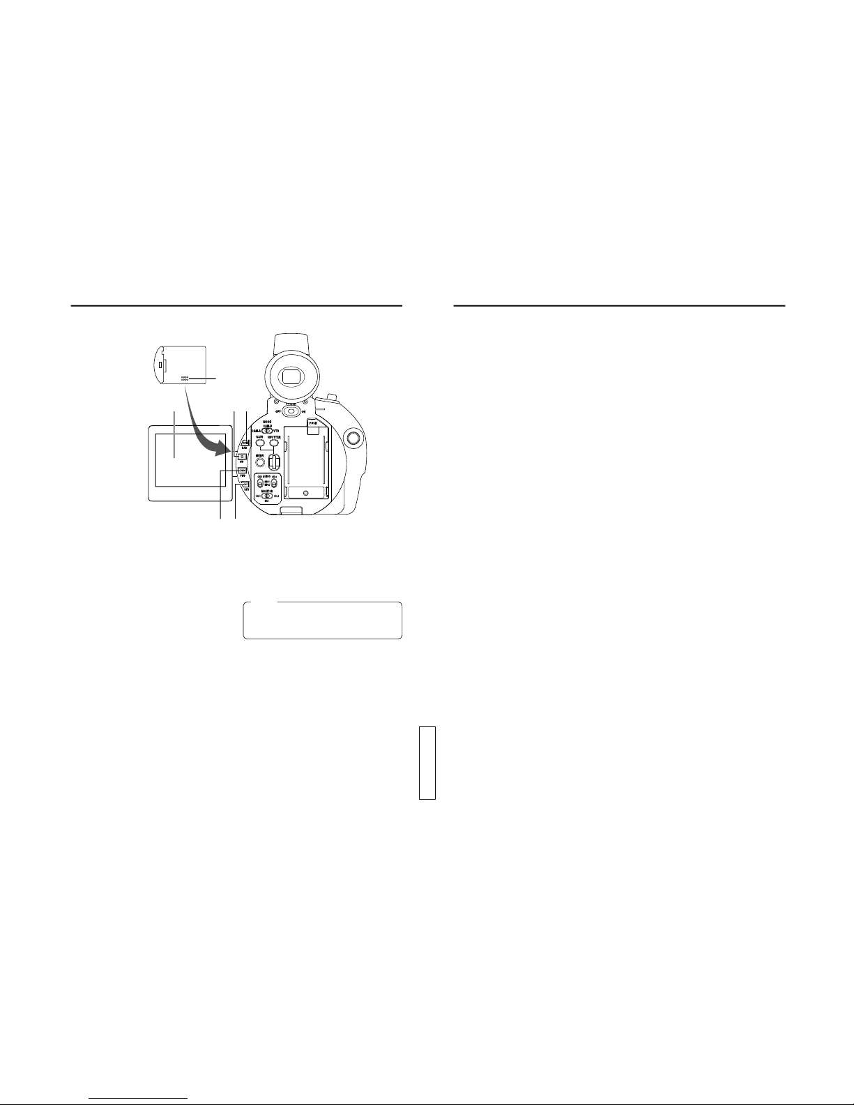
I[GAIN] Sensitivity selector button
This button is for manual adjustment of
sensitivity. It works when the AE item is set to
OFF on the OPERATION menu screen.
●WhentheAE(Auto Exposure) function is OFF
and this button is pressed, the condition of
the current gain setting is shown on the LCD
screen or the viewfinder screen for about 3
seconds. In this condition, it possible to set
the gain setting of the GY-DV300. Gain is set
by rotating the SELECT dial L. Rotating the
dial upward moves gain in the plus direction,
androtatingit downward moves it in theminus
direction.
When rotation of the dial stops, the set gain is
indicated for about 3 seconds.
[The variable range is –3 dB to +18 dB (1 dB
step)]
●Pressing the button for 1 second or more
engages the LOLUX mode.
J[SHUTTER] Shutter speed selector button
This button is for manual adjustment of the
shutter speed.
●Itworks when theAEitemon the OPERATION
menu screen is set to OFF. Using the
SHUTTER item on the OPERATION menu
screen, select the shutter speed mode as
STEP or VARIABLE.
Set to VARIABLE when shooting computer
display screens.
●Whenthe button is pressedinMANUALmode,
the current shutter speed setting is shown on
the LCD screen or the viewfinder screen for
about 3 seconds. In this condition, it possible
tosetthe shutter speed of the GY-DV300. The
shutter speed is set by rotating the SELECT
dial L. When rotation of the dial stops, the
set shutter speed is indicated for about 3
seconds.
[Variable range (U MODEL)
STEP: 1/60, 1/100, 1/250, 1/500, 1/1000,
1/2000
VARIABLE: 1/60.1 to 1/2084.6]
[Variable range (E MODEL)
STEP: 1/50, 1/120, 1/250, 1/500, 1/1000,
1/2000
VARIABLE: 1/50.1 to 1/2067.8]
K[MENU] Menu button
Pressthisbutton for 1 second or more to display
the MENU setting screen. The MENU setting
screen is shown on the LCD screen and the
viewfinder screen.
Whenthe OUTPUTCHAR. item ontheDISPLAY
[2/2] menu screen is set to MIX, the MENU
setting screen can also be output for display via
the VIDEO OUT or Y/C OUT connector.
Selections and settings in the menu are
performed with the SELECT dial L.
The normal screen returns when this button is
pressed while the MENU setting screen is
displayed.
LSELECT dial
●When gain and shutter adjustment is set to
the MANUAL mode, this dial is rotated to set
the gain or shutter speed.
●When the white balance adjustment is set to
theMANUALmode,thewhitebalance setting
mode can be selected by rotating this dial.
[Variable range: PRESET, MEMORY 1, 2, 3]
●When the MENU setting screen is displayed,
this dial is used to select and set items in the
menu.
To confirm menu items and set values, press
the dial.
M[CH-1/CH-2 AUDIO] CH-1/CH-2 audio input
selector switch
Usedtoselecttheaudiosource input to the CH-
1/CH-2 channel. Separate inputs can be
selected for the CH-1/CH-2 channels.
MIC 1: The sound from the built-in microphone
or from the MIC 1 input connector is
input. Select the input from the built-in
microphone or from the MIC 1 input
connector with the MIC1 INPUT SEL
itemonthe SYSTEM [1/2] menu screen.
MIC 2: The sound from the MIC 2 input
connector is input.
N[MONITOR] Audio monitor selector switch
Selects the monitor sound heard from the
EARPHONE jack Xor the built-in speaker.
CH-1 : CH-1 audio signal
CH-2 : CH-2 audio signal
MIX : MixedsignalconsistingoftheCH-1and
CH-2 audio signals.
14
CONTROLS,
INDICATORS AND CONNECTORS
Rear Section
POWER
OFF ON
MODE PUSH
CAM-B
VTR
SHUTTER
MENU
AUDIO
MONITOR
MIC1
MIC2
CH-2CH-1
CH-2
MIX
CH-1
GAIN
CAM-A
BAR
AW
FWD
REV
!3
!5
!4
!6
!7
@0
!9
!8
@4@3@2
@1
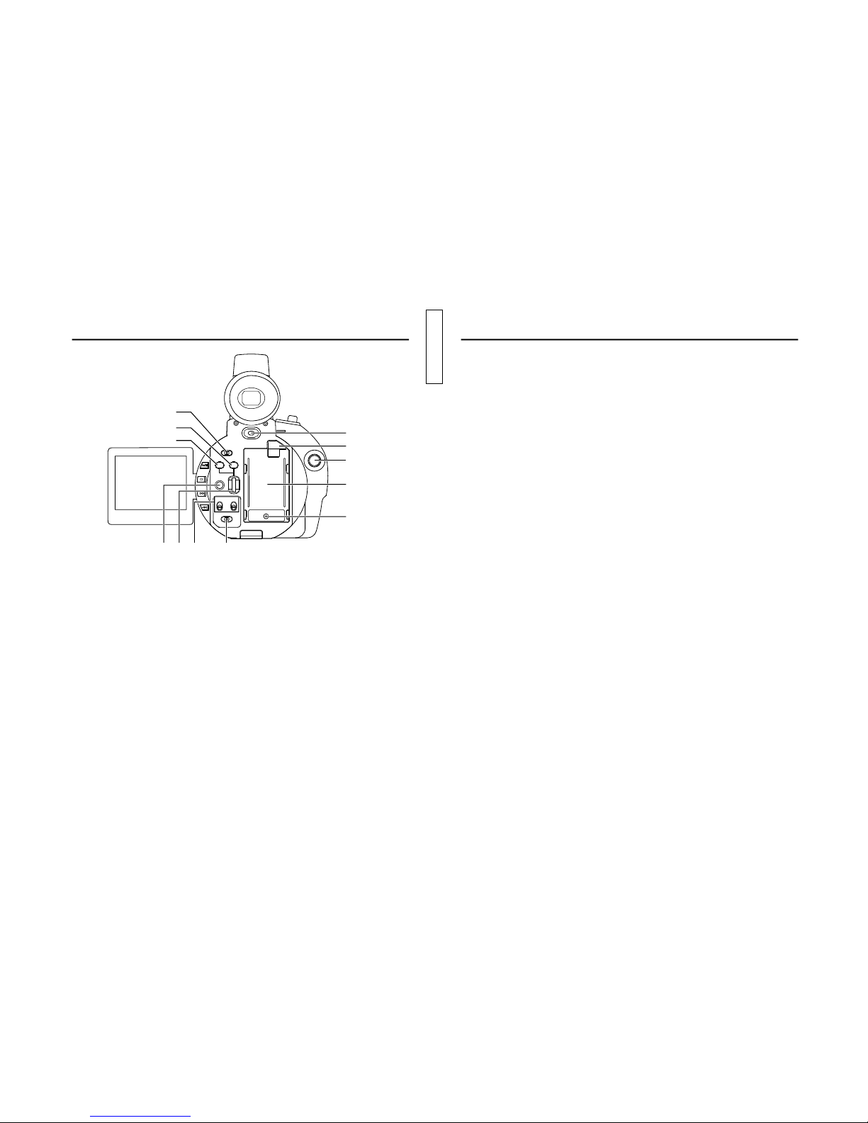
C[POWER] POWER switch
Turn the power ON and OFF with this switch.
DBattery holder (U MODEL)
Mounttheprovided battery pack BN-V428 here.
(
☞
See page 34.)
DBattery holder (E MODEL)
Mountthe optional battery pack BN-V416orBN-
V428 here. (
☞
See page 34.)
TheBN-V416 battery pack cannotbeused when
the optional Network Pack KA-DV300 is used.
EBattery lock release button
Press this button to remove the battery pack.
F[DC INPUT] DC connector
Power input connector for 7 V DC.Accepts the
optional AC adapter AA-P30. The power range
is 6 V to 12 V.
GREC Start/Stop button
This button starts and stops recording. When
theGY-DV300 is in the shootingmode,pressing
this button starts the recording. Pressing the
button during a recording engages the
recording-pause (standby) mode.
H[MODE] Mode selector switch
Set in accordance with the operating mode of
theGY-DV300.Whenused intheshooting mode,
the switch is set to “CAM-A”or “CAM-B”. When
used in the VTR playback mode, it is set to
“VTR”. When set to “CAM-A”or “CAM-B”in the
shooting mode, two separate sets of setting
values for recording can be set by means of the
menu screens.
“CAM-A”: In this position, shooting takes
place in accordance with the
conditions set for “CAM-A”on the
menu screen.
“CAM-B”: In this position, shooting takes
place in accordance with the
conditions set for “CAM-B”on the
menu screen.
“VTR”: Setto this positionwhenperforming
VTR playback.
Also set to this position to record
the video signal input from the DV

TENTATIVE
17
●Pressing this button simultaneously with the
REVbutton Rduring stopinthe VTR playback
mode initiates the blank search mode (for
locating the end point of recordings).
R[REV] REVERSE/REW button
●Pressing this button in the shooting mode
engages playback in reverse direction at
normal speed for as long as the button is
pressed. When the button is released, the
recording-standby mode is engaged.
●Pressingthis button intheVTR playback mode
during stop or fast forward operation initiates
the rewind mode. Pressing this button during
playback, still picture playback, or forward
search initiates reverse search.
SLCD monitor screen
●Shows a color camera image or the VTR
playback picture.
It is also used for displaying the following:
•Menu setting screens
•Characters showing the whether the GY-
DV300 is set to shooting mode or VTR
playback mode
•Date and time and time code
•Audio level meter
•Warning indications, etc.
For details,
☞
see page 22.
•The angle of the LCD screen can be rotated
tomake the LCD screenfacetoward the lens
or downward.
•The brightness and color saturation can be
adjustedand set on the DISPLAY[1/2] menu
screen.
TBuilt-in speaker
OutputstheVTRplayback sound.Theplayback
soundlevel is adjusted with theZOOM/Playback
sound level adjustment lever a. The monitor
sound is not output in the shooting mode. The
audio from the loudspeaker is not output when
an earphone is plugged into the EARPHONE
jack X. (
☞
See page 82.)
16
CONTROLS,
INDICATORS AND CONNECTORS
Rear Section (cont’d)
@8
@5
@7
@9 @6
#0
O[BAR] Color bar/Playback & still button
●Pressing this button in the shooting mode
switches the setting between color bar output
and camera image output.
●Pressingthis button intheVTR playback mode
starts playback. Pressing this button during
playback engages the playback mode.
●Pressingthisbuttonduring playback engages
the still picture mode.
P[AW]White balance/Stop button
●Used when white balance adjustment is
performed in the shooting mode.
To use this button for white balance
adjustment,the WHITE BALANCE item onthe
OPERATION menu screen should be set to
PUSH AUTO.
Whenthisbuttonispressed, the current white
balance setting mode is displayed for about 3
seconds on the LCD screen or the viewfinder
screen after which white balance adjustment
of the GY-DV300 becomes possible.
The white balance adjustment setting mode
is selected by rotating the SELECT dial L.
When rotation of the dial stops, the selected
LCD door storage
compartment
settingmode is displayed for about3seconds.
When the button is then pressed for 1 second
or more, the white balance adjustment starts.
[Variable range: PRESET, MEMORY 1, 2, 3]
Memo:
The PRESET mode is fixed at 3200 K (colour
temperature).Even if theAWbutton is pressed,
white balance adjustment is not performed.
●Pressingthis button intheVTR playback mode
engages the Stop mode.
[FWD] FORWARD/FF button
●Pressing this button in the shooting mode
engages playback in forward direction at
normal speed for as long as the button is
pressed. When the button is released, the
recording-standby mode is engaged.
●Pressingthis button intheVTR playback mode
during stop or rewind operation initiates the
fastforwardmode. Pressing this button during
playback, still picture playback, or reverse
search initiates forward search mode.

TENTATIVE
19
The playback sound from the built-in speaker is
not output when an earphone is plugged into
this jack.
Y[DV] DV connector (U MODEL)
Using a DV cable (optional), a digital video
componentwith DV connector canbeconnected
here.
To record DV signals (IEEE1394 signals) from
this connector, the MODE switch Hshould be
set to “VTR”.
Y[DV] DV connector (E MODEL)
Using a DV cable (optional), a digital video
componentwith DV connector canbeconnected
here.
Thisconnector is usedforoutput of the DVsignal
or input the VCR contorl signal from the digital
video component with DV connector.
The use this connector, set the MODE switch
Hto “VTR”.
ZCassette cover
Sliding the EJECT switch located on the top
section opens this cover to allow insertion or
removal of the videocassette. The cover locks
into place when it is closed after the cassette
holder has been properly locked. (
☞
See page
38.)
[Microphone holder attachment base
Usefor attaching an optionalmicrophoneholder.
Attach the optional microphone holder KA-A33
here. (
☞
See page 36.)
Memo:
•When inserting a cassette, push the “PUSH
HERE”section on the cassette holder to lock
the cassette holder correctly, and then close
the cassette cover.
•To prevent foreignmatterfrom penetrating into
the interior of the GY-DV300, never leave the
unit with this cover left open.
•The GY-DV300 does not function if the
cassette cover is not closed.
Memo:
The GY-DV300 is not capable of recording DV
signals (IEEE1394 signals).
18
CONTROLS,
INDICATORS AND CONNECTORS
Left Side Section
U[VIDEO OUT]Video output connector (RCA)
Output connector for composite video signal.
Outputs the input video signal and playback
picture.
●When the OUTPUT CHAR. item on the
DISPLAY [2/2] menu screen is set to MIX, on-
screen-indicatorslike those shown ontheLCD
monitorscreencan be output (black and white
display).
●When the SETUP item on the SYSTEM [2/2]
menu screen is set to ON, signals with setup
information can be output. (black and white
display) (U MODEL)
V[Y/C OUT]Y/C video output connector (4-pin)
Separate YC video signal output connector.
Outputs the input video signal and playback
picture.
●When the OUTPUT CHAR. item on the
DISPLAY [2/2] menu screen is set to MIX, on-
screen-indicatorslike those shown ontheLCD
monitorscreencan be output (black and white
display).
●When the SETUP item on the SYSTEM [2/2]
menu screen is set to ON, signals with setup
information can be output. (black and white
display) (U MODEL)
●When theASPECT item is set to LETTER on
the SYSTEM [2/2] menu screen, an ID signal
for identifying the wide-screen aspect is
output.
W[CH-1/CH-2 LINE OUT] CH-1/CH-2 audio
output connector (RCA)
Output connector for audio signal. In the
shooting mode the input audio signal is output.
In the VTR mode the playback sound is output.
X[EARPHONE] Earphone jack
This is a jack for connecting an earphone for
monitoring the sound. Plug in an earphone or
headphone with a 3.5 mm diameter plug.
Monaural sound is output.
Select the output sound with the MONITOR
switch N. The volume of the monitor sound in
the shooting mode is set with the EARPHONE
LEVEL item on the TOP MENU screen.
MIC 2 IN
MIC 1 IN
Y/C OUT
VIDEO OUT
LINE
OUT
CH-1CH-2
EARPHONE
DV
#7
#1
#5
#2
#6 #3
#4

TENTATIVE
21
CONTROLS,
INDICATORS AND CONNECTORS
Top Section
aZOOM/Playback sound level adjustment
lever
●This works as the zoom lever in the shooting
mode. Pressing the lever in the T direction
narrows the lens angle perspective for
telephoto shots.
Pressing it in the W direction increases the
angle of the lens for a wider shooting angle.
The harder the lever is pressed, the quicker
the zoom action.
●In the VTR playback mode, this lever is used
foradjusting theplayback soundlevel.Pressing
the lever in the + direction increases the
volume level, and pressing in the - direction
decreases the level.
b[EJECT] Eject switch
Slide to the side when inserting or ejecting the
videocassette. Sliding this button and then
opening the cassette cover will eject the
cassette.
c[ZOOM] Zoom lever
Lever for zoom operation from the handle top
section.
●In the shooting mode, pressing this lever in
the T direction narrows the lens angle
perspective for telephoto shots.
Pressing it in the W direction increases the
angle of the lens for a wider shooting angle.
Thezoomspeed of this zoom lever isselected
withthe HANDLE ZOOMitemon the SYSTEM
[2/2] menu screen.
d[START/STOP] REC START/STOP button
Button for start and stop of recording from the
handle top section.
When the GY-DV300 is in the shooting mode,
pressing this button starts the recording.
Pressingthebuttonduringarecording engages
the recording-standby mode.
W
W
T
T
VOLUME
EJECT
START/
STOP
$3
$4
$2
$1
20
Memo:
•The audio input channel is selected with the
CH-1/CH-2 audio input selector switch M.
•To reduce the wind noise of the microphone,
set the WIND CUT MIC1/MIC2 item on the
SYSTEM [1/2] menu screen to ON.
CONTROLS,
INDICATORS AND CONNECTORS
Front Section
\Built-in microphone
Built-in monaural microphone.
●To use this microphone, set the MIC1 INPUT
SEL item to INT on the SYSTEM [1/2] menu
screen.
][MIC 1] Microphone 1 input connector (XLR-
3P)
Connect an external microphone to this
connector. Monaural signals are recorded.
●To use the microphone connected to this
connector, set the MIC1 INPUT SEL item to
XLR on the SYSTEM [1/2] menu screen.
●To use a microphone requiring +48 V power
supply (phantom microphone), set the +48V
MIC1itemonthe SYSTEM [1/2] menu screen
to ON. This connector will then supply +48 V
DC current.
When using a microphone other than a
phantommicrophone,set the +48V MIC1 item
to OFF.
`[MIC 2] Microphone 2 input connector (XLR-
3P)
Connect an external microphone to this
connector. Monaural signals are recorded.
●To use a microphone requiring +48 V power
supply (phantom microphone), set the +48V
MIC2itemonthe SYSTEM [1/2] menu screen
to ON. This connector will then supply +48 V
DC current.
When using a microphone other than a
phantommicrophone,set the +48V MIC2 item
to OFF.
\
]
`

TENTATIVE
23
Normal display in the shooting mode
qw
e
r
t
y
No. Item Contents
1Zoom ratio (Characters, Displayed during zoom operation. The characters indicate the wide-
numeric value) angle(W)and telephoto(T) zoompositions.The numeric valueindicates
the approximate zoom ratio.
2Time code display Shows the time code (hours, minutes, seconds, frames).
Whether this should be displayed can be selected by setting the TIME
CODE item on the DISPLAY [2/2] menu screen.
3Recording time mode Shows the recording speed at the time of the recording.
indication SP : Standard Play mode
LP : Long Play mode
When the remaining tape indication is OFF, this indication is shown at
the 4position.
4Remaining tape time Indicates the remaining tape amount (minutes) in 1-minute steps.
indication WhetherthisindicationshouldbeONor OFF can be selected by setting
the TAPE REMAIN item on the DISPLAY [2/2] menu screen.
* The indication may not appear when a new tape is loaded, after the
tape runs, the indication appears.
5Remaining battery The remaining battery power is indicated by four different indicators.
power indication
6Camera-shake Displayed when the camera-shake compensation function is on (OIS
compensation on item on the OPERATION menu screen is set to ON).
indication
Blinking indicator
(no remaining
battery power)
Fully charged
battery
22
CONTROLS,
INDICATORS AND CONNECTORS
In addition to the E-E picture and the playback picture, the following indications are displayed on the LCD
screen and the viewfinder screen.
Status screens (screens for use in checking the current camera settings)
Event indications
Alarm indications
Menu setting screens
Auto white balance operation indicator
When the LCD screen is used, the above indicators are not shown on the viewfinder screen.
When the LCD screen is faced toward the viewfinder screen side and the LCD door is closed, the above
indictors appear on the viewfinder screen.
Status Screens
The contents of the status screens differ in the camera shooting mode and in the VTR playback mode.
Also, the items displayed on the status screen differ with the direction that the LCD screen is facing, i.e.,
toward the viewfinder (normal display) or toward the lens (vertically inverted display).
Normal display in the shooting mode
For a part of the status indicators it is possible to
select whether or not the item should be displayed
by making a selection on the DISPLAY [2/2] menu
screen.
Vertically inverted display in the shooting mode
In relation to the normal display, the vertically
inverted display is reversed left to right, and only
thebattery symbol and the recordingsymbol/pause
symbol are displayed.
●When the LCD screen is faced toward the lens
side and the LCD door is closed, the normal
display will be seen.
Battery symbol
VTR operation symbol
(Recording or pause)
Indications on LCD Screen
and Viewfinder Screen
Memo:
After-images will increase on the LCD screen when used under cold circumstances.

TENTATIVE
25
No. Item Contents
AShooting mode Indicates whether the shooting mode isAUTO or MANUAL.
indication Å: Displayed when the shooting mode is AUTO (when the MODE item
is set to AUTO on the TOP MENU screen).
˜: Displayed when the shooting mode is MANUAL (when the MODE
item is set to MANUAL on the TOP MENU screen).
BFilter indication ND: Displayed when the ND filter switch is set to ON.
CIris F-value indication Indicates the F-value of the lens in the manual iris adjustment mode
(when the IRIS item is set to MANUAL on the OPERATION menu
screen). The indications are:
F1.6, F2, F2.8, F4, F5.6, F8, F11, F16. CLOSE
DIris compensation –3 ~ ±0 ~ +3: Indicates the compensation value set with the iris
value indication adjustment dial in the auto iris mode.
M: Displayed in the manual iris adjustment mode.
EVTR mode indicators STBY: Recording-standby mode
REC: During recording
ED.FWD: During playback in forward direction
ED.REV: During playback in reverse direction
STOP: Tape protect mode
EJECT: During cassette ejection
–––: Tape is not loaded
FFade indication Displayed when the fade function is ON (when the FADER item is set to
BLACK on the SYSTEM [2/2] menu screen).
BK : Displayed when the FADER item is set to BLACK. (Fade-in and
fade-out from black screen.)
GAudio sampling 32K: Displayed when the AUDIO MODE item is set to 32K on the
frequency indication SYSTEM [1/2] menu screen. (Audio is recorded with 12-bit, 32
kHz sampling.)
48K: Displayed when the AUDIO MODE item is set to 48K on the
SYSTEM [1/2] menu screen. (Audio is recorded with 16-bit, 48
kHz sampling.)
HAudio level meter Indicates the audio levels of CH-1, CH-2.
display These meters are not shown when the AUDIO LEVEL item is set to
OFF on the DISPLAY [2/2] menu screen.
IDate and time Shows the date and time.
indication The indication is enabled/disabled by selecting the TIME/DATE item on
theDISPLAY[2/2] menu screen. The display style is selected by setting
the DISP STYLE item.
When the date and time are not set, the indication will be as follows.
––/ ––/ ––
––: ––: ––
24
No. Item Contents
7
Manual focus indication
MF: Displayed when manual focusing is enabled (when the FOCUS
switch is set to MANUAL).
8
Manual shutter mode
S: Displayed in the manual shutter mode (when the AE item is set to
indication
OFF on the OPERATION menu screen).
This indication is not shown when the shooting mode is AUTO or the
AE item is set to ON.
It is not shown when the shutter is NORMAL (1/60 (U MODEL)/1/50 (E
MODEL)) or gain is set to ALC.
9Manual gain mode Indicated in the manual gain setting mode (when the AE item is set to
indication OFF on the OPERATION menu screen).
6 dB: The gain value is indicated for anything but 0 dB, LOLUX, or ALC.
L: Displayed in LOLUX mode.
The indication is not shown when the gain setting is 0 dB or ALC.
It is not shown when the shooting mode isAUTO, or theAE item is set
to ON.
0Manual white balance Displayed when manual white balance adjustment is enabled (when
mode indication the WHITE BALANCE item is set to PUSHAUTO on the OPERATION
menu screen).
Indicates the white balance setting mode.
WBP: White Balance Preset mode (fixed at a colour temperature of
3200 K. Manual white balance adjustment is inhibited.)
WB1: White Balance memory 1 mode
WB2: White Balance memory 2 mode
WB3: White Balance memory 3 mode
WhenWB1,WB2 or WB3 is indicated,manualwhitebalance adjustment
is enabled. The result of the white balance adjustment is retained in the
indicated memory.
It is not shown when the shooting mode is AUTO, or when the WHITE
BALANCE item is set to AUTO.
!4
i
u
o
!0
!1
!2
!5
!3
!6 !7 !8 !9
CONTROLS,
INDICATORS AND CONNECTORS
Indications on LCD Screen and
Viewfinder Screen (Cont’d)

TENTATIVE
27
VTR playback mode/IEEE1394 recording mode status indications
VOL.
DV
PLAY
qw
e
r
t
No. Item Contents
1Audio playback volume Displayed in the VTR mode. Characters indicate the high and low of
indication the playback volume.
2Time code indication The recorded time code data (hours, minutes, seconds, frames) are
shown here in the playback mode.
Theindicationis turned ON/OFF by setting theTIME CODE item on the
DISPLAY [2/2] menu screen.
3Recording/playback Themodeinwhichthetapewasrecordedisdisplayedduringplayback.
speed mode indication SP: Standard Play mode
LP: Long Play mode
When the remaining tape time indication is set to OFF, this indication is
shown at the position indicated by 4.
4Remaining tape time Indicates the remaining tape time in 1-minute steps.
indication The indication is turned ON/OFF by setting the TAPE REMAIN item on
the DISPLAY [2/2] menu screen.
* The indication may not appear when a new tape is loaded, after the
tape runs, the indication appears.
5Remaining battery The remaining battery power is indicated by four different indicators.
power indication
Blinking indicator
(no remaining
battery power)
Fully charged
battery
26
Vertically inverted display indications in the shooting mode
Remaining battery power indication
The remaining battery power is indicated by four
different indicators.
: Fully charged battery
: Remaining battery power is low
: No remaining battery power
(blinking)
VTR operation mode indication
● symbol: During recording
wsymbol: In recording-standby mode
CONTROLS,
INDICATORS AND CONNECTORS
Indications on LCD Screen and
Viewfinder Screen (Cont’d)

TENTATIVE
29
Event Indications
Whenthegain and shutter speed are changed manually,the set condition is displayed forabout3seconds
at the time the change is made.
Event display area
Event display area
Set Condition Contents of Indication
When the gain value is changed GAIN –3 dB to 18 dB (1 step)
When the LOLUX gain mode is selected LOLUX
When the shutter speed is changed SHUTTER 1/100, 1/250.1/500,1/1000, 1/2000
(U MODEL)
1/120,1/250. 1/500, 1/1000, 1/2000
(E MODEL)
When the variable shutter speed is changed V.SHUTTER 1/60.1 - 1/2084.6 (U MODEL)
1/50.1 - 1/2067.8 (E MODEL)
When the shutter is NORMAL (shutter speed: 1/60)
SHUTTER NORMAL
28
No. Item Contents
6VTR mode indication Indicates status of VTR operation.
(STOP, PLAY, FF, REW, EJECT, STBY, FWD, REV, BSRH)
7DV signal indication DV : Displayed when IEEE1394 signal is recorded from the DV
(U MODEL) connector.
8Audio sampling The audio sampling frequency by which the recording was made is
frequency indication displayed during playback. (32K, 48K, 44.1K)
9Audio level meters The playback audio level meters are displayed during playback.
display These are not shown when the AUDIO LEVELitem is set to OFF on the
DISPLAY [2/2] menu screen.
0Date and time Recorded data is show during playback, fast forward and rewind
indication operations.
During recording, the data from the DV connector is shown.
The current data is shown in the stop mode.
The indication is enabled/disabled by selecting the TIME/DATE item on
theDISPLAY[2/2] menu screen. The display style is selected by setting
the DISP STYLE item.
When the date and time are not set, the indication will be as follows.
––/ ––/ ––
––: ––: ––
VOL.
DV
PLAY
yuio!0
CONTROLS,
INDICATORS AND CONNECTORS
Indications on LCD Screen and
Viewfinder Screen (Cont’d)
(U MODEL)

TENTATIVE
31
MENU Setting Screen
Used for making a variety of settings. See “MENU
Setting Screen”on page 86.
AUTO WHITE and the result of the operation are
displayedwhentheautowhite balance adjustment
is performed.
See“AutoWhiteBalanceAdjustment”onpage66.
AUTO WH I TE
OPERATION
MODE MENU MALA
10NU
SYSTEM SET ..
EARPHONELVELE
DISPLAY SET. .
CAMERA SET [CA -
-
MA.
.
OPERAT ION[CA
M.A] .
CLOC K/ TC..
MENU ALLR
ESET CELANC
EXIT
]
AutoWhite Balance Indication
30
Alarm indications
Alarm indications are displayed under the following circumstances. The warning messages are shown
blinking.
•When remaining battery power or remaining tape is low.
•Improper operation attempted.
•Abnormality generated in the GY-DV300.
Warning indication area
Warning Indication Contents
TAPE NEAR END Displayed when the remaining tape is 3 minutes or less in the shooting
mode. It is not shown in the playback mode.
TAPE END Displayed when the tape has run out.
TAPE BEGIN Displayed when the tape is at the beginning position.
LOWVOLTAGE Displayed when remaining battery power becomes low.
CLOSE CASSETTE COVER!
Displayedwhenoperation is attempted while the cassette cover isopen.
NOTAPE Displayedwhen no videocassette is insertedandtheVTRtriggerbutton
is pressed.
REC INHIBIT Displayedwhenanunrecordablevideocassette(the switch on the back
of the cassette is set to “SAVE”) is loaded.
1394 INHIBIT (U MODEL) Displayed if an attempt to record is made when no DV signal is input.
COPY INHIBIT Displayed whenattemptto record acopy-guardprotected signal is made.
CASSETTE COVER OPEND!
Displayed when the cassette cover was opened during recording.
CASS.CARRIAGE UNLOCK
Displayed when the cassette cover is closed but the cassette holder is
not locked.
VTR WARNING [DEW] Displayed when condensation occurs in the unit.
HEAD CLEANING Displayed in case of video head clogging.
REQUIRED!
VTR WARNING (HARD) Lights when abnormality occurs in the unit.
VTR WARNING(TAPE) Displayed when the tape is cut.
CONTROLS,
INDICATORS AND CONNECTORS
Indications on LCD Screen and
Viewfinder Screen (Cont’d)

TENTATIVE
E-32
PROFESSINAL
DVCAMCORDER GY-DV300
IRIS
AUDIO
LEVEL
CH-1 CH-2
NDFILTER
ON
OFF
FOCUS
AUTO
PUSH
AUTO
MANU
OPEN
PREPARATIONS Basic System
MICROPHONE
MV-P615 MIC HOLDER IEEE1394 CABLE
4P
IEEE1394 CABLE
4P
4P
6P
NETWORKPACK
KA-DV300 PC
VIDEO LIGHT
TELE CONVERSION LENS
WIDE CONVERSION LENS
DVCAMCORDER
TRIPOD
ACADAPTER/
BATTERYCHARGER
AA-P30
RECHARGEABLE
BATTERYPACK
BN-V416
AC
BATTERYPACK
(Large-capacity)
BN-V428
32
PROFESSINAL
DVCAMCORDER GY-DV300
IRIS
AUDIO
LEVEL
CH-1 CH-2
NDFILTER
ON
OFF
FOCUS
AUTO
PUSH
AUTO
MANU
OPEN
PREPARATIONS Basic System
MICROPHONE
MV-P615 MIC HOLDER IEEE1394 CABLE
4P
IEEE1394 CABLE
4P
4P
6P
NETWORKPACK
KA-DV300 PC
VIDEO LIGHT
TELE CONVERSION LENS
WIDE CONVERSION LENS
DVCAMCORDER
TRIPOD
ACCESSORYKIT
ACADAPTER/BATTERY
CHARGER
AA-P30
RECHARGEABLE
BATTERYPACK
BN-V428
AC
U
E

TENTATIVE
34
Battery pack
Connector
Battery Pack Operation
PREPARATIONS
Power Supply Preparation (cont’d)
Use the provided battery pack BN-V428 for battery pack operation. (U MODEL)
Use the optional battery pack BN-V416 or BN-V428 for battery pack operation. (E MODEL)
The BN-V416 battery pack cannot be used when the optional Network Pack KA-DV300 is used. (E MODEL)
Beforeuse the battery packshouldbe charged using
the provided AC Adapter/Charger AA-P30.
1.
Plug the AC cable of the AC Adapter/Charger
intoanAC outlet.The POWER lampilluminates.
2.
While pushing the battery pack down, slide it
in the direction of the arrow to mount it on the
AC Adapter/Charger. Charging starts, and the
CHARGElampblinksgreen.Itchanges to light
steadily when charging is completed.
3.
When charging is completed, remove the
battery by sliding it in the opposite direction of
the mounting direction.
*
For details, see the instruction manual for theAA-P30.
Charging the Battery Pack
POWER lamp
Battery
pack
AC cord
AC outlet
AA-P30
CHARGE lamp 1
Ifthe DC cableis connected to theGY-DC300,
unplug the cable.
1.
Hold the battery pack with the connector side
facing the GY-DC300.
2.
Whilepressing the battery pack against theGY-
DC300,slideitdownward to attach it to the GY-
DV300.
Attaching the Battery Pack on the GY-DV300
Ensure that the POWER switch on the GY-
DV300 is set to OFF.
1.
While pressing the battery lock release button,
slide the battery pack upward to remove it.
Detaching the Battery Pack from the GY-DV300
Battery lock
release button CAUTION:
Do not detach the battery pack while recording
is taking place.
CHARGE lamp 2
33
AC Operation
Usetheprovided (UMODEL)/optional(E MODEL)ACAdapter/ChargerAA-P30 as theAC power supply.
The DC INPUT connector on the GY-DV300 accepts power voltage in the range of DC 6V to DC 12V.
PREPARATIONS
Power Supply Preparation
The GY-DV300 is operable with AC power supply or battery pack.
To AC outlet
DC INPUT
connector
POWER lamp
DC cable
AC cord
AA-P30
DC OUTPUT
connector
Set the POWER switch on the GY-DV300 to OFF.
If a battery pack is attached to the unit, detach the battery pack.
1.
Plug one end of the DC cable provided with theAC Adapter/Charger into the DC INPUT connector of
the GY-DV300, and then connect the other end to the DC OUTPUT connector on the AC Adapter/
Charger.
2.
Plug the AC cable of the ACAdapter/Charger into anAC outlet. The POWER lamp illuminates when
power is supplied to the AC Adapter/Charger.
* For details, see the instruction manual for the AA-P30.
CAUTION:
●Do not disconnect or connect the DC cable or AC cord while recording is taking place.
●Remaining battery power indication when the AC adapter is used
WhentheoptionalNetworkPack KA-DV300 is connected, the remaining battery power
indication for fully charged battery may not be displayed.
POWER switch
Fully charged

TENTATIVE
36
Screw
hole
PREPARATIONS
Attaching the Microphone (optional)
Using the optional KA-A33 microphone holder allows the optional microphone MV-P615U (phantom
microphone) to be attached.
Mount the microphone holder on the microphone holder attachment base on the handle of the GY-
DV300.
MIC 1
MIC 2 IN
MIC 1 IN
Y/C OUT
VIDEO OUT
LINE
OUT
CH-1CH-2
EARPHONE
DV
Handle Microphone holder
attachment base
Knob Microphone
holder
Attachment
screw
Attachment
base
MIC 2
How to Attach
1.
Mount the microphone holder on the
microphone holder attachment base on the
handle of the GY-DV300.
1Loosen the attachment screw on the
microphone holder.
2Fasten the attachment screw on the
microphone holder to secure the holder to
theGY-DV300.
2.
Turn the knob on the microphone holder
anticlockwise to loosen it and open the
microphone holder.
3.
Placethe microphone in themicrophoneholder.
Place the microphone toward the front to
prevent it from interfering with the cassette
cover.
4.
Turn the knob on the microphone holder
clockwise to secure the microphone.
5.
Connect the microphone cable to the MIC 1 or
MIC 2 input connector on the GY-DV300.
6.
Makesureto perform the correct setting for use
of a phantom microphone. (
☞
See page 50.)
Memo:
Whenusing a microphone connectedtothe MIC
1input connector,set the MIC1INPUTSELitem
to XLR on the SYSTEM [1/2] menu screen.
35
Battery Pack Operation (Cont’d)
Remaining Battery Power Indication
Fully
charged
TALLY lamp
LCD screen
Remaining battery
power indication
The remaining battery power condition can be
checked by the remaining battery power indication
on the LCD screen and the TALLY lamp.
Thebattery condition is indicatedasshown in the table
below. Prepare for battery pack replacement in
accordance with the indications.
Indication
LCD Screen
Tally Lamp
—
Afterthe no remaining batterypowerwarning appears,
the GY-DV300 automatically stops operation if the
battery power operation is continued.
Remaining battery
power is low.
Prepare or replace
with a fully charged
battery pack.
Blinking
No remaining bat-
tery power.
Immediately replace
with a fully charged
battery pack.
Slow blinking
(1 blink per
second)
OperatingTime with Battery Pack
When a fully charged battery pack is attached, the
approximate continuous operating time is as shown
in the table on the left.
●Battery operating time may differ depending on the
number of times the battery has been charged,
chargingconditionsand the operating environment,
etc. Regard the values in the table on the left as
approximate reference times.
●Operating time is reduced in areas with a cold
environment.
●Operating time is reduced when the power zoom
lens is used frequently and when start/stop of
recording is performed frequently.
Battery
Continuous Operating Time (25°C)
Pack
WhenKA-DV300
GY-DV300 only in use
BN-V428
Approx. 120 min. Approx. 80 min.
PRECAUTIONS FORTHE BATTERY
PACK
●When the battery pack is not in use, it must be
stored in a cool, dry place.
Do not leave the battery pack in a place where
it might be subject to high temperatures (under
directsunlightin a car,etc.), as this could cause
battery leakage or shorten the service life.
●When the terminal section of the battery pack
gets dirty, the operating time will be shortened.
●If the operating time becomes greatly reduced
even immediately after recharging, the service
life of the battery pack is nearly finished.
Purchase a new battery pack.
Recharging
●Recharge the battery pack after completely
discharging it. Repeated recharging with residual
charge remaining could result in reduced battery
capacity.
●If the battery capacity is reduced by repeating
incomplete recharging, or recharging without
discharging, once discharge the battery pack
completely, then recharge it to restore the battery
capacity.
●If the battery pack is recharged with its internal
temperature raised immediately after use,
recharging may not be performed completely.
Remaining
Battery Power
After the remaining battery power indication
starts blinking, recording can be continued for
approx. 5 minutes. (when BN-V428 is used)
Other manuals for GY-DV300U - 1/3" 3-ccd Dv Camcorder
7
This manual suits for next models
2
Other JVC Camcorder manuals

JVC
JVC GZ MG37 - Everio Camcorder - 32 x Optical... Quick start guide

JVC
JVC GR-DV500US User manual

JVC
JVC GR-SXM267UA User manual

JVC
JVC Everio GZ-MG680 User manual

JVC
JVC GZ-MG26E User manual

JVC
JVC GR-D21 User manual

JVC
JVC Everio GZ-MS100 User manual

JVC
JVC Everio GZ-HD3 User manual

JVC
JVC Everio GZ-HM320 Operating and maintenance manual

JVC
JVC YU30052-572 User manual