ales
Rictal
VIDEO
CASSETTES
@The
GR-65E
employs
only
compact
video
cassettes
carrying
the
VHS-C
mark.
®Recording
onto
prerecorded
tapes
automatically
erases
the
previously
recorded
video
and
audio
signals,
An
inverted
cassette
cannot
be
inserted.
®Do
not
load
and
unlaod
the
cassette
repeatedly
without
allowing
the
tape
to
run
at
all.
This
will
stacken
the
tape
and
thereby
damage
it.
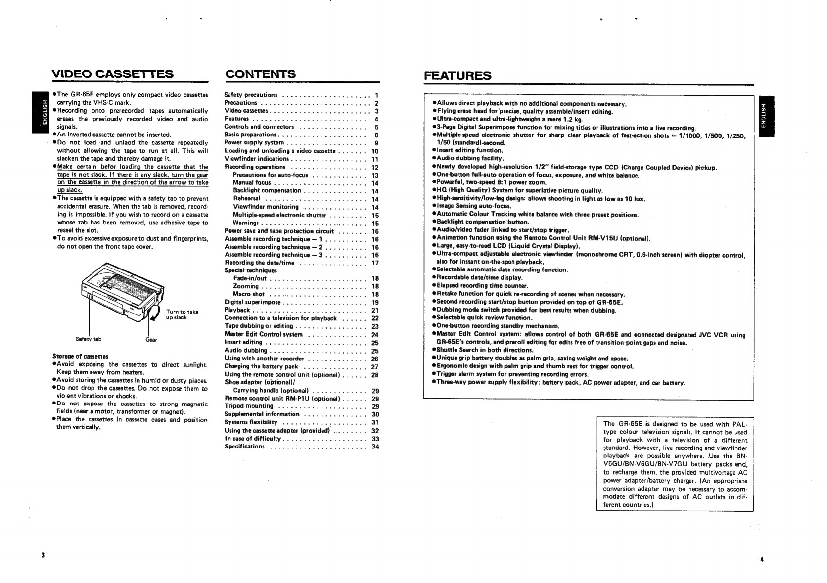
@Make
certain
befor
loading
the
cassette
that
the
tape
is
not
slack.
If
there
is
any
slack,
turn
the
gear
on
the
cassette
in
the
direction
of
the
arrow
to
take
up
slack.
©The
cassette
is
equipped
with
a
safety
tab
to
prevent
accidental
erasure.
When
the
tab
is
removed,
record-
ing
is
impossible.
If
you
wish
to
record
on
a
cassette
whose
tab
has
been
removed,
use
adhesive
tape
to
reseal
the
slot.
®To
avoid
excessive
exposure
to
dust
and
fingerprints,
do
not
open
the
front
tape
cover.
Turn
to
take
up
stack
Safety
tab
Gear
Storage
of
cassettes
®Avoid
exposing
the
cassettes
to
direct
sunlight.
Keep
them
away
from
heaters.
Avoid
storing
the
cassettes
in
humid
or
dusty
places.
®Do
not
drop
the
cassettes.
Do
not
expose
them
to
violent
vibrations
or
shocks.
®Do
not
expose
the
cassettes
to
strong
magnetic
fields
(near
a
motor,
transformer
or
magnet).
Place
the
cassettes
in
cassette
cases
and
position
them
vertically.
CONTENTS
Safety
precautions
.............
00000005
1
Precautions»...
0.2...
ce
eee
ees
2
Video
cassettes...
2.22.00...
cee
ee
eee
3
Features
55-5652
5
8
io
ek
we
EP
wees
4
Controls
and
connectors
................
5
Basic
preparations............,.-..000-
8
Power
supply
system
.........0......00005
9
Loading
and
unloading
a
video
cassette,......
10
Viewfinder
indications..................
11
Recording
operations
..................
12
Precautions
for
auto-focus
.............
13
Manual
focus
............-.-..02004
14
Backlight
compensation...............
14
Rehesreal
pissed
ad
ea
en
Bade
Se
14
Viewfinder
monitoring
...............
14
Multiple-speed
electronic
shutter
.........
15
Warnings.
.............00005
fade
ene
15
Power
save
and
tape
protection
circuit
.......
16
Assemble
recording
technique—1..........
16
Assemble
recording
technique
—2
..........
16
Assemble
recording
technique—~3..........
16
Recording
the
date/time
................
7
Special
techniques
Fade-in/out
...........
we
Sand
SAGs
18
ZOOMING
6
eco
oa
Sue
Pb
weno
ea
eae
18
Macro
shot
..
0.0...
6...
eee
ee
18
Digital
superimpose.
.................2.
19
Playback
......
ah:
OV
ESaNeh
a
hetsah
ols
etsbe
ayer
Senn:
Gea
Rees
21
Connection
to
a
television
for
playback
..,....
22
Tape
dubbing
or
editing...
...
be
ete
uviare-teette
23
Master
Edit
Control
system
..............
24
Insert
editing...
2.0...
00.0...
cee
eee
25
Audio
dubbing
.....................0.
25
Using
with
another
recorder
..............
26
Charging
the
battery
pack
..............,.
27
Using
the
remote
control
unit
(optional)...
..
.
28
Shoe
adapter
({optional)/
Carrying
handle
(optional)
.............
29
Remote
contro!
unit
RM-P1U
(optional)...
...
29
Tripod
mounting
................0.005
29
Supplemental
information
...............
30
Systems
flexibility
...........
seen
ee
nee
31
Using
the
cassette
adapter
(provided)
........
32
in
case
of
difficulty..................5.
33
Specifications
2...
20.
2...
eee
eee
34
FEATURES
©
Allows
direct
playback
with
no
additional
components
necessary.
©
Flying
erase
head
for
precise,
quality
assembie/insert
editing.
©Ultra-compact
and
ultra-lightweight
a
mere
1.2
kg.
©3-Page
Digital
Superimpose
function
for
mixing
titles
or
illustrations
into
a
live
recording.
@Multiple-speed
electronic
shutter
for
sharp
clear
playback
of
fast-action
shots
—
1/1000,
1/500,
1/250,
1/50
(standard)-second.
®Insert
editing
function.
®
Audio
dubbing
facility.
@Newly
developed
high-resolution
1/2”
field-storage
type
CCD
(Charge
Coupled
Device)
pickup.
@One-button
full-auto
operation
of
focus,
exposure,
and
white
balance.
@Powerful,
two-speed
8:1
power
zoom.
®@HQ
{High
Quality)
System
for
superlative
picture
quality.
©
High-sensitivity/low-lag
design:
allows
shooting
in
light
as
low
as
10
lux.
®@\|mage
Sensing
auto-focus.
@Automatic
Colour
Tracking
white
balance
with
three
preset
positions.
®Backlight
compensation
button.
®
Audio/video
fader
linked
to
start/stop
trigger.
®
Animation
function
using
the
Remote
Control
Unit
RM-V15U
(optional).
@Large,
easy-to-read
LCD
(Liquid
Crystal
Display).
©Ultra-compact
adjustable
electronic
viewfinder
(monochrome
CRT,
0.6-inch
screen)
with
diopter
control,
also
for
instant
on-the-spot
playback,
®Selectable
automatic
date
recording
function.
Recordable
date/time
display.
@
Elapsed
recording
time
counter.
®
Retake
function
for
quick
re-recording
of
scenes
when
necessary.
®Second
recording
start/stop
button
provided
on
top
of
GR-65E.
®@Dubbing
mode
switch
provided
for
best
results
when
dubbing.
Selectable
quick
review
function.
®@One-button
recording
standby
mechanism.
®Master
Edit
Control
system:
allows
control
of
both
GR-65E
and
connected
designated
JVC
VCR
using
GR-65E’s
controls,
and
preroll
editing
for
edits
free
of
transition-point
gaps
and
noise.
®@Shuttle
Search
in
both
directions.
®@Unique
grip
battery
doubles
as
palm
grip,
saving
weight
and
space,
@Ergonomic
design
with
palm
grip
and
thumb
rest
for
trigger
control.
©Trigger
alarm
system
for
preventing
recording
errors.
Three-way
power
supply
flexibility:
battery
pack,
AC
power
adapter,
and
car
battery.
The
GR-65E
is
designed
to
be
used
with
PAL-
type
colour
television
signals.
It
cannot
be
used
for
playback
with
a
television
of
a
different
standard.
However,
live
recording
and
viewfinder
playback
are
possible
anywhere.
Use
the
BN-
V5GU/BN-V6GU/BN-V7GU
battery
packs
and,
to
recharge
them,
the
provided
muiltivoitage
AC
power
adapter/battery
charger.
(An
appropriate
conversion
adapter
may
be
necessary
to
accom-
modate
different
designs
of
AC
outlets
in
dif-
ferent
countries.)
$$$
ENGLISH