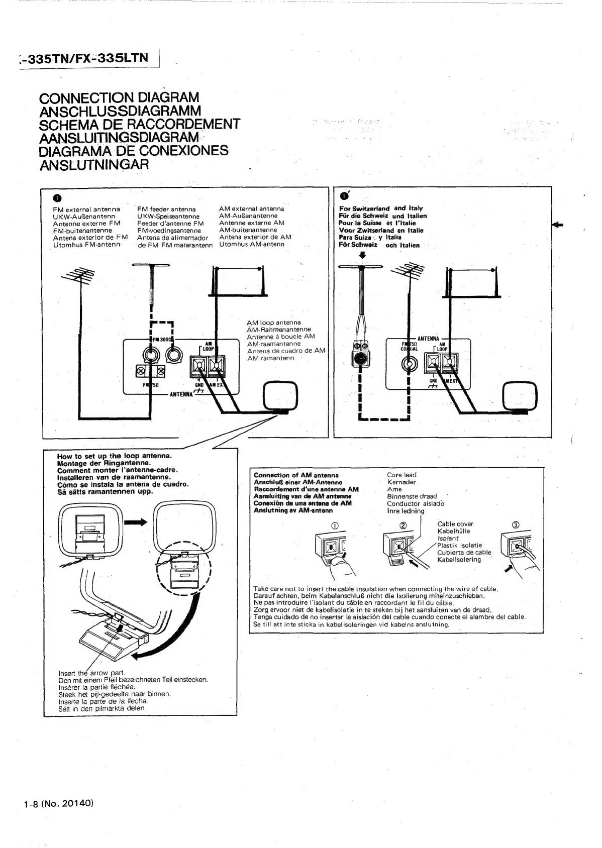
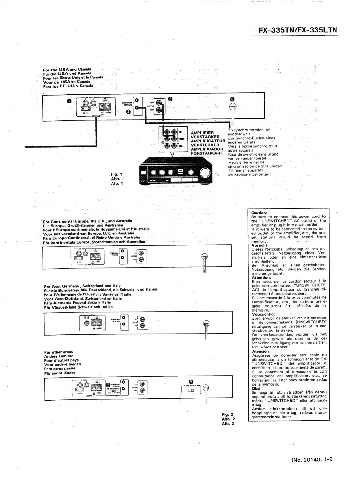
manuals.online logo
Brands
  1. Home
  2. •
  3. Brands
  4. •
  5. JVC
  6. •
  7. Car Receiver
  8. •
  9. JVC FX-335TN User manual

JVC FX-335TN User manual

This manual suits for next models

1

Other JVC Car Receiver manuals

JVC KD-AR8500 User manual

JVC

JVC KD-AR8500 User manual

JVC EXAD KD-LHX502 User manual

JVC

JVC EXAD KD-LHX502 User manual

JVC KD-HDR1 Guide

JVC

JVC KD-HDR1 Guide

JVC EXAD KD-AVX44 User manual

JVC

JVC EXAD KD-AVX44 User manual

JVC KD-R992BT User manual

JVC

JVC KD-R992BT User manual

JVC KV-K1016 User manual

JVC

JVC KV-K1016 User manual

JVC KD-AR870 User manual

JVC

JVC KD-AR870 User manual

JVC KD-G343 User manual

JVC

JVC KD-G343 User manual

JVC KD-G415 Building instructions

JVC

JVC KD-G415 Building instructions

JVC KD-AR765S User manual

JVC

JVC KD-AR765S User manual

JVC KW-R600BT User manual

JVC

JVC KW-R600BT User manual

JVC KD-SC601 Building instructions

JVC

JVC KD-SC601 Building instructions

JVC KD-DV5188 User manual

JVC

JVC KD-DV5188 User manual

JVC KD-R306 User manual

JVC

JVC KD-R306 User manual

JVC KW-XR810 User manual

JVC

JVC KW-XR810 User manual

JVC KD-R492M User manual

JVC

JVC KD-R492M User manual

JVC EXAD KD-LHX551 Guide

JVC

JVC EXAD KD-LHX551 Guide

JVC KD-AR470 - Radio / CD Guide

JVC

JVC KD-AR470 - Radio / CD Guide

JVC KS-FX921 User manual

JVC

JVC KS-FX921 User manual

JVC KD-G744 User manual

JVC

JVC KD-G744 User manual

JVC KD-G333 User manual

JVC

JVC KD-G333 User manual

JVC KD-R601 User manual

JVC

JVC KD-R601 User manual

JVC KD-G521 User manual

JVC

JVC KD-G521 User manual

JVC KD-R921BTEY User manual

JVC

JVC KD-R921BTEY User manual

Popular Car Receiver manuals by other brands

Linear Series LS5050 Operation and installation manual

Linear Series

Linear Series LS5050 Operation and installation manual

Kenwood KRC-160 instruction manual

Kenwood

Kenwood KRC-160 instruction manual

Sony XR-CA430X Service manual

Sony

Sony XR-CA430X Service manual

T+A Elektroakustik K1 CD-RECEIVER operating instructions

T+A Elektroakustik

T+A Elektroakustik K1 CD-RECEIVER operating instructions

SoundMax SM-CDM1052 instruction manual

SoundMax

SoundMax SM-CDM1052 instruction manual

Xtrons HD107HD user manual

Xtrons

Xtrons HD107HD user manual

Mopar RB3 manual

Mopar

Mopar RB3 manual

Clarion ADDZEST DMZ615 owner's manual

Clarion

Clarion ADDZEST DMZ615 owner's manual

Sony XAV-601BT Specifications

Sony

Sony XAV-601BT Specifications

PIE GM12-POD/S Operation manual

PIE

PIE GM12-POD/S Operation manual

Hyundai H-910H instruction manual

Hyundai

Hyundai H-910H instruction manual

Sony XR-C6100 Service manual

Sony

Sony XR-C6100 Service manual

Sony CDX-L600X - Fm/am Compact Disc Player Installation/connections

Sony

Sony CDX-L600X - Fm/am Compact Disc Player Installation/connections

Motorola VWA63 Service manual

Motorola

Motorola VWA63 Service manual

Sound Storm STM93R user manual

Sound Storm

Sound Storm STM93R user manual

Nextar D3201 instruction manual

Nextar

Nextar D3201 instruction manual

Alpine CDE-163BT owner's manual

Alpine

Alpine CDE-163BT owner's manual

Kenwood KDC-X303 quick start guide

Kenwood

Kenwood KDC-X303 quick start guide

manuals.online logo
manuals.online logoBrands
  • About & Mission
  • Contact us
  • Privacy Policy
  • Terms and Conditions

Copyright 2025 Manuals.Online. All Rights Reserved.

FX-335TN/FX-335LT
FX-335LTN/FX-335TN
Contents
Page
Safety
PrecautiONS
«cee
ce
ete
eee
ee
cee
ene
ene
ee
eee
ne
enn
eee
e
es
ee
seer
eee nes
1-2,
Instruction
Book
......--->
Li
Naess
PMS
RPE
ONG
RS
AN
id
Doe
eae
Serhan
See
Re
are
ee
vee
1-3
4:
BiGek
DIAGEAN
ha:
6
08s
we
oak
ees
bn
aoe
renee
tnd
eta
auars
Shaan
Qekine
la
sho
ai
aire
alae,
eee
ee
1-32
2.
Exploded
View
and.
Removal
Procedures...
.----0
sss
ee
eer
rer
ee
sree
sets
ere
e
tet
eess
See
ence
aloreets
1-33
3.
FM/MW/LW
Tuner
Alignment
Procedures
...---
+0
-
eer
e
rete
e
etter
e
errr
t
seen
ees
1-34
4.
Connection
Diagram...
-.
6-0.
ese
eee
eet
eee
tee
Pee
iets
as
Seah
1-35
5.
Internal
Wiring
of
LCD
..
1...
ee
ee
eee
tees
da
Fede
e
eee
eed
eee
nes
Sh
apt
te
eS
naa
ocahteee
ae
gal
a
1-35
6.
Internal
Block
Diagrams
of
Major
ICs
..-.-
2-0-0
eee
eter
eeereeeteee
tenet
teen
eee
eres
1-36
7.
Schematic
Diagram
of
Front-end
Pack....------+-+-ss-0
0:
Ee
Pk
hits
diate
B
Ban,
gheaiiar
ge
desu
sanaoteiay
again
winnie
6
1-39
Schematic
Diagrams
,
FX-335TN/FX-335LTN
Tuner
Section...
60.
-
ee
ee
crete
eee
erent
teers
serene
estes
Insertion
Power
Supply
Section
BEE
Ded
ems
se
fhk
Rtg
te
seo
ch
ce
Ut
ala
lg
bated
magne
sehep
ahs
mete
a
Lie
oh
pn
teats
cies
Insertion
Pelwtad
Geauit
Raard
Ace’
22
2
es
ea
ae
ee
a
a
eee
ee
ee
ot
ee
-
Insertion
No.
20140
Dec.
1989
(-335TN/FX-335LTN
|
Safety
Precautions
1
Warning
aA
RWND
A
_
The
design
of
this
product
contains
special
hardware
and
many
circuits
and
components
specially
for
safety
purposes.
For
continued
protection,
no
changes
should
be
made
to
the
original
design
unless
authorized
in
writing
by
the
manufacturer.
Replacement
parts
must
be
identical
to
those
used
in
the
original
circuits.
Service
should
be
per-
formed
by
qualified
personnel
only.
:
.
Alterations
of
the
design
or
circuitry
of
the
product
should
not
be
made.
Any
design
alterations
of
the
product
should
not
be
made.
Any
design
alterations
or
additions
will
void
the
manufacturer's.
warranty
and.
will
further
relieve
the
manufacturer
of
responsibility
for
personal
injury
or
property
damage
resulting
therefrom.
.
Many
electrical
and
mechanical
parts
in
the
product
have
special!
safety-related
characteristics.
These
characteristics
are
often
not
evident
from
visual
inspection
nor
can
the
protection
afforded
by
them
necessarily
be
obtained
by
using
replacement
components
rated
for
higher
voltage,
wattage,
etc.
Replacement
parts
which
have
these
special
safety
characteristics
are
identified
in
the
Parts
List
of
Service
Manual.
Electrical
components
having
such
features
are
identified
by
shading
on
the
schematics
and
by
(
A\)
on
the
Parts
List
in
the
Service
Manual.
The
use
of
a
sub-
stitute
replacement
which
does
not
have
the
same
safety
characteristics
as
the
recommended
replacement
part
shown
in
the
Parts
List
of
Service
Manual
may
create
shock,
fire,
or
other
hazards.
_
The
leads
in
the
products
are
routed
and
dressed
with
ties,
clamps,
tubings,
barriers
and
the
like
to
be
separated
from
live
parts,
high
temperature
parts,
moving
parts
and/or
sharp
edges
for
the
prevention
of
electric
shock
and
fire
hazard.
When
service
is
required,
the
original
lead
routing
and
dress
should
be
observed,
and
it
should
be
confirmed
that
aey
have
been
returned
to
normal,
after
re-assembling.
.
Leakage
current
check
(Electrical
shock
hazard
testing)
After
re-assembling.
the
product,
always
perform
an
isolation
check
on
the
exposed
metal
parts
of
the
product
(antenna
terminals,
knobs,
metal
cabinet,
screw
heads,
headphone
jack,
control
shafts,
etc.)
to
be
sure
the
product
is
safe
to
operate
without
danger
of
electrical
shock.
Do
not
use
a
line
isolation
transformer
during
this
check.
e
Plug
the
AC
line
cord
directly
into
the
AC
outlet.
Using
a
“Leakage
Current
Tester’’,
measure
the
leakage
current
from
each
exposed
metal
part
of
the
cabinet,
particularly
any
exposed
metal
part
having
a
return
path
to
the
chassis,
to
a
known
good
earth
ground.
Any
leakage
current
must
not
exceed
0.5
mA
AC
(r.m.s.).
e
Alternate
check
method
Plug
the
AC
line
cord
directly
into
the
AC
outlet.
Use
an
AC
voltmeter
having
1,000
ohms
per
volt
or
more
sensi-
tivity
in
the
following
manner.
Connect
a
1,500
22
10
W
resistor
paralleled
by
a
0.15
uF
AC-type
capacitor
be-
tween
an
exposed
meta!
part
and
a
known
good
earth
ground.
Measure
the
AC
voltage
across
the
resistor
with
the
AC
VOLTMETER
AC
voltmeter.
as
(Having
1000
ohms/volt,
.
f
or
more
sensitivity.)
Move
the
resistor
connection
to
each
exposed
metal
part,
particularly
any
exposed
metal
part
having
a
return
path
to
the
chassis,
and
measure
the
AC
volt-
age
across
the
resistor.
Now,
reverse
the
plug
in
the
AC
outlet
and
repeat
each
measurement.
Any
voltage
measured
must
not
exceed
0.75
VAC
(r.m.s.).
This
corresponds
to
0.5
mA
AC
(r.m.s.).
0.15
wF
AC
TYPE
Place
this
probe
on
each
exposed
15002
10W
metal
part.
Good
earth
ground
.
This
equipment
has
been
designed
and
manufactured
to
meet
international
safety
standards.
.
It
is
the
legal
responsibility
of
the
repairer
to
ensure
that
these
safety
standards
are
maintained.
.
Repairs
must
be
made
in
accordance
with
the
relevant
safety
standards.
.
It
is
essential
that
safety
critical
components
are
replaced
by
approved
parts.
.
If
mains
voltage
selector
is
provided,
check
setting
for
local
voltage.
1-2
(No.
20140)
FX-335TN/FX-335LTN
POWER
SPECIFICATIONS
2
Areas
Line
Voltage
&
Frequency:
|
Power
Consumption
USA
i
a
e
|
~~
AC
120
V~,
60
Hz
Canada.
_4
:
U.K.
AC
240
V~,
50
Hz
12
Watts
-
Australia
_
Continental
Europe
AC
220
V~,
50
Hz
:
:
|
:
Other
Areas
AC
115
—
127/220
—
240
VV
selectablé
50/60
Hz
pe
ee
15
Watts
SPANNU
NGSVERSORGUNG
UND
LEISTUNGSAUFNAHME
Lander
|
Netzspannung
und
Frequenz
:
7
Leistungsaufnahme
USA
120
V~.
60
Hz
Kanada
=
‘
=
z
airs
|
.
Gro&britannien
|
240
v~.
50
Hz
12
Watt
Australien
.
;
|
al
Kontinental-Europa
220V~50Hz
:
4
Andere
Gebiete
_
umschaltbar,
115
—
127/220
—
240
V~
50
Hz/60
Hz
-
"15
Watt
“CARACTERISTIQUES.
D'ALIMENTATION
Pays
L
Tension
d’alimentation
et
fréquence.
al
Consommation
.
Eten.
CA
120
V~,
60
Hz
Canada
|
Royaume-Uni
CA
240
Vv,
50
Hz
12
Watts
Australie
Europe
Continentale
CA
220
V~,
50
Hz
CA
115
—
127/220
—
240
V~
commutable,
50/60
Hz
15
Watts
SPANNINGSVEREISTEN
;
Gebieden
Netspanning
en
Frekwentie
;
Stroomverbruik
V.S.
.--
Net
120
V~,
60
Hz
Canada
Engeland
Australié
Vasteland
van
Europa
Overige
landen
ESPECIFICACIONES
DE
ALIMENTACION
Net
240
V~,
50
Hz
12
Watt
Net
220
V~v,
50
Hz
Net
115
—
127/220
—
240
V~
instelbaar,
50/60
Hz
15
Watt
Paises
Voltaje
y
frecuencia
Consumo
1.
—
EEUU.
|
AC
120
V~,60
Hz
Canada
|
rc
7
i
jesBeing
Unido
—}
AC
240
V~v,50
Hz
12
vatios
Australia
|
\~
Europa
Continental
AC
220
V~,
50
Hz
:
Otros
paises
L
AC
115
—
127/220
—
240
V~
seleccionable,
50/60
Hz
tf
15
vatios
me
UPPGIFTER
OM
STROMFORSORJNING
a
Omraden
Natspanning
&
frekvens
L
Effektférbrukning
at
cla
~\
120
V, 60
Hz
7
Kanada
|
Storbritannien
~
240
V,
50
Hz
12
Watt
Australien
-
_
Kontinentala
Europa
~
220
V,50
Hz
[i
Ovriga
lander
~,
115
~
127/220
~
240
V
{omkopplingsbart),
50/60Hz
ote
15
Watt
=
(No.
20140)
1-3
(-335TN/FX-335LTN
|
SPECIFICATIONS
TECHNISCHE
DATEN
UKW-TUNER
Einstellbereich
Nutzbare
Empfindlichkeit
26
dB
Empfindlichkeitsschwelle
iHF
DIN
:
87,5
~
108,0
MHz
:
10,8
dBf
(0,95
zV/
75
Ohm)
CARACTERISTIQUES
TECHNIQUES
SYNTONISEUR
FM
Mono
1,0uV/
75
Ohm
50
dB
Empfindlichkeitsschwelle
Mono
:
16,3
dBf
(1,8
uV/
75
Ohm)
Stereo
:
38,3
dBf
(22,5
uV/
75
Ohm)
Stereoempfindlichkeit
fiir
Signal/Rauschab-
stand
46
dB
FM
TUNER
.
é
IHF
DIN
Tuning
Range
avo
108.0
MHz
Usable
Sensitivity
:
10.8
dBf
(0.95
nV/
75
ohms)
26
dB
Quieting
Sensitivity
Mono
:
1,0
uV/
75
ohms
50
dB
Quieting
Sensitivity
Mono
:
16.3.dBf
(1.8
pV/
75
ohms)
Stereo
:
38.3
dBf
(22.5
uV/
75
ohms)
S/N
46
dB
Stereo
Sensitivity
Stereo
3
23
pV/
75
ohms
Signal
to
Noise
Ratio
Mono
:
80
dB
72
dB
Stereo
:73d8
64
dB
()HF-A)
(weighted)
Total
Harmonic
Distortion
(1
kHz)
Mono
:
0.15
%
0.1%
Stereo
:0.2%
0.3
%
Capture
Ratio
:1.5dB
Selectivity
:
60
dB
55
dB
+400
kHz
+300
kHz
Stereo
Separation
:
(1
kHz)
:
40 dB
40
dB
Frequency
Response
:
30
Hz
~
18
kHz
IF
Response
Ratio
AM
Suppression
Output
Level/
Impedance
Sub-carrier
Sup-
pression
"4-4
(No.
20140)
:
600
mV
+0.3
dB,
-5.0
dB
:
85 dB
at
98
MHz
:
60
dB
600
mV
2.2kohms
2.2
kohms
:
60
dB
Stereo
23
uV/
75
Ohm
Signal/Rauschabstand
Mono
:
80dB
72
dB
Stereo
:73dB
64
dB
(IHF-A)
(bewertet)
Gesamtklirrfaktor
(1
kHz)
Mono
:
0,15
%
0,1
%
Stereo
20.2%
0,3
%
Einfangverhaltnis
:
1,5dB
Selektivitat
:
60 dB
55
dB
:
+400
kHz
=
#300
KHz
Stereokanal-Tren-
nung
{1
kHz)
:
40
dB
40
dB
Frequenzgang
:
30
Hz
~15.
kHz
ZF-Dampfung
AM
Unterdriickung
Ausgangspegel/
tmpedanz
Hilfstrager-Unter-
driickung
:
600
mV
+0,3
dB,
-5,0
dB
:
85
dB
bei
98
MHz
:
60
dB
600
mV
2,2kOhm
2,2
kOhm
:
60
dB
IHF
DIN
Gamme
d‘accord
:
87,5~
:
108,0
MHz
Sensibilité
utilisable
:
10,8
dBf
(0,95
uV/
75
ohms)
Seuilde
sensibilité
26
dB
Mono
:
1.0
uVv/
75
ohms
Seuil
de
sensibilité
50
dB
Mono
:
16,3
dBf
(1,8
ynV/
75
ohms}
Stéréo
:
38,3
dBf
(22,5
uV/
75
ohms)
Sensibilité
stéréo
S/B
46
dB
Stéréo
‘
23
wV/
75
ohms
Rapport
signal/bruit
Mono
:
80
dB
72dB
Stéréo
:
73
dB
64
dB
(IHF-A)
(pondéré)
Distorsion
harmonique
totale
(1
kHz)
Mono
:0,15%
0,1
%
Stéréo
70,2
%
03%
Rapport
de
capture
:
1,5
dB
Sélectivité
:
60
dB
55
dB
+400
kHz
+300
kHz
Séparation
stéréo
(1
kHz)
:
40
dB
40
dB
Réponse
en
fréquence
_
80
Hz
~
15
kHz
+0,3
dB,
-5,0
dB
Rapport
de.réponse
FI
:85dBa
98
MHz
Suppresion
AM
:
60
dB
Niveau/impédance
.
de
sortie
:
600
mV
600
mV.
2,2kohms
2,2
kohms
Suppression
de
sous-porteuse
:
60dB
TECHNISHE
GEGEVENS
FM
TUNER
ae.
a,
IHF
DIN
Afstembereik.
:
87,5~
:
108,0
MHz
Bruikbare
gevoelig-
oo
heid
:
10,8
dBf
(0,95.
4V/
75
ohms)
26
dB
Cemnp
NG
INOR
TENE
Mono
1,0
pV/
75
ohms
50
dB
dempingsgevoeligheid
Mono
:
16,3-dBf
(1,8
2V/
75
ohms)
Stereo
:
38,3
dBf
(22,5
pV/
75
ohms)
46
dB
signaal/ruisverhouding
stereogevoeligheid
Stereo
-
:
23
wV/
75
ohms
Signal-tot-ruis
verhouding
;
Mono
:
80dB
72
dB
Stereo
">
73.dB
64
dB
(IHF-A)
{gewogen)
Totale
harmonische
vervorming
(1
kHz)
Mono
7
0,15
%
0,1
%
Stereo
>
0,2
%
0,3
%
Vangverhouding
:
1,5
dB
Selectiviteit
:
60
dB
55
dB
.
+400
kHz
+300
kHz
Stereo-scheiding
(1
kHz)
+40
dB
—
4008
°
Frekwentiebereik
|
:
30
Hz
~
15
kHz
+0,3
dB,
-5,0dB
Weerspiegeling
mid-—
;
denfrekwenties
:
85
dB
bij
98
MHz
AM-onderdrukking
:
60dB
Uitgangsniveau/
—
impedantie
:
600
mV
600
mV
2,2kohms
2,2
kohms
Onderdrukking
van
draaggolven
:
60
dB
ESPECIFICACIONES
SINTONIZADOR
FM
35
.
JHF
“DIN
Gama
de
sintonia....:.87,5
~
ae
108,0
MHz
Sensibilidad
de
7
:
uso
:
10,8
dBf
(0,95
uV/
75
ohmios)
Sensibilidad
de
silenciamiento
de
26
dB
Mono
s
1,0
nV/
:
75
ohmios
Sensibilidad
de
silenciamiento
de
50
dB
Mono
:
16,3
dBf
:
(1,8
nV/
75
ohmios)
Estéreo
:
38,3
dBf
(22,5
wV/
75
ohmios)
Sensibilidad
estereofénica
con
relacién
de
S/R
de
46
dB
Estéreo
23
uV/
75
ohmios
Relacion
sefial
ruido
fm
Mono
:
80dB
72
dB
Estéreo
:.73
dB
64
dB
(IHF
-A)
(ponde-
rado)
Distorsion
armoénica
total
(1
kHz)
Mono
[015%
.
0,1
%
Estéreo
102%
0.3
.%
Relacién
de
capta-
cién
:
1,5
dB
Selectividad
:
60d8
55
dB
+400
kHz
=
+300
kHz
Separacién
estéreo
(1
kHz)
:
40
dB 40
dB
Respuesta
de
frecuencia
30
Hz
~
15
kHz
+0,3
dB,
-5,0
dB
Relacién
de
respues-
tade
F)
>
85dBa
98
MHz
Supresi6n
de
AM:
60
dB
Nivel
de
salida/
impedancia
:
600
mV
600
mV
2,2
kohmios
2,2
kohmios
Supresién
de
sub-
portadora
:
60
dB
|
FX-335TN/FX-335LTN
TEKNISKA
DATA
FM-TUNER
wa
jHF
*
DIN®
Bandomrade
:
87,5
~
108,0
MHz
Anvandbar
.
kanslighet
:
10,8
dBf
(0,95
nV/
75
ohm)
26
dB
eli
ake
Mono
1,0
pV/
750hm
50
dB
dampningskanslighet
Mono
:
16,3
dBf
(1:8
wV/
75
ohm)
Stereo
:
38,3
dBf
(22,5
wV/
75
ohm)
S/B
46
dB
stereokénslighet
Stereo:
:
23
wV/
75
ohm
Signal/brusférh&llande
Mono
:
80
dB
72
dB
Stereo
:
73
dB
64
dB
(IHF-A)
(vagt)
Total
harmonisk
distorsion
(1
kHz}
Mono
-:
0,15%
0,1%
Stereo
‘0.2%
0,3
%-
Infngningsindex
:
1,5
dB
:
Selektivitet
:60.0B
55
dB
+400
kHz
+300
kHz
Stereoseparation
it
(1
kHz)
:
400B
40.dB
Frekvensomfang
=:
30
Hz
~
15
kHz,
+0,3
dB,
-5,0d8
IF
undertryckning
:
85
dB
vid
98
MHz
AM
undertryckning
:
60
dB
Utgangsniva/
:
600
mV
600
mV
-impedans
2,2
kohm
2,2
kohm
Undertryckning
av
.
underbarvag
:
60
dB
(No..20140)
1-5
(-335TN/FX-335LTN
AM
TUNER
MW
SECTION
Tuning
Range
AM
TUNER
MW
TEIL
Einstellbereich
SYNTONISEUR
AM
SECTION
PO
Gamme
d’accord
Channel
Space
.,
Kanalabstand
Espacement
de
canal
Area
i
Lander
-
Pays
9
kHz
10
kHz
9kHz
10
kHz
-
9
kHz
10
kHz
Europe
|
622
kHz
Europa
522
kHz
Europe
522
kHz
UK.
~
1629
kHz
|GroBoritennien
~
1629
kHz
Royaume-Uni
~
1629
kHz
7
a
522
kHz
~
|
or
522kHz
|
es
522
KHz
pea
~
1629
kHz
~
1629
kHz
aa
~
1629
kHz
z
;
622
kHz
Pore
522
kHz
ateas
522
kHz
|
a
i
—
ee;
Australia
~
1629
kHz
|
~
1629
kHz
ustratie
~
1629
KHz
:
d
Other
531
kHz
530
k
Hz
Andere
531
kHz
530
kHz
Autres
531
kHz
530
k
Hz
area
|
~
1602
kHz
|
~
1600
kHz
Gebiete
~
1602
kHz
|
~
1600
kHz
pays
~
1602
kHz
|
~
1600
kHz
Sensitivity
+
300
nV/m
Empfindlichkeit
:
300
nV/m
Sensibilité
:
300
nV/m
at
999
kHz
or
1000
kHz
bei
999
kHz
oder
1000
kHz
@999
kHz
ou
1000
kHz
30
pV
30
nV
30
nV
at
999
kHz
or
1000
kHz
Signal
to
Noise
Ratio
:
50
dB
(100
mV/m)
at
999
kHz
or
1000
kHz
Selectivity
:
38
4B,
35
dB,
+10
kHzat
+9kHzat
1000
kHz
999
kHz
tmage
Response
Ratio
:
40
dBat
at
999
kHz
or
1000
kHz
1F
Response
Ratio
:
60
dB
LW
SECTION
(FX-331LBK/FX-335LTN
only)
Tuning
Range
Channel
Space
Area
:
1
kHz
Europe
144
kHz
ULK.
353
KH2
i
144
kHz
aid
~
290
kHz
Australia
.
=
Other
area
Sensitivity
600
nV/m
at
245
kHz
100
nV
at
245
kHz
Signal
to
Noise
50 dB
Ratio
at
245
kHz
(100
mV/m)
Selectivity
40
dB
+9
kHz
at
245
kHz
GENERAL
Dimensions
:
435
x
61
x
233.5
mm
(Wx
H
x
D)
(17-3/16"
x
2-7/16"
x
9-3/16"')
Weight
:
2.1
kg
(4.63
Ibs)
Design
and
specifications
subject
to
change
without
notice.
1-6
(No,
20140)
bei
999
kHz
oder
1000
kHz
Signal/Rauschab-
stand
(100
mV/m)
:
50
dB
bei
999
kHz
oder
10000
kHz
Selektivitat
:
38
dB,
35
dB,
+10
kHz
bei
+9
kHz
bei
1000
kHz
=
999
kHz
Spiegel
frequenz-
dampfung
:
40
dB
bei
bei
999
kHz
oder
1000
kHz
ZF-Dampfung
:
60
dB
LW
TEIL
{nur
FX-331LBK/FX-335LTN)
Einstellbereich
Kanalabstand
Europa
Gro&britannien
144
kHz
~
290
kHz
Italien
Australien
Andere
Gebiete
Empfindlichkeit
:
600
nV/m
bei
245
kHz
100
nV
bei
245
kHz
Signal/Rauschab-
:
50
dB
stand
bei
245
kHz
(100
mV/m)
Selektivitat
:
40
dB
+9
kHz
bei
245
kHz
ALLGEMEIN
Abmessungen
:
435
x
61
x
233,5
mm
(BxHxT)
Gewicht
22.1
kg
Technische
Anderungen
vorbehalten.
4999
kHz
ou
1000
kHz
Rapport
signal/bruit
(100
mV/m)
Sélectivité
Rapport
de
sélec-
tivité
Rapport
de
réponse
Fl
SECTION
GO
:50dBa
4999
kHz
ou
1000
kHz
:
38dB,
35
dB,
410kHza
+49kHz4
1000
kHz
999
kHz
:
40dBa
4999
kHz
ou
1000
kHz
:
60
dB
(FX-331LBK/FX-335LTN
seulemehe)
Gamme
d‘accord
Pays
.
1
kHz
Europe
.
144
kHz
Royaume-Uni
~
353
kHz
;
144
kHz
Italie
~
290
kHz
Australie
=
Autres
pays
aj
Sensibilité
:
600
nV/m
&
245
kHz
100
nV
a
245
kHz
Rapport
signal/bruit
:
50
dB
{100
mV/m)}
a
245
kHz
Sélectivité
>
40dB
+9
kHz
a
245
kHz
GENERALES
Dimensions
{Lx
Hx
P)
:
435
x
61
x
233,5mm
Poids
>
2.1
kg
Présentation
et
caractéristiques
modifiables
sans
préavis.
FX-335TN/FX-335LTN
.
AM-TUNER
AM
TUNER
SINTONIZADOR
AM
MG
GEDEELTE
SECCION
OM
‘MV-DEL
ie
OS
Afstembereik
Gama
de
sintonia
Bandomréde-
Bete
Bit
SP
Sn
fy
{"
Kanaalbreedte
[
:
Espaciamiento
de
canales
|
Bee
ee
Ps
“-Kanalavetand
*
me
:
Gebieden
Paises
Land
:
QkHz
10
kHz
9
kHz
10
kHz
LL
[
~OkKHZ
|
10
KHz:
=
=
—
=
>
Europese
522
kHz
~{
Europa
522
kHz
Europa
522
kHz
i
Groot-Britannié|
~
1629
kHz
R.U.
~
1629
kHz
Storbritannien
|
~
1629
kHz
522
kHz
et
522
kHz
“I
522
kHz
Italié
-
Italia
%
:
-
italien
-
~
1629
kHz
a}
L
~
1629
kHz
~
1629
kHz
i
=
522
kHz
Nicaea
B22kHz
)..
aoa
7
‘B22
kHz:
“|
-
strala
=
alien
~
Busia
~
1629
kHz
:
~1629kHz
|
|
~
1629
kHz
_
-
—
Feeadere
531
kHz
530
kHz
Otros
-
531
kHz
530
kHz
Ovriga
531
kHz
530
kHz
jgevieden
‘~
1602
kHz
|
~
1600
kHz
paises
~
1602
kHz
|
~
1600
kHz
|
lander
~
1602
kHz
|
~
1600
kHz
Gevoeligheid
>
300
uV/m
Sensibilidad
:
300
nV/m
Kanslighet
;
300
nV/m
bij
999
kHz
of
1000
kHz’
:
a999
kHz
o
1000
kHz
vid
30
nV
30
nV
999
kHz
eller
1000
KHz
Bi
2Be
Eero
JOUR
a
999
kHz
o
1000
kHz
30
pV
vid
Signaal-tot-ruis
:
Relacion
sefal-
ae
:
999
kHz
eller
1000
kHz
_
(00
mv/m)
:
50
dB
ruido
Signal/
bij
999
kHz
of
1000
kHz
(100
mV/m)
:
50d8
brusférhallande
Selectiviteit
:
38
dB,
35
dB,
a
999
kHz
0
1000
kHz
(100mV/m)
:
50
dB
vid
+10
kKHzbij
+9
kHz
bij
Selectividad
:
38dB,
35
dB,
999 kHz
eller
1000
kHz
1000
kHz,
999
kHz
+10
kHza
+9kHza
Selektivitet
:
38
dB,
35
dB,
Beeldweerspiege-
1000
kHz
999
kHz
£10:kHz
vid
+9
kHz
vid
ling
:
40
dB
Razon
de
respuesta
4000
kHz
999
kHz
bij
999
kHz
of
1000
kHz
imagen
:
40
dB
Speaslsteralvnlige
Weerspiegeling
mid-
a999
kHz
o
1000
kHz
forh.
:
40
dB
vid
denfrekwenties
:60dB
-"
Relacién
de
respue-
.
999
kHz
eller
1000
kHz
sta
de
Fl
:
60
dB
.
IF
&tergivningsférh..:
60
dB
‘LG
GEDEELTE
SECCION
OL
LV-DEL
.
(LLEEN
BIJ
MODEL
FX-
331LBK/FX-335LTN)
(solamente
FX-331
LB
Set
in
(endast
FX-331LBK/FX-335LTN)
Afstembereik
:
Gama
de
sinton
ia
Bandomrade
Kanaalbreedte
E
jami
z
ote
Gebieden
Palace
spaciamiento
dé
canales
band
Kanalavstand
T
kHz
1
kHz
VkHz
Europese
144
kHz
Europa
144
kHz
Europa
144kHz
.
Groot-Britannié
~
353
kHz
R.U.
~
363
kHz
Storbritannien
~
353
k
Hz
:
144
kHz
144
kH.
italié
Italia
.
Italien
144
kHz
~
290
kHz
~
290
kHz
°
~
290
kHz
Australié
-
Australa
Australien
_
,
bk
:
“
-
—
Andere
<
Otros
Ovriga
|gevieden
paises
=
,
lander
~
Gevoeligheid
:
600
pV/m
Sensibilidad
:
600
nV/m
K&nslighet
600
pV/m
bij
245
kHz
a@
245
KHz
vid
245
kHz
100
nV
100
nV
100
pV/m
bij
245
kHz
:
a
245
kHz
vid
245
kHz
Signaal-tot-ruis
:
60dB
Relacion
sefial
:
50dB
verhouding
bij
245
kHz
ruido
a
245
kHz
Signal/brusférhallande
:
50.dB
vid
-(100
mV/m)
(100
mV/m)
(100
mV/m)
245
kHz
od
,
Selektivitet
40
dB
Selectiviteit
:
40dB
Selectividad
:°40dB
+9
kHz
vid
+9
kHz
+9
kHz
245
kHz
bij
245
kHz
a
245
kHz
OVRIGT
oo
ALGEMEEN
GENERALIDADES
Matt
(Bx
HxD)
|
:
435
x
61
x
233,5
mm
Afmetingen
Dimensiones
Vikt
+
2.1
kg
(Bx
Hx
D)
>
435
x
61
x
233,5.mm
(An
x
Al
x
Pr)
:
435
x
61
x
233,5
mm
Gewicht
:
2.1kg
peso
+
2.1
kg
Ratt
till
2ndringar
férbehalles.
Veranderingen
in
technische
gegévens
en
_ontwerp
onder
voorbehoud.
Disefio
y
especificaciones
modificables
sin
aviso
previo.
(No.
20140)
1-7
-335TN/FX-335LTN
|
CONNECTION
DIAGRAM
ANSCHLUSSDIAGRAMM
SCHEMA
DE
RACCORDEMENT
AANSLUITINGSDIAGRAM
-
DIAGRAMA
DE
CONEXIONES
ANSLUTNINGAR
oO
FM
external
antenna
FM
feeder
antenna
AM
external
antenna
For
Switzertand
and
italy
UKW-Aufenantenn
UKW-Speiseantenne
AM-AuRenantenne
Fir
die
Schweiz
und
Italien
Antenne
externe
FM
Feeder
d'antenne
FM
Antenne
externe
AM
Pour
ta
Suisse
et
I’Italie
FM-buitenantenne
FM-voedingsantenne
AM-buitenantenne
Voor
2witserland
en
Italie
Antena
exteriorde
FM
Antenadealimertador
Antena
exterior
de
AM
Para
Suiza
.
y
Italia
Utomhus
FM-antenn
de
FM
FMmatarantenn
Utomhus
AM-antenn
Fr
Schweiz
och
italien
od
AM
loop
antenna
AM-Rahmenantenne
Antenne
a
boucle
AM
AM-raamantenne
Antena
de
cuadro
de
AM
AM
ramantenn
How
to
set
up
the
foop
antenna.
Montage
der
Ringantenne.
Comment
monter
!’antenne-cadre.
installeren
van
de
raamantenne.
Como
se
instala
fa
antena
de
cuadro.
$a
satts
ramantennen
upp.
Connection
of
AM
antenna
Core
lead
Anschlu8
einer
AM-Antenne
Kernader
Raccordement
d’une
antenne
AM
_
Ame
Aansluiting
van
de
AM
antenne
Binnenste
draad
Conexién
de
una
antena
de
AM
Conductor
aislado
Anslutning
av
AM-antenn
Inre
ledning
Cable
cover.
Kabelhille
tsolant
Plastik
isolatie
Cubierta
de
cable
Kabelisolering
Take
care
not
to
insert
the
cable
insulation
when
connecting
the
wire
of
cable.
Darauf
achten,
beim
Kabelanschlu&
nicht
die
lsolierung
miteinzuschieben.
Ne
pas
introduire
|‘isolant
du
céble
en
raccordant
le
fil
du
cable.
Zorg
ervoor
niet
de
kabelisolatie
in
te
steken
bij
het
aansluiten
van
de
draad.
Tenga
cuidado
de
no
insertar
la
aislaciédn
del
cable
cuando
conecte
el
alambre
del
cable.
Se
till
att
inte
sticka
in
kabelisoléringen
vid
kabelns
anslutning.
Insert
the
arrow
part.
Den
mit
einem
Pfeil
bezeichneten
Teil
einstecken.
.
Insérer
la
partie
flechée.
;
Steek
het
pijl-gedeelte
naar
binnen.
Inserte
la
parte
de
la
flecha.
Satt
in
den
pilmarkta
delen.
1-8
(No.
20140)
FX-335TN/FX-335LTN
For
the
USA
and
Canada
Fir
die
USA
und
Kanada
Pour
fes
Etats-Unis
et le
Canada
Voor
de
USA
en
Canada
Para
ios
EE.UU.
y
Canada
oo;
é6ad
COMPU
LINK-1
‘SYNERRO
To
synchro
terminal
of
AMPLIFIER
another
unit
VERSTARKER
:
:
AMPLIFICATEUR
icant
he
cd
adel
ene
VERSTERKER
Vers
la
borne
synchro.
d’un
Greece
autre
appareil
FORST
RKARE
jaar
de
synchro-aansluiting
van
een
ander
toestel
Hacia
el
terminal
de
;
sincronizacién
de
otra
unidad
Tit
annan
apparats
|
synkroniseringskontakt
Caution:
;
Be
sure
to
connect
this
power
cord
to
the
“UNSWITCHED”
AC
outlet
of
the
amplifier
or
plug
it
into
a
wall
outlet.
if
it
were
to
be
connected
to
the
switch-
ed
outlet
of
the
amplifier,
etc.,
the
pre-
For
Continental
Europe,
the
U.K.,
and
Australia
Fir
Europa,
GroBbritannien
und
Australien
Pour
I’Europe
continentale,
le
Royaume-Uni
et
|’Australie
Voor
het
vasteland
van
Europa,
U.K.
en
Australié
Para
Europa
‘Continental,
el
Reino
Unido
y
Australia
:
:
set
stations
would
be
erased
from
Fér
kontinentala
Europa,
Storbritannien
och
Australien
:
oe
memory.
a
hes
Vorsicht:
Dieses
Netzkabel
unbedingt
an
den
un-
geschalteten
Netzausgang
eines
Ver-
starkers
oder
an
eine
Netzsteckdose
anschlieRen.
:
Bei
Anschlu&
an
einen
geschalteten
Netzausgang
etc.
werden
die
Sender-
speicher
geldscht.
Attention:
Bien
raccorder
ce
cordon
secteur
a
la
prise
non
commutée.
("“UNSWITCHED”’
AC)
de
I'amplificateur
ou
brancher
di-
rectement
4
une:
prise
secteur.
COMPULINK-1
°
un
"
ome
‘OUTPUT
ae
wt
For
West
Germany
,
Switzerland
and
Italy
Fir
die
Bundesrepublik
Deutschland,
die
Schweiz
und
Italien
Pour
I‘Allemagne
de
!‘Ouest,
la
Suissetet
IItalie
Voor
West-Duitsland,
Zwitsertand
en
Italie
S'il
est
raccordé
a
la
prise
commutée
de
Para
Alemania
Federal,Suiza
y
Italia
lamplificateur,
etc.,
les
stations
préré-
For
Vasttyskland,
Schweiz
och
Italien
glées
pourront
étre
effacées
de
la
mémoire.
:
Voorzichtig:
Zorg
ervoor
de
stekker
van
dit
netsnoer
in
de
ongeschakelde
(UNSWITCHED)
netuitgang
van
de
versterker
of
in
een
stopkontakt
te
steken,
De
voorkeuzezenders
worden
uit
het
geheugen
gewist
als
deze
in
de
ge-
schakelde
netuitgang
van
een
versterker,
enz.
wordt
gestoken.
ANTENNA
{
per
ans,
°
ig
‘COMPU
LINK=1
n
wo
AMEX
rh
For
other
areas
Andere
Gebiete
Pour
d’autres
pays
Voor
andere
landen
Para
otros
paises
Fér
andra
lander
a8
san
ee
ee
antenna
ge
Oz
0
6
Atencion:
Asegirese
de
conectar
este
cable
de
alimentacién
a
un
tomacorriente
de
CA
“UNSWITCHED’
del
amplificador
o
enchifelo
en
un
tomacorriente
de
pared.
Si
se
conectara
al
tomacorriente
con
conmutador
del
amplificador,
etc.,
se
borrarian
las
estaciones
presintonizadas
de
ja
memoria,
Obs!
Se
noga
till
att.
ndtsladden
fran.
denna
apparat
ansluts
till
férstarkarens
natuttag
markt
“UNSWITCHED”
eller
ett
vagg-
uttag.
Ansluts
stickkontakten
till
ett
om-
Fig.
2
kopplingsbart
nattuttag,
raderas
inpro-
Abb.
2
grammerade
stationer.
Afb.
2
(No.
20140)
1-9
‘-335TN/FX-335LTN
)
External
ANTENNA
terminals
@
External
ANTENNA
terminals
(for
W.
Germany,
Switzerland
and
italy)
@
AM
CHANNEL
SPACING
switch
{Not
provided
on
tuners
for
the
U.SA.,
Canada,
U.K.,
Australia
and
Continental
Europe.)
@
OUTPUT
terminal
Connect
to
the
amplifier’
sTUNER
terminals.
©
COMPU
LINK-1/SY
NCHRO
terminal
Connect
to
the
other.
unit
synchro
terminal.
Voltage
selector
.
(Not
provided
on
tuners
for
U.S.A.,
Canada,
U.K.,
Australia
and
Continental
Europe.)
When
this
equipment
is
used
in
an
area
where
the
supply
voltage
is
different
from
the
present
voltage,
reset
the
voltage
selector
to
the
correct
position.
@
Power
cord
Notes:
1.
Switch
the
power
off
when
connecting
any
component.
2.
Connect
to
an
amplifier
with
left
and
right
channels
connected
correctly.
Reversed
channels
will
degrade
the
stereo
effect.
3.
Connect
plugs
or
wires
firmly.
Poor
contact
may
result
in
hum.
4.
In
case
of
using
the
external
AM
antenna,
be
sure
to
connect
a
ground
wire
to
the
GND
terminal
to
obtain
AM
signals
with
less
noise.
FRONT
PANEL
@
POWER
(ON/STAND
BY)
Press
this
button
to
turn
the
power
ON.
The
dispaly
section
will
light
when
the
power
is
ON.
Press
again
to
set
to
the
STAND
BY
mode.
4-10
(No.
20140)
@
Buchsen
fiir
AnGenantenne
(ANTENNA)
@
Buchsen
fiir
AuRenantenne
(ANTENNA)
(fiir
die
Bundesrepublik
Deutschland,
die
Schweiz
und
italien}
@
AM-Kanalabstandsschalter
(AM
CHANNEL
SPACING)
(nicht
enthalten
in
Tunern.
fir
die
USA,
Kanada,
Brese
reno
len,
Australien
und
Europa)
©
ouTPUT-Klemme
(Ausgang)
An
die
TUNER-Klemmen:
des
Verstiirkers
:
anschlieRen.
@
COMPU
LINK:
1/Synchronisierungsbuchse
(COMPU
LINK-1/SYNCHRO)
~
Mit
einer
Synchro-Buschse
eines
anderen
Gerats
verbinden.
Spannungswahler:
(Nicht
vorhanden
an
Ge-
raten.
fiir
die
USA,
Kanada,
Grofbritannien,
Australien
und
Kontinéntal-Europa.}
Wenn
die
voreingestellte
Netzspannung
an
diesem..
Gerat
.nicht..mit..der,.tatachlich
vor-
handenen’’.Gbereinstimmt,:
den:
Spannungs-
wahler.
auf
den”
erforderlichen
Wert
ein-
stellen.
a
@
Netzkabel
Hinweise:
:
1.
Beim
Anschlu&
von
Komponenter
den
Netzstrom
abschalten.
2.
Bei
Anschlu&
an
einen
Verstarker
auf
ordnungsgemaRen
Anschlu&
der
linken
und
rechten
Kandle
achten,
Umgekehrte
Kanale
beeintrichtigen
den
Stereo-Effekt.
3.
Stecker
oder
Kabel
korrekt
anbringen.
Schlechter
Kontakt
karin
zu
Brummgerau-
schen
fiihren.
4.
Falls
die
externe
AM-Antenne
verwendet
wird,
ist
unbedingt
ein
Erdungsdraht
an
die
GND-Klemme
anzuschlieBen,
damit
AM-
Signale
weniger
Gerauschen
ausgesetzt
sind.
FRONTPLATTE
@
Netztaste
(POWER
ON/STAND
BY)
Zum
Einschalten
(ON)
der
Betriebsspannung
betatigen.
Die
Displayfeld-Anzeigen
leuchten.
Zur
Umschaltung
auf
Betriebsbereitschaft
(STAND
BY)
nochmais
betatigen.
@
Bornes
d’antenne
externe
(ANTENNA)
@
Bornes
d’antenne
“externe
(ANTENNA)
(pour
|‘Allemagne
de.
‘Quest,
la
Suiss
et
|'Htalie)
‘
@
Commutateur
d’espacement
des
canaux
AM
{AM
.CHANNEL
.
SPACING).
(N‘est
pas
prévu
sur
les.
syntoniseurs
destinés
aux
USA,
au
Canada,
au:
Royaume-Uni,
a
l‘Australie
et
a
l'Europe
Continentale)
©
Borne
de
sortie
(OUTPUT)
A
relier
aux
bornes
de
Vamolificateur
du
syntoniseur.
Borne
de
COMPU
LINK-
1/synchronisation
(COMPU
LINK-1/SYNCHRO)
Relier
a.
la
borne
de
synchronisation
de
‘autre
appareil.
@
Sélecteur
‘de
tension
(Pas
pourvu
sur
les
modéles
a
destination
des
Etats-Unis,
Canada,
Royaume
Uni,
Australie
et
Europe
continentale.)
Quand
cet
appareil
est
utilisé
dans
une
région
ot
la
tension
secteur
est
différente
de
celle
qui
est
préréglée,
replacer
Je
sélecteur
de
tension
sur
la
position
cor-
recte.
@
Cordon
d’alimentation
Remarques:
1.
Couper
l’alimentation
lors
du
raccordement
d’une
autre
unité.
2.
Raccorder
4
un
amplificateur
en
respectant
jes
canaux
de
gauche
et
de
droite.
Si
les
canaux
sont
inversés,
l’effet
stéréo
sera
de
qualité
inférieure.
3.
Brancher
correctement
les
prises
et
les
fils.
Un
mauvais
cantact
peovecuarels
des
bourdonnements.
4.
Lorsque
I’antenne
AM
externe
est
utilisée,
s‘assurer
que
le
fil
de
masse
est
raccordé
a
la
borne
de
terre
pour
obtenir
des
signaux_
AM
avec
moins
de
bruit.
PANNEAU
AVANT
@
Alimentation
(POWER
ON/STAND
BY)
Appuyer
sur
cette
touche
pour
mettre
l'appareil
sous
tension
(ON).
A
ce
moment
!’affichage
s‘allume.
Appuyer
une
nouvelle
fois
sur
cette
touche
pour
mettre
l’appareil
hors
tension
(STAND
BY).