manuals.online logo
Brands
  1. Home
  2. •
  3. Brands
  4. •
  5. JVC
  6. •
  7. Car Receiver
  8. •
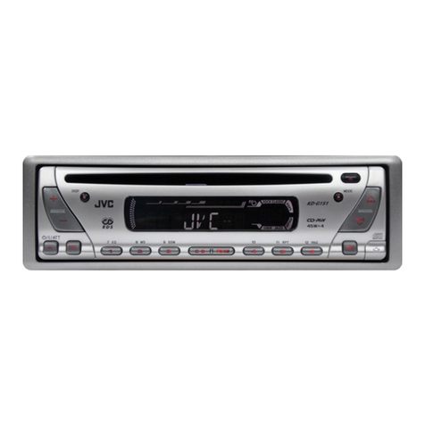
  9. JVC KD-DV5188 User manual

JVC KD-DV5188 User manual

SERVICEMANUAL
COPYRIGHT©2005VictorCompanyof Japan,Limited No.MA173
2005/3
DVD/CD RECEIVER
MA17320053
KD-DV5188
TABLEOFCONTENTS
1PRECAUTIONS. ... .... ... .. .... .. ... ... ... .. . . ... .. ... ... ... .. .... .. ....... ... ... ... .1-3
2SPECIFICSERVICEINSTRUCTIONS.... .. .... ... .. ... ... ... .... ... .... ... .. ... ... .... .. ..1-6
3DISASSEMBLY... ... ... .. ... ... .... .. .... ... ... .. ... ... .... ... ... ... ... . ... ... ... ... .1-7
4ADJUSTMENT. .. ... .... ... ... ... .. .... .. ... ... ... .. ... . . .. ... ... ... .. .. . .. .. .... .. ..1-21
5TROUBLESHOOTING. .... ... .... .. ... ... ... .. ... .... ... ... ... .. .... .. ... ... . . .... .. ..1-29
ß®»¿-«ºº·¨
ËÚóóóóóóóóóóóóóóóóóóóóóóóóóóݸ·²¿
1-2(No.MA173)
SPECIFICATION
Design and specificationsaresubjecttochange withoutnotice.
AUDIOAMPLIFIERSECTION
MaximumPowerOutputFront50Wperchannel
Rear50Wperchannel
ContinuousPowerOutput(RMS)Front19 Wperchannelinto4 ,40 Hzto20 000 Hzatno more
than 0.8%totalharmonicdistortion.
Rear19 Wperchannelinto4 ,40 Hzto20 000 Hzatno more
than 0.8%totalharmonicdistortion.
LoadImpedance4 (4 to8 allowance)
EqualizerControlRangeFrequencies60 Hz,150Hz,400Hz, 1kHz,2.4kHz, 6kHz,15kHz
Level±10 dB
Signal-to-NoiseRatio70 dB
AudioOutputLevelDigital(DIGITALOUT:Optical)Signalwavelength:660 nm
Outputlevel:-21dBmto-15 dBm
Line-OutLevel/Impedance2.5V/20 k load(full scale)
OutputImpedance1k
ColorSystemPAL/NTSC
Video Output(composite)1Vp-p/75
OtherTerminalsLINEIN, CD changer
TUNERSECTION
Frequency RangeFM87.5MHzto108.0MHz
AM531kHzto1602 kHz
FMTunerUsableSensitivity11.3dBf (1.0 kV/75 )
50 dBQuieting Sensitivity16.3dBf(1.8 kV/75 )
AlternateChannelSelectivity(400 kHz)65dB
FrequencyResponse40Hzto15000Hz
StereoSeparation35dB
CaptureRatio1.5dB
AMTunerSensitivity20 kV
Selectivity35dB
DVD/CD PLAYERSECTION
SignalDetection SystemNon-contactopticalpickup (semiconductorlaser)
NumberofChannels2channels(stereo)
Frequency ResponseDVD, fs=48 kHz/96 kHz16 Hzto22 000 Hz
VCD,CD,MP3,WMA16Hzto20 000 Hz
DynamicRange96 dB
Signal-to-NoiseRatio98 dB
Wowand FlutterLessthan measurablelimit
MP3(MPEGAudioLayer3)Max.BitRate:320 kbps
WMA(WindowsMediaAudio)Max.BitRate:192kbps
GENERAL
PowerRequirementOperating VoltageDC 14.4V(11 Vto16 Vallowance)
Grounding SystemNegativeground
AllowableOperating Temperature0pCto+40pC
Dimensions(W IH ID)InstallationSize(approx.)182 mm I52 mm I158 mm
PanelSize(approx.)188 mm I58 mm I11mm
Mass(approx.)1.7kg(excluding accessories)

(No.MA173)1-3
SECTION1
PRECAUTIONS
1.1SafetyPrecautions
ÿÞ«®®- º±®³»¼ ¼«®·²¹ ³±´¼·²¹ ³¿§ ¾»´»º¬±ª»® ±² -±³» °¿®¬-±º¬¸»½¸¿--·-ò̸»®»º±®»ô
°¿§ ¿¬¬»²¬·±² ¬±-«½¸ ¾«®®-·² ¬¸»½¿-»±º°®»º±®³·²¹ ®»°¿·®±º¬¸·--§-¬»³ò
ÿд»¿-» «-» »²±«¹¸ ½¿«¬·±² ²±¬¬±-»» ¬¸»¾»¿³ ¼·®»½¬´§±®¬±«½¸·¬·²½¿-» ±º¿²
¿¼¶«-¬³»²¬±®±°»®¿¬·±² ½¸»½µò
1-4(No.MA173)
1.2Preventing staticelectricity
Electrostaticdischarge(ESD),whichoccurswhen staticelectricitystoredinthe body, fabric, etc. isdischarged, candestroythelaser
diode inthe traverseunit(opticalpickup).Takecaretopreventthiswhen performing repairs.
1.2.1Grounding topreventdamagebystaticelectricity
Staticelectricityinthe workarea can destroythe opticalpickup (laserdiode)indevicessuchasCD players.
Becarefultousepropergrounding inthe area whererepairsarebeing performed.
(1)Groundthe workbench
Ground the workbenchbylayingconductivematerial(suchasaconductivesheet)oran iron plateoveritbeforeplacingthe
traverseunit(opticalpickup)onit.
(2)Groundyourself
Usean anti-staticwriststrap toreleaseanystaticelectricitybuiltup inyourbody.
(3)Handlingthe opticalpickup
Inordertomaintainqualityduring transportandbeforeinstallation,bothsidesof thelaserdiode on the replacement optical
pickup areshorted.Afterreplacement,returnthe shortedpartstotheiroriginalcondition.
(Refertothe text.)
Donotuseatestertochecktheconditionofthelaserdiodeinthe opticalpickup.The tester'sinternalpowersourcecan easily
destroythe laserdiode.
1.3Handling thetraverse unit(opticalpickup)
(1)Beforedisconnecting the flexiblewirefromtheconnector CN101 on the mechanismcontrolboard,soldertheshort-circuitpoints
on the flexiblewire.
Caution:
Ifyou do not followthisinstruction,the DVDpickup maybe damaged.
(2)Disconnectthe flexiblewirefromthe connector CN101 onthe mechanismcontrolboard.
(3)Removethe soldersfromthe short-circuitpointson the flexiblewireafterreplacingthe DVDpickup.
(4)Connecttheflexiblewiretothe connector CN101 on themechanismcontrolboard.
ïÓ
ø½¿°¬·±²÷
ß²¬·ó-¬¿¬·½©®·-¬-¬®¿°
ݱ²¼«½¬·ª»³¿¬»®·¿´
ø½±²¼«½¬·ª»-¸»»¬÷±®·®±² °´¿¬»
Ó»½¸¿²·-³½±²¬®±´¾±¿®¼
ÝÒïðï
Ú´»¨·¾´»©·®»
͸±®¬ó½·®½«·¬ °±·²¬-
(No.MA173)1-5
1.4Importantforlaserproducts
ïòÝÔßÍÍ ïÔßÍÛÎÐÎÑÜËÝÌ
îòÜßÒÙÛÎæ ײª·-·¾´»´¿-»®®¿¼·¿¬·±²©¸»²±°»²¿²¼·²¬»®
´±½µ º¿·´»¼ ±®¼»º»¿¬»¼òߪ±·¼¼·®»½¬»¨°±-«®»¬±¾»¿³ò
íòÝßËÌ×ÑÒæ ̸»®»¿®»²± -»®ª·½»¿¾´»°¿®¬-·²-·¼» ¬¸»
Ô¿-»®Ë²·¬òܱ²±¬¼·-¿--»³¾´»¬¸» Ô¿-»®Ë²·¬òλ°´¿½»
¬¸» ½±³°´»¬»Ô¿-»®Ë²·¬ ·º·¬³¿´º«²½¬·±²-ò
ìòÝßËÌ×ÑÒæ ̸» ÝÜôÓÜ¿²¼ ÜÊܰ´¿§»®«-»-·²ª·-·¾´»
´¿-»®®¿¼·¿¬·±² ¿²¼·-»¯«·°°»¼ ©·¬¸-¿º»¬§-©·¬½¸»-©¸·½¸
°®»ª»²¬ »³·--·±²±º®¿¼·¿¬·±²©¸»²¬¸» ¼®¿©»®·-±°»²¿²¼
¬¸» -¿º»¬§·²¬»®´±½µ-¸¿ª»º¿·´»¼ ±®¿®»¼»º»¿¬»¼ò׬·-
¼¿²¹»®±«-¬±¼»º»¿¬¬¸» -¿º»¬§-©·¬½¸»-ò
ëòÝßËÌ×ÑÒæ ׺-¿º»¬§-©·¬½¸»-³¿´º«²½¬·±²ô¬¸» ´¿-»®·-¿¾´»
¬±º«²½¬·±²ò
êòÝßËÌ×ÑÒæ Ë-»±º½±²¬®±´-ô¿¼¶«-¬³»²¬-±®°»®º±®³¿²½»±º
°®±½»¼«®»-±¬¸»®¬¸¿² ¬¸±-»-°»½·º·»¼¸»®»·²³¿§®»-«´¬·²
¸¿¦¿®¼±«-®¿¼·¿¬·±²»¨°±-«®»ò
ÎÛÐÎÑÜËÝÌ×ÑÒßÒÜ ÐÑÍ×Ì×ÑÒÑÚÔßÞÛÔÍ
д»¿-» «-» »²±«¹¸ ½¿«¬·±² ²±¬¬±
-»» ¬¸»¾»¿³ ¼·®»½¬´§±®¬±«½¸·¬
·²½¿-» ±º¿²¿¼¶«-¬³»²¬±®±°»®¿¬·±²
½¸»½µò
ÉßÎÒ×ÒÙÔßÞÛÔ
ÝßËÌ×ÑÒ æÊ·-·¾´» ¿²¼ ײª·-·¾´»
´¿-»® ®¿¼·¿¬·±² ©¸»² ±°»² ¿²¼
·²¬»®´±½µ º¿·´»¼±®¼»º»¿¬»¼ò
ßÊÑ×ÜÜ×ÎÛÝÌÛÈÐÑÍËÎÛÌÑ
ÞÛßÓò ø»÷
ÊßÎÒ×ÒÙ æÍ§²´·¹ ±½¸
±-§²´·²¹ ´¿-»®-¬®;´²·²¹ ²<®
¼»²*°°²¿-±½¸-°<®®»²<®
«®µ±°°´¿¼ò Þ»¬®¿µ¬¿ »¶
-¬®;´»²òø-÷
ÊßÎÑ æ ߪ¿¬¬¿»--¿ ¶¿ -«±¶¿´«µ·¬«-
±¸·¬»¬¬«²¿¬¿·ª·¿´´·-»²¿ ±´»¬¿´¬¬··²¿
²<µ§ª<´´» ¶¿ ²<µ§³<¬¬*³<´´»
´¿-»®-<¬»·´§´´»òÊ<´¬<-<¬»»²
µ±¸¼·-¬«³·-¬¿ -«±®¿¿²·¬-»»-·ò øº÷
ßÜÊßÎÍÛÔ æÍ§²´·¹ ±¹«-§²´·¹
´¿-»®-¬®;´·²¹²;®³¿-µ·²»²»®
;¾»²»´´»®·²¬»®´±½µ»²º»¶»´»®ò
˲¼¹;¼·®»µ¬»»µ-°±²»®·²¹¬·´
-¬®;´·²¹òø¼÷
ÝÔßÍÍ ï
ÔßÍÛÎÐÎÑÜËÝÌ
1-6(No.MA173)
SECTION2
SPECIFICSERVICEINSTRUCTIONS
Thisservicemanualdoesnot describeSPECIFICSERVICEINSTRUCTIONS.
(No.MA173)1-7
SECTION3
DISASSEMBLY
3.1Mainbodysection
3.1.1Removing thefrontpanelassembly
(SeeFig.1)
Pushthedetachbutton inthe lowerleftpartofthefrontpanelas-
semblyand removethe frontpanelassembly.
Fig.1
3.1.2Removing thebottomcover
(SeeFig.2)
Reference:
Removethe front panelassemblyasrequired.
(1)Releasethe twojoints a,twojoints band joint c.
(2)Removethebottomcoverfromthe mainbody.
Caution:
Donotdamage the mainboardwhen releasing thejointsusing
ascrewdriverorasimilartool.
Fig.2
Ú®±²¬°¿²»´¿--»³¾´§
Ü»¬¿½¸¾«¬¬±²
Þ±¬¬±³½±ª»®
¾
¾
¿
¿
½
1-8(No.MA173)
3.1.3Removing thefrontchassisassembly
(See Figs.3and 4)
Removethefrontpanelassemblyandbottomcover.
(1)Fromthe frontside ofthe mainbody,removethetwo
screws Aattaching the frontchassisassembly.(See
Fig.3.)
(2)Fromthe bothsidesofthe mainbody,removethe two
screws Battaching the frontchassisassembly.(See
Fig.4.)
(3)Releasethetwojoints dand twojoints e.(See Fig.4.)
Fig.3
Fig.4
3.1.4Removing thesideheatsink
(See Fig.5)
Reference:
Removethe frontpaneland frontchassisassembliesasre-
quired.
Fromtheleftsideofthemainbody,removethe twoscrews Cand
threescrews Dattaching the side heat sink.
Fig.5
ß
Ú®±²¬½¸¿--·-¿--»³¾´§
¼
¼
Ú®±²¬½¸¿--·-¿--»³¾´§
Þ
»
»
Þ
Ý
ÜÍ·¼» ¸»¿¬-·²µ
(No.MA173)1-9
3.1.5Removing therearbracket
(SeeFig.6)
Removethe bottomcover.
(1)Fromtheback side ofthe mainbody,removethetwo
screws E, twoscrews E', screw F, twoscrews Gandthree
screws Hattachingthe rearbracket.
(2)Removethe LINEINcablefromthe rearbracketinthedi-
rectionof thearrow.
Reference:
Whenattaching the LINEINcable,insertitinaslotofthe
rearbracketandhang iton awireholder.
Whenattaching the screws E', attachthe cableholderswith
them.
3.1.6Removing themainboard
(See Figs.6and 7)
Removethe front panelassembly, bottomcover, front chassis
assemblyand sideheatsink.
Reference:
Removethe rearbracketasrequired.
(1)Fromthebackside ofthemainbody,removethe three
screws Hattaching the mainboard.(See Fig.6.)
(2)Fromthebottomside ofthemainbody,removethethree
screws Jattachingthe mainboard. (SeeFig.7.)
(3)Disconnectthe connector CN961 on themainboardfrom
the DVDmechanismassemblyand takeoutthemain
boardfromthe mainbody.(See Fig.7.)
Fig.6
Fig.7
3.1.7Removing theDVDmechanismassembly
(SeeFig.8)
Removethe front panelassembly, bottomcover, front chassis
assembly,side heat sinkand mainboard.
(1)Fromtheinside ofthe topchassis,removethethree
screws Kattachingthe DVDmechanismassembly.
(2)Takeoutthe DVDmechanismassemblyfromthe top cha
sis.
Fig.8
λ¿®¾®¿½µ»¬
Ù
Ø
Ûù
Ý¿¾´»¸±´¼»®
Ú
Ø
Ø
Û
Ûù
Ý¿¾´»¸±´¼»®
É·®»¸±´¼»®
Í´±¬
Ô×ÒÛ×Ò½¿¾´»
λ¿®¾®¿½µ»¬
Û
ÝÒçêï
Ö
Ö
Ó¿·²¾±¿®¼
Ö
ÕÕ
Õ
ÜÊܳ»½¸¿²·-³¿--»³¾´§
̱° ½¸¿--·-
1-10 (No.MA173)
3.1.8Removing themainsub board
(See Figs.9to11)
Removethe frontpanelassembly,bottomcover,front chassis
assembly,side heatsink,mainboardand DVDmechanismas-
sembly.
(1)Fromthe top side ofthe DVDmechanismassembly,re-
movethe twoscrews Lattaching thedustcover.(See
Fig.9.)
(2)Removethe dust coverfromtheDVDmechanismassem-
bly.(See Fig.9.)
Reference:
When attaching the dustcover,align thejoints finthe
holesofthe dustcoverbeforeattaching thescrews L.
(See Fig.9.)
(3)Releasethe lock ofthe connector CN962 on themainsub
boardand disconnectthe cardwire.(See Fig.10.)
(4)Bend thejoint ginthe directionof the arrow.(See Fig.10.)
(5)Removethe twoscrews Mattaching themainsubboard
and removethe mainsubboardfromtheDVDmechanism
assembly.(See Fig.10.)
Reference:
Whenattaching themainsubboard,align the joints hinthe
holesofthe mainsub boardbeforeattaching the screws M.
(See Fig.10.)
Whenthe resolution ofDVDmechanismassemblyisdone
sequentially,removethe twoscrews Nattaching thesupport
bracket. (SeeFig.11.)
Removethecardwirefromthe connector CN401 asre-
quired.(See Fig.11.)
Fig.9
Fig.10
Fig.11
Ô
Ô
ÜÊܳ»½¸¿²·-³¿--»³¾´§
Ü«-¬½±ª»® º
º
Ý¿®¼©·®»
¹
Ó
¸
¸
ÝÒçêî
Ô±½µ
Ó¿·²-«¾ ¾±¿®¼
ÜÊܳ»½¸¿²·-³¿--»³¾´§
Ý¿®¼©·®»
Ò
Í«°°±®¬¾®¿½µ»¬ ÝÒìðï
(No.MA173)1-11
3.1.9Removing theswitchboard
(See Figs. 12 to14)
Removethe frontpanelassembly.
(1)Fromthe back side ofthe frontpanelassembly,removethe
fivescrews Pattachingthe rearcover. (SeeFig.12.)
(2)Releasethe ten joints iattaching the rearcovertothefront
panelassembly.(See Fig.13.)
(3)Takeouttheswitchboardwhilelifting the switchboard
fromthefrontpanelassemblylittlebylittle. (SeeFig.14.)
Reference:
Removethe volumeknob fromthe front sideof the frontpanel
assemblyat thesametime.
Note:
Donotlosethe compressionspringswhen removingthe
switchboard.(See Fig.14.) Fig.12
Fig.13
Fig.14
Ð
Ð
λ¿®½±ª»®
Ú®±²¬°¿²»´¿--»³¾´§
Ð
·
·
λ¿®½±ª»®
··
Í©·¬½¸¾±¿®¼ Ú®±²¬°¿²»´¿--»³¾´§
ݱ³°®»--·±² -°®·²¹
ݱ³°®»--·±² -°®·²¹
1-12 (No.MA173)
3.2DVDmechanismassembly
3.2.1Removing themechanismcontrolboard
(See Fig.1)
Caution:
Beforedisconnectingthe flexiblewireextending fromthe DVD
pickup, solderthe short-circuitpointonthe flexiblewireusing
agrounding soldering iron. Ifyou donot followthisinstruction,
the DVDpickup maybe damaged.
(1)Turnoverthe body,and solderthe short-circuitpointson
the flexiblewireextending fromtheDVDpickup.
(2)Disconnect theflexiblewirefromconnector CN101 onthe
mechanismcontrolboard.
(3)Disconnectthecardwirefromconnector CN201 onthe
mechanismcontrolboard.
(4)Disconnect theflexiblewirefromconnector CN202 onthe
mechanismcontrolboard.
(5)Unsoldertwosolderedpoints aonthe mechanismcontrol
boardandremovethewireextending fromthefeedmotor.
(6)Removethescrew Aattachingthe lugwire.
(7)Removethe twoscrews Bandscrew Cattaching the
mechanismcontrolboard.
Caution:
Asthe flexiblewiretobe connectedto CN101, makesureto
attachittothe mechanismcontrolboardusingadouble
tape.
Afterreassembling,unsolderthe short-circuitpoints.
Fig.1
ܱ«¾´»¬¿°»
Ú»»¼³±¬±®
Ó»½¸¿²·-³½±²¬®±´¾±¿®¼
ÝÒîðî
ÝÒïðï
Þ
¿
Ý
Þ
ÝÒîðï
Ú´»¨·¾´»©·®»
͸±®¬ó½·®½«·¬°±·²¬-
ß
Ô«¹ ©·®»
(No.MA173)1-13
3.2.2Removing thetop cover
(SeeFig.2)
(1)Removethe twoscrews Dattaching the topcoveron the
backofthe body.
(2)Removethetop coverupward.
Reference:
When reassembling,setpart bofthe topcoverunderthe
bending part cofthechassisframe.
3.2.3Removing themechanismsection
(SeeFig.2to4)
Removethe top cover.
(1)Fromthe bottomofthe body,removethe screw Eattaching
the lugwire. (SeeFig.2.)
(2)Removethe twoscrews Fattaching the rightand leftstop-
person thefrontside.(See Fig.2.)
(3)Removethe twofloating springson the bottomofthe body.
(See Fig.3.)
(4)Movethemechanismsectionupwardand removefromthe
chassisframe.
The three damperspringscomeofffromthe dampers.
(See Fig.4.)
Caution:
Whenreassembling,reattachthedamperspringtothe
damperrespectivelyand insertthethree shaftsonthe bot-
tomof themechanismtothe dampers.
Beforeinserting theshaft tothe dampers,applyIPA tothe
holeofdamper.
Fig.2
Fig.3
Fig.4
Ü
̱°½±ª»®
ͬ±°°»®
ͬ±°°»®
Ú
Ú
¾
½Û
Ô«¹ ©·®»
Ü
Ú´±¿¬·²¹-°®·²¹
Ó»½¸¿²·-³-»½¬·±²
Ü¿³°»®øÎ÷
øÐ«®°´»÷
Ü¿³°»®øÚ÷
øÞ´¿½µ÷
Ü¿³°»®øÚ÷
øÞ´¿½µ÷
ݸ¿--·-º®¿³»
Ü¿³°»®ÍÐòøÚ÷
øÍ·´ª»®÷
Ü¿³°»®ÍÐòøÚ÷
øÍ·´ª»®÷
Ü¿³°»®ÍÐòøÎ÷
øÎ»¼÷
1-14 (No.MA173)
3.2.4Removing theclamperunit
(See Fig.5to7)
Removethetop coverand the mechanismsection.
(1)Removethe clamper2spring onthebottomofthe mecha-
nismsection.(See Figs.5.and6.)
(2)Releasethe part dofthe clamperspringfromthebending
partofthe chassisbaseassembly.(See Fig.7.)
(3)Movetheclamperunitinthe direction ofthe arrowand turn.
Releasethetwojoints eand f,thenremovethe clamper
unitupward.(SeeFig.6.)
3.2.5Reattaching theclamperunit
(See Fig.5to9)
(1)Attachthe clamperspring tothe clamperunit.(SeeFig.8.)
(2)Movethe clamperunit tosetthe sidejoints eand f toeach
bossofthe chassisbaseassembly. Makesurethat part g
isinserted tothe notchofthe chassisbaseassembly.(See
Figs.5and 9.)
(3)Movethe part doftheclamperspringtothe outsideofthe
bendingpartofthe chassisbaseassembly.(See Fig.7.)
(4)Attachthe clamper2spring tothechassisbaseassembly.
(See Figs.5and6.)
Caution:
When reattaching,temporarilyhookthe end ofthe clamper
spring asshowninthe figuretomakethe workeasy.(See
Fig.8.)
Fig.5
Fig.6
Fig.7
Ý´¿³°»®«²·¬
Ý´¿³°»®-°®·²¹
Ý´¿³°»®î-°®·²¹
¹
º
»
ݸ¿--·-¾¿-»¿--»³¾´§
Ý´¿³°»®î-°®·²¹
ݸ¿--·-¾¿-»¿--»³¾´§
Ý´¿³°»®-°®·²¹
ݸ¿--·-¾¿-»¿--»³¾´§
¼
(No.MA173)1-15
Fig.8
Fig.9
Ý´¿³°»®«²·¬
Ý´¿³°»®-°®·²¹
Ò±¬½¸
¹
Ý´¿³°»®«²·¬
1-16 (No.MA173)
3.2.6Removing thefrontunit
(See Fig.10 to12)
Removethetop coverand the mechanismsection.
(1)Disconnect theflexiblewirefromconnector CN202 onthe
mechanismcontrolboardatthe bottomofthe body.(See
Fig.10.)
(2)Removethe screw Gattaching thefrontunitonthe top of
the body.(SeeFig.11.)
(3)Movethefront unittowardthe fronttoreleasejoint h,and
releasetwojoints iand jon the rightside ofthechassis
baseassembly.Then removethefrontunitupward.(See
Figs.11 and 12.)
(4)Removethe twoscrews Hattaching the switchboard.(See
Fig.12.)
Reference:
You can removethe switchboardonlywithoutremoving the
frontunit.
Caution:
When reassembling,attachthe flexiblewireextending from
the switchboardusing thedoubletape. (See Figs.10and 12.)
Fig.10
Fig.11
Fig.12
Ó»½¸¿²·-³½±²¬®±´¾±¿®¼
Ú´»¨·¾´»©·®»
ÝÒîðî
ܱ«¾´»¬¿°»
Ù
Ú®±²¬«²·¬
¸
¸
Ú®±²¬«²·¬
Í©·¬½¸¾±¿®¼
¶
Ù
Ø
·
ܱ«¾´»¬¿°»
(No.MA173)1-17
3.2.7Removing theloading armassembly
(See Fig.13 ,14)
Removethe topcover,the mechanismsection and the front
unit.
(1)Fromthe top ofthe body,movethe loading armassembly
fromthe frontside upward,and releasethebossesfrom
the rightand leftjoints kand mofthe chassisbaseassem-
bly.
(2)Releasethebossfromnotch noftheconnectarmon the
rightsideofthe body,andreleasetheboss fromnotch pof
the slidecamassemblyon theleftside.
Fig.13
Fig.14
µ²
³
Ô±¿¼·²¹¿®³ ¿--»³¾´§
µ
²
³
Ô±¿¼·²¹¿®³ ¿--»³¾´§
°
Í·¼» ½¿³
¿--»³¾´§
ݱ²²»½¬¿®³
1-18 (No.MA173)
3.2.8Removing therod (L)(R)/rollerassembly
(See Fig.15 and 16)
Removethe topcover,themechanismsection,the frontunit
and the loadingarmassembly.
(1)Releasetherod (L)and(R)fromthe joints qatthe bottom
ofthe loading armassembly(See Fig.15.)
(2)Removethe rollerassemblyfromtheloading arm assem-
bly.(See Fig.16.)
(3)Removethe twocollarsandwasherfromthe rollerassem-
bly.(See Fig.16.)
Caution:
Afterattaching theloading armassemblytotherollerassem-
bly,attachtherod (L)and(R). Attachtherodstothe right and
leftcollarsofthe roller.(See Fig.15.)
When reattaching therod (L)and(R)tothe loading arm as-
sembly,engage eachjointasshowninFig.15.Asjoints qof
the rod (L),let therod through qbeforereattachingit.
Fig.15
Fig.16
¯
¯
¯¯
¯
¯
α¼øÎ÷
Ô±¿¼·²¹¿®³ ¿--»³¾´§
α¼øÔ÷
ݱ´´¿® ݱ´´¿®
α¼øÎ÷ α¼øÔ÷
α´´»®¿--»³¾´§
É¿-¸»®
ݱ´´¿®
ݱ´´¿®
α¼øÔ÷
Ô±¿¼·²¹¿®³ ¿--»³¾´§
α¼øÎ÷
(No.MA173)1-19
3.2.9Removing theDVDpickup assembly
(See Fig.17 to19)
Removethe mechanismcontrolboard.
(1)Fromthe bottomofthe body,turnthefeed gearinthedi-
rectionofthe arrowtomovetheDVDpickup outwards.
(See Fig.17.)
(2)Removethescrew Jattaching the thrustspring.(See
Fig.17.)
(3)RemovetheDVDpickup assemblyupwardon the L.S.gear
sideand releasefromsubshaft atjoint r.Movethe lead
screwofthe DVDpickupassemblyinthe directionofthe
arrowtoreleasefromjoint s.(See Fig.18.)
Caution:
Whenreleasing the lead screwatjoint s,theL.S.collar
comesoffatthe end ofthe lead screw.When reas-
sembling,reattachtheL.S.collartothe lead screwand
engage joint s.(See Fig.18.)
Whenreattachingthe L.S.collar,reattachittothe point
softhe leadscrew,and tothe rod (M). Makesurethat
the L.S.collarisseton the rod (M) spring.(See Fig.18.)
(4)Removethe screw Kattaching the rackspring/rackplate
on the DVDpickup.(See Fig.19.)
(5)Pulloutthe leadscrew.(SeeFig.19.)
Caution:
Performadjustmentafterreplacing thepickup.
Fig.17
Fig.18
Fig.19
Ö
Ú»»¼¹»¿®
̸®«-¬-°®·²¹
ÜÊÜз½µ«° ¿--»³¾´§
®
-
ÔòÍò½±´´¿®
α¼øÓ÷
ÔòÍò¹»¿®
Ô»¿¼-½®»©
Í«¾ -¸¿º¬
ÜÊÜз½µ«° ¿--»³¾´§
Õ
ο½µ-°®·²¹
ο½µ°´¿¬»
ÔòÍò½±´´¿®
ÜÊÜз½µ«°
Ô»¿¼-½®»©
1-20 (No.MA173)
3.2.10Removing thespindlemotor
(See Fig.20)
Removethe mechanismcontrolboard.
Removethe twoscrews Lattaching the spindlemotoronthe
bottomofthe body.
Caution:
Performadjustmentwhen reattachingthe spindlemotor.
Fig.20
3.2.11Removing thefeedmotorassembly
(See Fig.21 and 22)
Removethe mechanismcontrolboard.
(1)RemovethefeedTRI.springon the bottomofthebody.
(See Fig.21.)
(2)Removethe twoscrews Mattachingthefeed motoras-
sembly. (SeeFig.21.)
(3)Removethe slitwasherfromthe motorH.assemblyand
pull outtheworm wheel.(SeeFig.22.)
Removethe twoscrews Nattachingthe feedmotor.(See
Fig.22.)
Fig.21
Fig.22
Ô
Ͱ·²¼´»³±¬±®
Ó
Ú»»¼³±¬±®¿--»³¾´§
Ú»»¼ÌÎ×ò -°®·²¹
Ú»»¼³±¬±
®
Ó±¬±®Øò¿--»³¾´§
ɱ®³ ©¸»»´
Í´·¬©¿-¸»®
Ò

Other JVC Car Receiver manuals

JVC KD-G432 User manual

JVC

JVC KD-G432 User manual

JVC KD-G301 Guide

JVC

JVC KD-G301 Guide

JVC GET0241-001B User manual

JVC

JVC GET0241-001B User manual

JVC KD-R716 User manual

JVC

JVC KD-R716 User manual

JVC EXAD KD-SHX701 User manual

JVC

JVC EXAD KD-SHX701 User manual

JVC KD-AVX22 User manual

JVC

JVC KD-AVX22 User manual

JVC KD-S5055SU User manual

JVC

JVC KD-S5055SU User manual

JVC KD-R492M User manual

JVC

JVC KD-R492M User manual

JVC KD-R756 User manual

JVC

JVC KD-R756 User manual

JVC KD-S48 Guide

JVC

JVC KD-S48 Guide

JVC KD-DB98BT User manual

JVC

JVC KD-DB98BT User manual

JVC KD-G385 User manual

JVC

JVC KD-G385 User manual

JVC KS-FX942R User manual

JVC

JVC KS-FX942R User manual

JVC KD-G734 Guide

JVC

JVC KD-G734 Guide

JVC KW-HDR81BT User manual

JVC

JVC KW-HDR81BT User manual

JVC KW-V66BT User manual

JVC

JVC KW-V66BT User manual

JVC KD-R601 Guide

JVC

JVC KD-R601 Guide

JVC KD-R801 User manual

JVC

JVC KD-R801 User manual

JVC KD-LX330R Manual

JVC

JVC KD-LX330R Manual

JVC KD-SH9101 User manual

JVC

JVC KD-SH9101 User manual

JVC KD-AR5500 User manual

JVC

JVC KD-AR5500 User manual

JVC KDDV5400 - DVD Player With Radio User manual

JVC

JVC KDDV5400 - DVD Player With Radio User manual

JVC KD-AVX2 - DVD Player With LCD Monitor Guide

JVC

JVC KD-AVX2 - DVD Player With LCD Monitor Guide

JVC GET0647-004A Guide

JVC

JVC GET0647-004A Guide

Popular Car Receiver manuals by other brands

MAC Audio SX 12 Owner's manual/warranty document

MAC Audio

MAC Audio SX 12 Owner's manual/warranty document

Jensen VR185 owner's manual

Jensen

Jensen VR185 owner's manual

Dual XDM265 Installation & owner's manual

Dual

Dual XDM265 Installation & owner's manual

Blaupunkt KIEL CD36 operating instructions

Blaupunkt

Blaupunkt KIEL CD36 operating instructions

Kenwood KDC-BT660U instruction manual

Kenwood

Kenwood KDC-BT660U instruction manual

Sony MEX-BT38UW - Bt Slot Usb 1wire Specification sheet

Sony

Sony MEX-BT38UW - Bt Slot Usb 1wire Specification sheet

Pioneer DEH-S2000UI owner's manual

Pioneer

Pioneer DEH-S2000UI owner's manual

Blaupunkt Bologna C51 operating instructions

Blaupunkt

Blaupunkt Bologna C51 operating instructions

Boss Audio Systems 630U user manual

Boss Audio Systems

Boss Audio Systems 630U user manual

Ssl DD888 user manual

Ssl

Ssl DD888 user manual

Pioneer DEH-5250SD installation manual

Pioneer

Pioneer DEH-5250SD installation manual

Sony CDX-S2210 - Fm/am Compact Disc Player operating instructions

Sony

Sony CDX-S2210 - Fm/am Compact Disc Player operating instructions

Philips CEM2200 user manual

Philips

Philips CEM2200 user manual

Boss Audio Systems 630UA user manual

Boss Audio Systems

Boss Audio Systems 630UA user manual

Porsche PCM3 user manual

Porsche

Porsche PCM3 user manual

Pioneer DEH-X6810BT owner's manual

Pioneer

Pioneer DEH-X6810BT owner's manual

Sony XR-1800 Service manual

Sony

Sony XR-1800 Service manual

Sony MDX-100 operating instructions

Sony

Sony MDX-100 operating instructions

manuals.online logo
manuals.online logoBrands
  • About & Mission
  • Contact us
  • Privacy Policy
  • Terms and Conditions

Copyright 2025 Manuals.Online. All Rights Reserved.