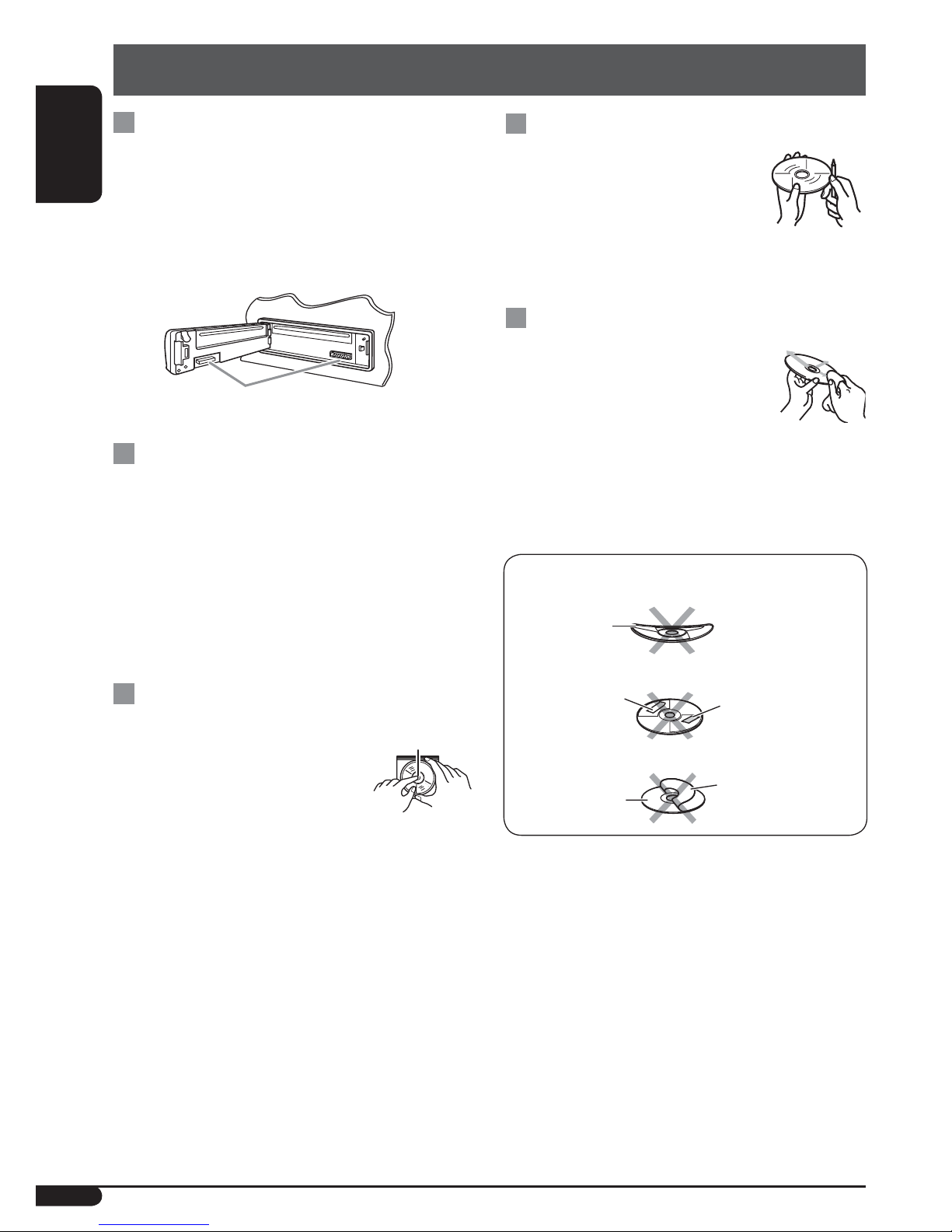
JVC KD-G126 User manual

ENGLISH
For canceling the display demonstration, see page 5.
For installation and connections, refer to the separate manual.
INSTRUCTIONS
GET0331-001A
[U/UH]
KD-G126/KD-G125
5
CD RECEIVER KD-G126/KD-G125
KD-G126
KD-G125
KD-G125
KD-G126
Cover_KD-G126_001A_f.indd 2 10/5/05 2:04:29 PM

ENGLISH
2
How to reset your unit
• Your preset adjustments will also be erased.
• If a disc is loaded, it will eject. Be careful not to
drop the disc.
How to forcibly eject a disc
• If this does not work, reset your unit.
• Be careful not to drop the disc when it ejects.
Thank you for purchasing a JVC product.
Please read all instructions carefully before operation, to ensure your complete understanding and to
obtain the best possible performance from the unit.
IMPORTANT FOR LASER PRODUCTS
1. CLASS 1 LASER PRODUCT
2. CAUTION: Do not open the top cover. There are no user serviceable parts inside the unit; leave
all servicing to qualified service personnel.
3. CAUTION: Visible and invisible laser radiation when open and interlock failed or defeated.
Avoid direct exposure to beam.
4. REPRODUCTION OF LABEL: CAUTION LABEL, PLACED OUTSIDE THE UNIT.
How to use the M MODE button
If you press M MODE, the unit goes into
functions mode, then the number buttons work
as different function buttons.
Ex.: When number button 2 works as
MO (monaural) button.
To use these buttons for their original
functions again after pressing M MODE, wait
for 5 seconds without pressing any of these
buttons until the functions mode is cleared or
press M MODE again.
Time countdown indicator
Warning:
If you need to operate the unit while driving,
be sure to look ahead carefully or you may be
involved in a traffic accident.
Caution on volume setting:
Discs produce very little noise compared
with other sources. Lower the volume
before playing a disc to avoid damaging
the speakers by the sudden increase of the
output level.
EN02-05_KD-G125_126[UN]f.indd 2 10/4/05 11:54:41 AM

ENGLISH
3
CONTENTS
Control panel — KD-G126 and KD-G125 ........ 4
Getting started................................. 5
Basic operations.................................................... 5
Radio operations .............................. 6
Disc operations................................. 7
Playing a disc in the unit ....................................... 7
Sound adjustments........................... 8
General settings — PSM ................... 9
Maintenance.................................... 10
More about this unit ......................... 11
Troubleshooting............................... 12
Specifications................................... 13
For safety...
• Do not raise the volume level too much, as
this will block outside sounds, making driving
dangerous.
• Stop the car before performing any
complicated operations.
Temperature inside the car...
If you have parked the car for a long time in hot
or cold weather, wait until the temperature in
the car becomes normal before operating the
unit.
How to read this manual
• Button operations are mainly explained with
the illustrations in the table below.
• is used to indicate an indicator is
displayed for the corresponding operation.
• Some related tips and notes are explained in
“More about this unit” (see pages 11 and 12).
Press briefly.
Press repeatedly.
Press either
one.
Press and hold until your
desired response begins.
Press and hold both
buttons at the same time.
How to detach/attach the control
panel
Detaching...
Attaching...
EN02-05_KD-G125_126[UN]f.indd 3 10/4/05 11:54:46 AM

ENGLISH
4
Control panel — KD-G126 and KD-G125
1(standby/on/attenuator) button
2SOURCE button
3BAND button
4Loading slot
5Display window
60(eject) button
7EQ (equalizer) button
8¢/4buttons
9Control dial
pSEL (select) button
qDISP (display) button
wMO (monaural) button
eSSM (Strong-station Sequential Memory)
button
rNumber buttons
tRPT (repeat) button
yRND (random) button
uM MODE button
i(control panel release) button
Display window
oDISC indicator
;RND (disc random) indicator
aRPT (repeat) indicator
sS. BASS (super bass) indicator
dEQ (equalizer) indicator
fSound mode (C-EQ: custom equalizer)
indicators—JAZZ, CLASSIC, HIP HOP,
POPS, ROCK, USER
gSource display
Volume level indicator
Time countdown indicator
hMain display
jTuner reception indicators— ST (stereo),
MO (monaural)
Parts identification
Display window
EN02-05_KD-G125_126[UN]f.indd 4 10/4/05 11:54:47 AM

ENGLISH
5
Basic settings
• See also “General settings — PSM” on page 9.
1
2
1Canceling the display
demonstrations
Select “DEMO,” then “DEMO OFF.”
2Setting the clock
Select “CLOCK H” (hour), then adjust
the hour.
Select “CLOCK M” (minute), then
adjust the minute.
3Finish the procedure.
To check the current clock
time while the power is
turned off
To check the other
information while listening
to the radio/a disc
Frequency/Elapsed playing time
ÔClock
Getting started
Basic operations
~Turn on the power.
Ÿ
*You cannot select “DISC” as the
playback source if there is no disc in the
loading slot.
!For FM/AM tuner
⁄Adjust the volume.
.
@Adjust the sound as you want. (See
page 8.)
To drop the volume in a
moment (ATT)
To restore the sound, press
it again.
To turn off the power
Volume level appears.
Volume level indicator
EN02-05_KD-G125_126[UN]f.indd 5 10/4/05 11:54:47 AM

ENGLISH
6
Radio operations
~
Ÿ
Lights up when receiving an FM stereo
broadcast with sufficient signal strength.
Selected band appears.
!Start searching for a station.
When a station is received,
searching stops.
To stop searching, press the
same button again.
To tune in to a station manually
In step !above...
1
2Select the desired station frequencies.
When an FM stereo broadcast is hard to
receive
Reception improves, but stereo effect will be
lost.
To restore the stereo effect, repeat the same
procedure “MONO OFF” appears and the MO
indicator goes off.
Storing stations in memory
You can preset six stations for each band.
FM station automatic presetting—
SSM (Strong-station Sequential
Memory)
1Select the FM band (FM1 – FM3) you
want to store into.
2
3
“SSM” flashes, then disappears when
automatic presetting is over.
Local FM stations with the strongest signals are
searched and stored automatically in the FM
band.
Lights up when monaural mode is activated.
EN06-09_KD-G125_126[UN]f.indd 6 10/4/05 11:55:21 AM

ENGLISH
7
Manual presetting
Ex.: Storing FM station of 92.5 MHz into preset
number 4 of the FM1 band.
1
2
3
Listening to a preset station
1
2Select the preset station (1 – 6) you
want.
Disc operations
Playing a disc in the unit
All tracks will be played repeatedly until you
change the source or eject the disc.
To stop play and eject the
disc
To fast-forward or reverse
the track
To go to the next or
previous tracks
To locate a particular track directly
To select a number from 01 – 06:
To select a number from 07 – 12:
Prohibiting disc ejection
You can lock a disc in the loading slot.
To cancel the prohibition, repeat the same
procedure.
Preset number flashes for a while.
EN06-09_KD-G125_126[UN]f.indd 7 10/4/05 11:55:27 AM

ENGLISH
8
Sound adjustments
You can select a preset sound mode suitable to
the music genre (C-EQ: custom equalizer).
Indication (For)
BAS TRE S.BS
(bass) (treble)
(super
bass)
USER (Flat sound) 00 00 OFF
ROCK
(Rock or disco music) +03 +01 ON
CLASSIC
(Classical music) +01 –02 OFF
POPS (Light music) +04 +01 OFF
HIP HOP
(Funk or rap music) +02 00 ON
JAZZ (Jazz music) +02 +03 OFF
Indication, [Range]
BAS*2 (bass), [–06 to +06]
Adjust the bass.
TRE*2(treble), [–06 to +06]
Adjust the treble.
FAD*3(fader), [R06 to F06]
Adjust the front and rear speaker balance.
BAL*4(balance), [L06 to R06]
Adjust the left and right speaker balance.
S.BS*2 (super bass), [S.BS ON or S.BS OFF],
[01 to 05]
*5
Maintain the richness and fullness of the bass
sound regardless of how low you set the volume.
SUB. W
(subwoofer), [00 to 08]
Adjust the subwoofer output level when a
subwoofer is connected.
VOL (volume), [00 to 30 or 50*6]
Adjust the volume.
*2When you adjust the bass, treble, or
super bass the adjustment you have made is
stored for the currently selected sound mode
(C-EQ) including “USER.”
*3If you are using a two-speaker system, set the
fader level to “00.”
*4This adjustment cannot affect the subwoofer
output.
*5Range adjustment for super bass is adjustable
only when it is set to “S.BS ON.”
*6Depending on the amplifier gain control
setting. (See page 9 for details.)
Preset values
Adjusting the sound
You can adjust the sound characteristics to your
preference.
*1Displayed only when “L/O MODE” is set to
“WOOFER” (see page 9).
Selecting the playback modes
You can use only one of the following playback
modes at a time.
1
2Select your desired playback mode.
7Repeat play
Mode Plays repeatedly
TRK RPT : The current track.
RPT OFF : Cancels.
7Random play
Mode Plays at random
DISC RND : All tracks of the current disc.
RND OFF : Cancels.
EN06-09_KD-G125_126[UN]f.indd 8 10/4/05 11:55:28 AM

ENGLISH
9
3 Adjust the PSM item selected.
4 Repeat steps 2and 3to adjust other
PSM items if necessary.
5 Finish the procedure.
You can change PSM (Preferred Setting Mode)
items listed in the table that follows.
1
2 Select a PSM item.
Indications Selectable settings, [reference page]
DEMO
Display
demonstration
DEMO ON : [Initial]; Display demonstration will be activated automatically
if no operation is done for about 20 seconds, [5].
DEMO OFF : Cancels.
CLOCK H
Hour adjustment
1 – 12, [5]
[Initial: 1 (1:00)]
CLOCK M
Minute adjustment
00 – 59, [5]
[Initial: 00 (1:00)]
L/O MODE
Line output mode
When connecting an amplifier or a subwoofer, set this correctly.
REAR : [Initial]; Select if the REAR LINE OUT terminals are used for
connecting the speakers through an external amplifier.
WOOFER : Select if the REAR LINE OUT terminals are used for
connecting a subwoofer.
AMP GAIN
Amplifier gain
control
You can change the maximum volume level of this unit.
LOW PWR : VOL 00 – VOL 30 (Select this if the maximum power of the
speaker is less than 50 W to avoid damaging the speaker.)
HIGH PWR : [Initial]; VOL 00 – VOL 50
General settings — PSM
EN06-09_KD-G125_126[UN]f.indd 9 10/4/05 11:55:29 AM

ENGLISH
10
Warped disc
Sticker Sticker residue
Disc Stick-on label
Do not use the following discs:
Maintenance
How to clean the connectors
Frequent detachment will deteriorate the
connectors.To minimize this possibility,
periodically wipe the connectors with a cotton
swab or cloth moistened with alcohol, being
careful not to damage the connectors.
Moisture condensation
Moisture may condense on the lens inside the
CD player in the following cases:
• After starting the heater in the car.
• If it becomes very humid inside the car.
Should this occur, the CD player may
malfunction.In this case, eject the disc and leave
the unit turned on for a few hours until the
moisture evaporates.
How to handle discs
When removing a disc from
its case, press down the center
holder of the case and lift the disc
out, holding it by the edges.
• Always hold the disc by the
edges. Do not touch its recording surface.
When storing a disc into its case, gently insert
the disc around the center holder (with the
printed surface facing up).
• Make sure to store discs into the cases after
use.
To play new discs
New discs may have some rough
spots around the inner and outer
edges. If such a disc is used, this
unit may reject the disc.
To remove these rough spots, rub the edges
with a pencil or ball-point pen, etc.
To keep discs clean
A dirty disc may not play correctly.
If a disc does become dirty, wipe it
with a soft cloth in a straight line
from center to edge.
• Do not use any solvent (for example,
conventional record cleaner, spray, thinner,
benzine, etc.) to clean discs.
Center holder
Connector
EN10-13_KD-G125_126[UN]f.indd 10 10/4/05 11:55:55 AM

ENGLISH
11
More about this unit
Inserting a disc
• When a disc is inserted upside down, the disc
automatically ejects.
• Do not insert 8 cm discs (single CD) and
unusual shape discs (heart, flower, etc.) into
the loading slot.
Playing a CD-R or CD-RW
• Use only “finalized” CD-Rs or CD-RWs.
• This unit can play back multi-session discs;
however, unclosed sessions will be skipped
while playing.
• Some CD-Rs or CD-RWs may not play
back on this unit because of their disc
characteristics, and for the following causes:
– Discs are dirty or scratched.
– Moisture condensation occurs on the lens
inside the unit.
– The pickup lens inside the unit is dirty.
– CD-R/CD-RW on which the files are
written with “Packet Write” method.
– There are improper recording conditions
(missing data, etc.) or media conditions
(stain, scratch, warp, etc.).
• CD-RWs may require a longer readout time
since the reflectance of CD-RWs is lower than
that of regular CDs.
• Do not use the following CD-Rs or CD-RWs:
– Discs with stickers, labels, or protective seal
stuck to the surface.
– Discs on which labels can be directly
printed by an ink jet printer.
Using these discs under high temperatures
or high humidity may cause malfunctions or
damages to the unit.
Changing the source
• If you change the source, playback also stops
(without ejecting the disc).
Next time you select “DISC” for the playback
source, disc play starts from where it has been
stopped previously.
Basic operations
Turning on the power
• By pressing SOURCE on the unit, you can
also turn on the power. If the source is ready,
playback also starts.
Turning off the power
• If you turn off the power while listening to a
disc, disc play will start from where playback
has been stopped previously, next time you
turn on the power.
Selecting the sources
• When no disc is loaded in the unit, “DISC”
cannot be selected.
Tuner operations
Storing stations in memory
• During SSM search...
– All previously stored stations are erased and
stations are stored newly.
–
Received stations are preset in No. 1 (lowest
frequency) to No. 6 (highest frequency).
– When SSM is over, the station stored in
No. 1 will be automatically tuned in.
• When storing a station manually, a previously
preset station is erased when a new station is
stored in the same preset number.
Disc operations
Caution for DualDisc playback
• The Non-DVD side of a “DualDisc” does
not comply with the “Compact Disc Digital
Audio” standard. Therefore, the use of Non-
DVD side of a DualDisc on this product may
not be recommended.
General
• This unit has been designed to reproduce
CDs, and CD-Rs (Recordable)/CD-RWs
(Rewritable) in audio CD (CD-DA) format.
• When a disc has been loaded, selecting
“DISC” for the playback source starts disc
play. To be continued...
EN10-13_KD-G125_126[UN]f.indd 11 10/4/05 11:55:59 AM

ENGLISH
12
Symptoms Remedies/Causes
General
• Sound cannot be heard from the
speakers.
• Adjust the volume to the optimum level.
• Check the cords and connections.
• This unit does not work at all. Reset the unit (see page 2).
FM/AM
• SSM automatic presetting does not
work.
Store stations manually.
• Static noise while listening to the
radio.
Connect the antenna firmly.
Disc playback
• Disc automatically ejects. Insert the disc correctly.
• CD-R/CD-RW cannot be played
back.
• Tracks on the CD-R/CD-RW cannot
be skipped.
• Insert a finalized CD-R/CD-RW.
•
Finalize the CD-R/CD-RW with the component
which you used for recording.
• Disc can be neither played back nor
ejected.
• Unlock the disc (see page 7).
• Eject the disc forcibly (see page 2).
• Disc sound is sometimes interrupted. • Stop playback while driving on rough roads.
• Change the disc.
• Check the cords and connections.
• “NO DISC” appears on the display. Insert a playable disc into the loading slot.
Troubleshooting
What appears to be trouble is not always serious. Check the following points before calling a service
center.
Ejecting a disc
• If the ejected disc is not removed within
15 seconds, the disc is automatically inserted
again into the loading slot to protect it from
dust. (Disc will not play this time.)
General settings—PSM
• If you change the “AMP GAIN” setting from
“HIGH PWR” to “LOW PWR” while the
volume level is set higher than “VOL 30,” the
unit automatically changes the volume level to
“VOL 30.”
EN10-13_KD-G125_126[UN]f.indd 12 10/4/05 11:56:00 AM

ENGLISH
13
CD PLAYER SECTION
Type: Compact disc player
Signal Detection System: Non-contact optical
pickup (semiconductor laser)
Number of channels: 2 channels (stereo)
Frequency Response: 5 Hz to 20 000 Hz
Dynamic Range: 96 dB
Signal-to-Noise Ratio: 98 dB
Wow and Flutter: Less than measurable limit
GENERAL
Power Requirement:
Operating Voltage:
DC 14.4 V (11 V to 16 V allowance)
Grounding System: Negative ground
Allowable Operating Temperature:
0°C to +40°C
Dimensions (W × H × D):
Installation Size (approx.):
182 mm × 52 mm × 150 mm
Panel Size (approx.):
188 mm × 58 mm × 11 mm
Mass (approx.):
1.2 kg (excluding accessories)
Design and specifications are subject to change
without notice.
Specifications
AUDIO AMPLIFIER SECTION
Maximum Power Output:
Front: 50 W per channel
Rear: 50 W per channel
Continuous Power Output (RMS):
Front: 19 W per channel into 4 Ω, 40 Hz
to 20 000 Hz at no more than 0.8%
total harmonic distortion.
Rear: 19 W per channel into 4 Ω, 40 Hz
to 20 000 Hz at no more than 0.8%
total harmonic distortion.
Load Impedance: 4 Ω(4 Ωto 8 Ωallowance)
Tone Control Range:
Bass: ±10 dB at 100 Hz
Treble: ±10 dB at 10 kHz
Frequency Response: 40 Hz to 20 000 Hz
Signal to Noise Ratio: 70 dB
Line-Out Level/Impedance:
2.0 V/20 kΩload (full scale)
Output Impedance: 1 kΩ
Subwoofer-Out Level/Impedance:
2.0 V/20 kΩ load (full scale)
TUNER SECTION
Frequency Range:
FM: 87.5 MHz to 108.0 MHz
AM: 531 kHz to 1 602 kHz
[FM Tuner]
Usable Sensitivity: 11.3 dBf (1.0 μV/75 Ω)
50 dB Quieting Sensitivity:
16.3 dBf (1.8 μV/75 Ω)
Alternate Channel Selectivity (400 kHz): 65 dB
Frequency Response: 40 Hz to 15 000 Hz
Stereo Separation: 35 dB
Capture Ratio: 1.5 dB
[AM Tuner]
Sensitivity: 20 μV
Selectivity: 35 dB
EN10-13_KD-G125_126[UN]f.indd 13 10/4/05 11:56:00 AM

© 2005 Victor Company of Japan, Limited
EN, TH
1005DTSMDTJEIN
Having TROUBLE with operation?
Please reset your unit
Refer to page of How to reset your unit
Rear_KD-G126_001A_f.indd 2 10/5/05 12:41:42 PM

KD-G126/KD-G125
Installation/Connection Manual
°“√μ‘¥μ—Èß/§ŸË¡◊Õ°“√μ‘¥μ—Èß
GET0331-006A
[U/UH]
1005DTSMDTJEIN
EN, TH
ENGLISH
This unit is designedto operate on 12 V DC, NEGATIVE ground electrical systems. If your vehicle does
not have this system, a voltage inverter is required, which can be purchasedat JVC car audio dealers.
‰∑¬
™ÿ¥ª√–°Õ∫π’ȉ¥È√—∫°“√ÕÕ°·∫∫¡“‡æ◊ËÕ„™Èß“π°—∫√–∫∫ °√–·‰øøÈ““¬¥‘π¢—È«≈∫°√–·μ√ß 12 ‚«≈∑Ï À“°√∂¬πμÏ¢Õß§ÿ≥‰¡Ë‰
¥È„™È√–∫∫π’È μÈÕß„™È‡§√◊ËÕß·ª≈ß°√–·‰ø™Ë«¬ ´÷Ëß“¡“√∂À“´◊ÈÕ‰¥È®“°√È“π¢“¬‡§√◊ËÕ߇’¬ß√∂¬πμÏ JVC
1
© 2005 Victor Company of Japan, Limited
J
Handles
§—π∫—ß§—∫
F
Washer (ø5)
ª√–‡°Áπ«ß·À«π
(ø5)
G
Lock nut (M5)
πÕμ≈ÁÕ§ (M5)
H
Mountingbolt (M5 ×20 mm)
≈—°μ‘¥ (M5 ×20 ¡¡.)
I
Rubber cushion
¬“ß°—π°√–·∑°
A/ B
Hardcase/Control panel
≈—ß∫√√®ÿ/ÀπÈ“ª—¥
C
Sleeve
ª≈Õ°ÀÿÈ¡
D
Trim plate
·ºËπ‚≈À–¢Õ∫·μËß
E
Power cord
“¬‡§‡∫‘≈°”≈—ß
Parts list for installation and connection
The followingparts are providedfor this unit. After checkingthem, please set them correctly.
√“¬°“√Ë«πª√–°Õ∫”À√—∫μ‘¥μ—Èß·≈–‡™◊ËÕ¡μËÕ°—π
«πª√–°Õ∫μËÕ‰ªπ’È„ÀÈ¡“°—∫™ÿ¥ª√–°Õ∫π’È À≈—ß®“°μ√«®Õ∫·≈È« ª√—∫μ—È߇§√◊ËÕß„ÀÈ∂Ÿ°μÈÕß
WARNINGS
To prevent short circuits, we recommendthat youdisconnect the battery’s negative terminal andmake all
electrical connections before installingthe unit.
•Be sure to ground this unit to the car’s chassis again after installation.
Notes:
• Replace the fuse with one of the specifiedrating. If the fuse blows frequently, consult your JVC car audio
dealer.
• It is recommendedto connect to the speakers with maximum power of more than 50 W (both at the rear
andat the front, with an impedance of 4Ω to 8 Ω). If the maximum power is less than 50 W, change
“AMP GAIN” settingto prevent the speakers from beingdamaged(see page 9 of the INSTRUCTIONS).
• To prevent short-circuit, cover the terminals of the UNUSED leads with insulatingtape.
• The heat sink becomes very hot after use. Be careful not to touch it when removingthis unit.
§”‡μ◊Õπ
‡æ◊ËÕªÈÕß°—π°“√‡°‘¥‰øøÈ“≈—¥«ß®√¢Õ·π–π”„ÀȪ≈¥¢—È«·∫μ‡μÕ√’Ë≈∫ÕÕ°·≈È«®÷ßμËÕ“¬‰ø°ËÕπμ‘¥μ—È߇§√◊ËÕß
• μ√«®
Õ∫„ÀÈ·πË„®«Ë“‰¥È‡¥‘π
“¬¥‘πμËÕ√–À«Ë“߇§√◊ËÕß°—∫μ—«∂—ß √∂¬πμÏ„À¡Ë·≈È«À≈—ß®“°μ‘¥μ—Èß
À¡“¬‡Àμÿ:
• „™Èæ‘°—¥®”‡æ“–·∑πø‘« À“°ø‘«Ï¢“¥∫ËÕ¬ „ÀȪ√÷°…“√È“ π¢“¬‡§√◊ËÕ߇’¬ß√∂¬πμÏ JVC
• ¢Õ·π–π”„ÀÈμËÕ≈”‚æß ∑’Ë¡’°”≈—ߢ—∫ßÿ¥‡°‘π°«Ë“ 50 W (∑—ÈߥȓπÀπÈ“·≈–¥È“πÀ≈—ß ¡’§Ë“§«“¡μÈ“π∑“π 4Ω ∂÷ß 8Ω)
∂È“°”≈—ߢ—∫μË”°«Ë“ 50 W „Àȇª≈’ˬπ§Ë“ “AMP GAIN” ‡æ◊ËÕªÈÕß°—π‰¡Ë„ÀÈ≈”‚æß™”√ÿ¥ (¥ŸÀπÈ“ 9§”·π–π”)
• °“√ªÈÕß°—π°“√≈—¥«ß®√ ®–μÈÕßæ—π¢—È«“¬μ–°—Ë« ∑’ˉ¡Ë„™È·≈È«¥È«¬‡∑ ªæ—𓬉ø
• ·ºËπ√–∫“¬§«“¡√ÈÕπ®–√ÈÕπ¡“°À≈—ß®“°„™È √–¡—¥√–«—ßլ˓‰ª —¡º—‡¡◊ËÕ∂Õ¥™ÿ¥ª√–°Õ∫π’È
PRECAUTIONS on power supply and speaker connections:
•DO NOT connect the speaker leads of the power cord to the car battery; otherwise, the unit
will be seriously damaged.
• BEFORE connectingthe speaker leads of the power cordto the speakers, check the speaker wiringin
your car.
¢ÈÕ§«√√–«—ß”À√—∫°“√μËÕ·À≈Ë߮˓¬°”≈—ß·≈–≈”‚æß:
•
լ˓μËÕ
“¬μ–°—Ë«‡§‡∫‘≈°”≈—ߢÕß≈”‚æß‡¢È“°—∫·∫μ‡μÕ√’Ë√∂¬πμÏ ¡‘©–π—Èπ ™ÿ¥ª√–°Õ∫®–‰¥È√—∫§«“¡‡
’¬À“¬¡“°
• °ËÕπ∑’Ë®–μËÕ“¬μ–°—Ë«‡§‡∫‘≈°”≈—ߢÕß≈”‚æß‡¢È“°—∫≈”‚æß „ÀÈμ√«®Õ∫°“√‡¥‘𓬉ø≈”‚æß„π√∂¢Õß§ÿ≥„Àȇ√’¬∫√ÈÕ¬‡’¬°ËÕπ
Heat sink
·ºËπ√–∫“¬§«“¡√ÈÕπ
KD-G125_006A-EN&TH.indd 1 11/10/05 4:41:46 PM

When installing the unit without using the sleeve / ‡¡◊ËÕμ‘¥μ—Èß™ÿ¥ª√–°Õ∫‚¥¬‰¡Ë„™Èª≈Õ°ÀÿÈ¡
In a Toyota car for example, first remove the car radio andinstall the unit in its place.
μ—«Õ¬Ë“ß‡™Ëπ „π√∂¬πμÏ‚μ‚¬μÈ“ „ÀÈ∂Õ¥«‘∑¬ÿμ‘¥√∂¬πμÏÕÕ°°ËÕπ ·≈È«®÷ßμ‘¥μ—È߇§√◊ËÕßπ’ȇ¢È“·∑π∑’Ë
When using the optional stay / ‡¡◊ËÕ„™Èμ—«¬÷¥·∫∫‡≈◊Õ°‰¥È
Note : When installingthe unit on the mountingbracket, make sure to use the 8 mm-longscrews. If longer screws are
used, they coulddamage the unit.
À¡“¬‡Àμ :
‡¡◊ËÕμ‘¥μ—Èß™ÿ¥ª√–°Õ∫≈ß„π·∑Ëπ√Õß√—∫‰«È „ÀÈ„™È
°√Ÿ¬“«¢π“¥
8
¡¡.
∂È“„™È
°√Ÿ¬“«°«Ë“π’ÈÕ“®∑”„ÀÈ™ÿ¥ª√–°Õ∫‡
’¬À“¬‰¥ô
*Not suppliedfor this unit.
*‰¡Ë‰¥È„ÀÈ¡“°—∫™ÿ¥ª√–°Õ∫π’È
Flat type screws (M5 ×8 mm)*
°√ŸÀ—«‡√’¬∫ (M5 ×8 ¡¡.)*
Pocket
°–‡ª“–
Flat type screws (M5 ×8 mm)*
°√ŸÀ—«‡√’¬∫ (M5 ×8 ¡¡.)*
Screw (option)
°√Ÿ (‡≈◊Õ°‰¥È)
Stay (option)
μ—«¬÷¥ (‡≈◊Õ°‰¥È)
Fire wall
ºπ—ß°—π‰ø
Dashboard
·ºßÀπÈ“ª—∑¡á
Install the unit at an angle of less
than 30˚.
μ‘¥μ—Èß™ÿ¥ª√–°Õ∫∑’Ë¡ÿ¡μË”°«Ë“ 30˚ Õß»“
2
Bracket*
·∑Ëπ√Õß√—∫*
Removing the unit
Before removingthe unit, release the rear section.
Insert the two handles, then pull them as
illustratedso that the unit can be removed.
„˧—π∫—ß§—∫2Õ—π≈ß„π√ËÕß”À√—∫„™Èæ—π≈«¥ ¥—ß¿“æ ®“°π—Èπ
„Àȇ≈◊ËÕπ™ÿ¥ª√–°Õ∫ÕÕ°„π¢≥–∑’˧ËÕ¬Ê ¥÷ß§—π∫—ß§—∫∑—Èß Õß
Õ—πÕÕ°®“°°—π
°“√∂Õ¥™ÿ¥ª√–°Õ∫
°ËÕπ®–∂Õ¥™ÿ¥ª√–°Õ∫ „ÀȪ≈¥ÀπÈ“μ—¥Ë«π∑È“¬°ËÕπ
*1When youstandthe unit, be careful not to damage the fuse on the rear.
*1‡¡◊ËÕ§ÿ≥μ—Èß™ÿ¥ª√–°Õ∫¢÷Èπ √–«—ßլ˓∑”„ÀÈø‘«Ï∫√‘‡«≥Ë«π∑È“¬‡’¬À“¬
Bendthe appropriate tabs to holdthe
sleeve firmly in place.
ßÕ·ºËπ‡æ◊ËÕ¬÷¥ª≈Õ°„ÀÈμËÕ°—π‡¢È“∑’Ë
INSTALLATION (IN-DASH MOUNTING)
The followingillustration shows a typical installation. If youhave any questions or require information
regardinginstallation kits, consult your JVC car audio dealer or a company supplyingkits.
• If youare not sure how to install this unit correctly, have it installedby a qualifiedtechnician.
°“√μ‘¥μ—Èß (°“√ª√–°Õ∫·ºßÀπÈ“ª—∑¡Ï‡¢È“)
¿“æμ—«Õ¬Ë“ßμËÕ‰ªπ’È·¥ß∂÷ß°“√μ‘¥μ—Èß·∫∫∑—Ë«‰ª À“°§ÿ≥¡’ª—≠À“À√◊ÕμÈÕß°“√¢ÈÕ¡Ÿ≈‡°’ˬ«°—∫™ÿ¥μ‘¥μ—Èß °√ÿ≥“ª√÷°…“°—∫ºŸÈ¢“¬‡§√◊ËÕ߇’
¬ß√∂¬πμÏ JVC ¢Õß∑Ë“πÀ√◊Õ∫√‘…—
•
™ÿ¥ª√–°Õ∫ ∂È“§ÿ≥‰¡Ë·πË„®«Ë“μ‘¥μ—Èß™ÿ¥ª√–°Õ∫π’È∂Ÿ°μÈÕßÀ√◊Õ‰¡Ë „ÀÈÀ“™Ë“ߺŸÈ‡™’ˬ«™“≠‡ªÁπºŸÈμ‘¥μ—Èß
Bracket*
·∑Ëπ√Õß√—∫*
Do the requiredelectrical connections.
μËÕ“¬‰øμ“¡∑’˰”À𥉫È∑—ÈßÀ¡¥
KD-G125_006A-EN&TH.indd 2 11/10/05 4:41:51 PM

3
Typical connections / °“√‡™◊ËÕ¡μËÕ·∫∫ª°μ
Before connecting: Check the wiringin the vehicle carefully. Incorrect connection may cause serious
damage to this unit.
The leads of the power cordandthose of the connector from the car body may be different in color.
1Connect the coloredleads of the power cordin the order specifiedin the illustration below.
2Connect the antenna cord.
3Finally connect the wiringharness to the unit.
Purple
’¡Ë«ß
Purple with black stripe
’¡Ë«ß·∂∫¥”
Green
’‡¢’¬«
Green with black stripe
’‡¢’¬«·∂∫¥”
Gray
’‡∑“
Gray with black stripe
’‡∑“·∂∫¥”
White
’¢“«
White with black stripe
’¢“«·∂∫¥”
ENGLISH ‰∑¬
°ËÕ•∑”°“•‡™•ËÕ¡μËÕ: μ•«®†Õ•°“•‡¥‘•†“¬‰ø„•••¬•μÏլ˓ߕ–¡—¥•–«—լ˓„ÀȺ‘¥æ•“¥„•°“•‡™•ËÕ¡μËÕ™ÿ¥ª•–°Õ•™ÿ¥•’
°“•‡™•ËÕ¡μËÕº‘¥æ•“¥Õ“®∑”„Àȇ°‘¥§«“¡‡†’¬À“¬•È“¬·•ß°—•™ÿ¥ª•–
°Õ••’ȉ¥È“•μ–°—Ë«¢Õ߆“¬‰ø ·•–¢ÕßÕÿª°••ÏμËÕ‡™•ËÕ¡®“°μ—«• ß••Õ“®¡’’ ∑’ˉ¡Ë‡À¡•Õ•°—
1μËÕ“¬‰ø’μ“¡≈”¥—∫∑’Ë√–∫ÿ„π√Ÿª¥È“π≈Ë“ß
2‡™◊ËÕ¡μËÕ°—∫“¬Õ“°“»
3ÿ¥∑È“¬ μËÕË«π§«∫§ÿ¡°“√‡¥‘𓬉ø‡¢È“°—∫™ÿ¥ª√–°Õ∫™ÿ¥π’È
A
ELECTRICAL CONNECTIONS °“√‡™◊ËÕ¡‚¥¬„™È‰øøÈ“
To the automatic antenna if any (250 mA max.)
‡“Õ“°“»‰øøÈ“Õ—μ‚π¡—μ‘ À“°¡’ (¢π“¥Ÿß¸¥ 250 mA)
To the remote leadof other equipment (200 mA max.)
μËÕ‡¢È“°—∫Õª°√≥ÏÕË◊π (¢π“¥Ÿß¸¥ 200 mA)
To metallic body or chassis of the car
μËÕ°—∫‚§√ß‚≈À–À√◊Õ‡™´‘¢Õß√∂¬πμá
To a live terminal in the fuse block connectingto the car battery
(bypassingthe ignition switch) (constant 12 V)
μËÕ°—∫¢—È«∑’Ë¡’°√–·‰øøÈ“„π·ºßø‘«Ï ´÷ËßμËÕ°—∫·∫μ‡μÕ√’Ë√∂¬πμ
(‚¥¬‰¡ËμÈÕß„™È«‘∑™Ï®ÿ¥√–‡∫‘¥) (12 ‚«≈∑ϧß∑’Ë)
To an accessory terminal in the fuse block
μËÕ°—∫¢—ȫ˫πª√–°Õ∫„π·ºßø‘«
Right speaker (rear)
≈”‚æß¢«“ (À≈—ß)
Left speaker (rear)
≈”‚æß´È“¬ (À≈—ß)
Right speaker (front)
≈”‚æß¢«“ (ÀπÈ“)
Left speaker (front)
≈”‚æß´È“¬ (ÀπÈ“)
*2
Before checkingthe operation of this unit prior to
installation, this leadmust be connected, otherwise
power cannot be turnedon.
*2°ËÕπ°“√μ√«®Õ∫°“√∑”ß“π¢Õß™ÿ¥ª√–°Õ∫π’ȰËÕπ∑’Ë®–μ‘¥μ—Èß
μÈÕßμËÕ“¬μ–°—Ë«π’ȰËÕπ ¡‘©–π—Èπ®–‰¡“¡“√∂‡ª‘¥‡§√◊ËÕ߉¥
15 A fuse
ø‘«Ï¢π“¥ 15 A
Line out (see diagram )
“¬ÕÕ° (¥Ÿ·ºπ¿Ÿ¡ )
Antenna terminal
¢—È«“¬Õ“°“»
Rear ground
terminal
®ÿ¥‡™◊ËÕ¡μËÕ
“¬¥‘π¥È“πÀ≈—ß
*1Not suppliedfor this unit.
*1‰¡Ë‰¥È„ÀÈ¡“°—∫™ÿ¥ª√–°Õ∫π’È Ignition switch
«‘∑™Ï®ÿ¥√–‡∫‘¥
Fuse block
·ºßø‘«
Black
’¥”
Blue with white stripe
’πÈ”‡ß‘π≈“¬¢“«
Red
’·¥ß
Yellow *2
’‡À≈◊Õß *2
Blue
»’øÈ“
KD-G125_006A-EN&TH.indd 3 11/10/05 4:41:52 PM

4
Connecting the external amplifier or subwoofer / μËÕ·Õ¡ª≈‘ø“¬‡ÕÕ√ÏÀ√◊Õ´—∫«Ÿø‡øÕ√ϥȓππÕ°
Youcan connect an amplifier to upgrade your car stereo system.
• Connect the remote lead(blue with white stripe) to the remote leadof the other equipment so that it
can be controlledthrough this unit.
•Disconnect the speakers from this unit, connect them to the amplifier. Leave the speaker
leads of this unit unused.
*3Firmly attach the groundwire to the metallic body or to the chassis of the car—to the place uncoatedwith paint
(if coatedwith paint, remove the paint before attachingthe wire). Failure to do so may cause damage to the unit.
*4Signal cord(not suppliedfor this unit)
§ÿ≥“¡“√∂μËÕ°—∫·Õ¡æ≈‘ø“¬‡ÕÕ√Ï ‡æ◊ËÕ‡æ‘Ë¡§ÿ≥ ¿“懒¬ß„ÀȰ—∫√–∫∫‡μÕ√‘‚Õ¢Õß√∂¬πμÏ
• μËÕ“¬μ–°—Ë«√–¬–‰°≈ (’πÈ”‡ß‘π≈“¬¢“«) ‡¢È“°—∫“¬μ–°—Ë«√–¬–‰°≈¢ÕßÕÿª°√≥ÏÕ◊Ëπ Ê ‡æ◊ËÕ®–“¡“√∂§«∫§ÿ¡‚¥¬™ÿ¥ª√–
°Õ∫π’ȉ¥È
• ∂Õ¥≈”‚æßÕÕ°®“°™ÿ¥ª√–°Õ∫π’È ·≈È«μËÕ‡¢È“°—∫‡§√◊ËÕߢ¬“¬ ∑‘Èß“¬μ–°—Ë«≈”‚æß¢Õß™ÿ¥ª√–°Õ∫π’ȉ«È
*3
μËÕ≈«¥
“¬¥‘π„ÀÈ·πËπ‡¢È“°—∫μ—«∂—߇À≈Á° À√◊Õμ—«∂—ß√∂
—
μ√ß
Ë«π ∑’ˉ¡Ë¡’
’‡§≈◊Õ∫ (À“°¡’
’‡§≈◊Õ∫Õ¬ŸË „ÀÈ¢Ÿ¥
’ÕÕ°°ËÕπ
°ËÕπμËÕ≈«¥
“¬¥‘π) À“°‰¡ËªØ‘∫—μ‘μ“¡§”·π–π”π’È ‡§√◊ËÕßÕ“®™”√ÿ¥À√◊Õ‡
’¬À“¬‰¥
*4
“¬‡§‡∫‘≈—≠≠“≥ (‰¡Ë‰¥È„ÀÈ¡“°—∫™ÿ¥ª√–°Õ∫π’È)
B
KD-G126
KD-G125
Rear speakers
≈”‚æßÀ≈—ß
Remote lead
“¬μ–°—Ë«•–¬–‰°•
Remote lead(Blue with white stripe)
“¬μ–°—Ë«•–¬–‰°• (’πÈ”‡ß‘π≈“¬¢“«)
To the remote leadof other equipment or automatic antenna if any
μËÕ“¬°—∫Õÿª°√≥ÏÕ◊ËπÀ√◊Õ‡“Õ“°“»Õ—μ‚π¡—μ‘∂È“¡’
Y-connector (not suppliedfor this unit)
¢ÈÕμËÕ√Ÿªμ—« Y(‰¡Ë‰¥È„ÀÈ¡“°—∫™ÿ¥ª√–°Õ∫π’È)
Front speakers
≈”‚æßÀπÈ“
Subwoofer
´—∫«Ÿø‡øÕ√Ï
Set “L/O MODE” to “REAR” (See page 9 of the INSTRUCTIONS.)
μ—Èß§Ë“ “L/O MODE” ‡ªÁπ “REAR” (¥ŸÀπÈ“ 9§”·π–π”)
Youcan also connect a subwoofer to the REAR LINE OUT terminals.
∑Ë“π¬—ß“¡“√∂μËÕ´—∫«Ÿø‡øÕ√χ¢È“°—∫™ËÕßμËÕ—≠≠“≥ REAR LINE OUT ‰¥È
JVC Amplifier
‡§√◊ËÕߢ¬“¬‡’¬ß JVC
Youcan connect a power amplifier for rear speakers.
∑Ë“π“¡“√∂μËÕ‡§√◊ËÕߢ¬“¬‡’¬ß‡ªÁπ≈”‚æßÀ≈—߉¥È
TROUBLESHOOTING
•The fuse blows.
*Are the redandblack leads connectedcorrectly?
•Power cannot be turned on.
*Is the yellow leadconnected?
•No sound from the speakers.
*Is the speaker output leadshort-circuited?
•Sound is distorted.
*Is the speaker output leadgrounded?
*Are the “–” terminals of L andR speakers groundedin common?
•Noise interfere with sounds.
*Is the rear groundterminal connectedto the car’s chassis usingshorter andthicker cords?
•This unit becomes hot.
*Is the speaker output leadgrounded?
*Are the “–” terminals of L andR speakers groundedin common?
•This unit does not work at all.
*Have youreset your unit?
°“√μ√«®Õ∫ª—≠À“¢—¥¢ÈÕß
• ø‘«Ï¢“¥
*¡’°“√‡™◊ËÕ¡ “¬μ–°—Ë«’¥”·≈–’·¥ßլ˓ß∂Ÿ°μÈÕßÀ√◊Õ‰¡Ë
• ‰¡Ë“¡“√∂‡ª‘¥‡§√◊ËÕ߉¥È
*¡’°“√‡™◊ËÕ¡“¬μ–°—Ë«’‡À≈◊ÕßÀ√◊Õ‰¡Ë
• ‰¡Ë¡’‡’¬ßÕÕ°®“°≈”‚æß
*“¬μ–°—˫˫π∑’ËÕÕ°∑“ß≈”‚æß‡°‘¥‰øøÈ“≈—¥«ß®√À√◊Õ‰¡Ë
• ‡’¬ß‡æ’Ȭπ
*“¬μ–°—˫˫π∑’ËÕÕ°∑“ß≈”‚æßμËÕ≈ߥ‘πÀ√◊Õ‰¡Ë
*“¬¢—È«≈∫ “–” ¢Õß≈”‚æß¥È“π´È“¬·≈–¢«“μËÕ≈ߥ‘πμ“¡ª°μ‘À√◊Õ‰¡Ë
• ‡’¬ß√∫°«π
*¡’°“√„™È“¬—ÈπÊ À√◊ÕÀπ“Ê μËÕ®“°‡§√◊ËÕß«π∑’Ëμ‘¥μ—Èß ‰«È∫πæ◊Èπ¥È“πÀ≈—ß°—∫μ—«∂—ß√∂¬πμÏÀ√◊Õ‰¡Ë
• ™ÿ¥ª√–°Õ∫√ÈÕπ¢÷Èπ
*“¬μ–°—˫˫π∑’ËÕÕ°∑“ß≈”‚æßμËÕ≈ߥ‘πÀ√◊Õ‰¡Ë
*“¬¢—È«≈∫ “–” ¢Õß≈”‚æß¥È“π´È“¬·≈–¢«“μËÕ≈ߥ‘πμ“¡ª°μ‘À√◊Õ‰¡Ë
•‡§√◊ËÕß√—∫π’È∑”ß“π‰¡
*∑Ë“π‰¥Èμ—È߇§√◊ËÕß„À¡Ë·≈È«À√◊Õ¬—ß
Set “L/O MODE” to “WOOFER” (See page 9 of the INSTRUCTIONS.)
μ—Èß§Ë“ “L/O MODE” ‡ªÁπ “WOOFER” (¥ŸÀπÈ“ 9§”·π–π”)
JVC Amplifier
‡§√◊ËÕߢ¬“¬‡’¬ß JVC
KD-G125_006A-EN&TH.indd 4 11/10/05 4:41:53 PM
Other manuals for KD-G126
1
This manual suits for next models
1
Table of contents
Other JVC Car Receiver manuals

JVC
JVC KD-S700GN User manual

JVC
JVC KD-SX8350 User manual

JVC
JVC EXAD KD-SHX851 User manual

JVC
JVC KD-R800 - 30K Color-Illumination Single-DIN CD... User manual

JVC
JVC KD-R201 User manual

JVC
JVC EXAD KD-AVX44 User manual

JVC
JVC KD-A315 User manual

JVC
JVC 1004DTSMDTJEIN User manual

JVC
JVC Arsenal KD-A305 Guide

JVC
JVC KD-R421 User manual
Popular Car Receiver manuals by other brands

Kenwood
Kenwood DPX-510 instruction manual

Pioneer
Pioneer DEH-P5100R installation manual

Harman Kardon
Harman Kardon The Counterpoint A-400 Operating and service instructions

Sony
Sony CDX-A30 Service manual

Boss Audio Systems
Boss Audio Systems 765DBI user manual

Nakamichi
Nakamichi NA350iBTR instruction manual